1
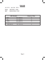
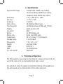
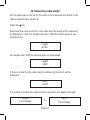
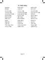
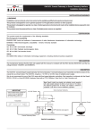
TRIPLETT
TDR
Cable Fault Finder
Instruction
Manual
Safety Warnings
This Instrument meets the safety requirements of IEC 61010-1:1993. It is
for use on de-energised circuits only, however the Instrument is protected
against telephone network voltages (EN60950: 1999 Scn2.3). Connection to
mains supply voltages will result in damage to the Instrument and/or a hazard to the operator. Hence the user must assume responsibility for ensuring
his or her own safety.
WARNING
ONLY use the unit with non-energized or deenergized and
suitably isolated circuits. Connection to AC power mains will
damage the instrument and may cause user injury.
Symbols used on Instrument
! Caution: Refer to accompanying notes.
CE Equipment complies with current EU directives
Page 1
Standards
UL 1311-1 and CUL 1311-1
Safety: IEC610101-1:1993
EMC
BS/EN 61326-1:1997
EMC Standard
ESD
IEC 1000-4-2
EM
IEC 1000-4-3
Burst
IEC 1000-4-4
Surge
IEC 1000-4-5
Conducted RF
1EC 1000-4-6
Page 2
Category of Pass
A
A
A
A
A
Table of Contents
1. First Operation
2. The TDR Cable Fault Finder
3. Specifications
4. Principles of operation
5. Attaching a cable to the Fault Finder
6. Setting the cable type
7. Selecting a library cable type
8. Testing cables not included in library
9. How to determine unknown Vp settings
10. Measuring cable length
11. Checking networks (thin wire ethernet)
12. Accuracy
13. Theoretical and actual Vp
14. Battery
15. Trouble Shooting
16. Cable Library
17. Additional Features
18. Maintenance and Warranty
Part # 84-891
Page 3
1. First Operation
The TDR Cable Fault Finder comes complete with
• Alligator Clip adaptor
• Alkaline 9v PP3 cell
• Toolbelt Holster Carry Case
IT IS IMPORTANT THAT YOU READ THIS
HANDBOOK BEFORE OPERATING THE
INSTRUMENT
Remove all packaging, remove battery compartment cover and check that
the battery is connected (see section 14).
Page 4
2. The TDR Cable Fault Finder
The Triplett TDR is a hand held battery powered unit designed to measure
the length of copper power and communication cables, or indicate the
distance to a fault on the cable, given access to one end only.
Advanced signal processing techniques enable the TDR to identify opens
and short circuits, and directly indicate the fault distance on an alpha-numeric display.
An internal library of standard cable types enables accurate measurement
without the necessity of entering Velocity of Propogation or Characteristic
Impedance information.
The TDR also incorporates an oscillating tone generator, that is detectable with a Triplett Hound, Hound 2, or Hound 3, for use in the tracing and
identification of cable pairs.
The TDR can be used to:
Measure the length of cable on a drum, without the need to unwind, and
given access to one end only.
Measure segment lengths in a Local Area Network, and distance to a fault.
Locate the distance to a fault on an installed cable run.
Page 5
3. Specifications
Approximate Range
Resolution
Accuracy
Vp Range
Cable Library
Tone Generator
Display Connector
Battery
Battery Life
Temperature
Storage Temp.
Dimensions
Weight
Safety
EMC
UL, CUL and CE Coaxial Cable: 6400ft max (1999m)
Structured Wiring: 2500ft max (750m)
Telephone Cable: 2500ft max (750m)
0.1ft < 100ft & 1ft > 100ft
+/- 3% or 1.5ft
0 to 99%
39 Standard Cable Types
Oscillating between 810Hz and 1110Hz
Alpha-numeric LCD
BNC
9v PP3 Alkaline cell
Better than 2000 tests
32 to 112 deg F (0 to 40 deg C)
0 to 150 deg F
7.9” x 3.1” x 1.4”
less than 0.55lb
IEC1010-1
To EU directives
Approved
4. Principles of Operation
The TDR works by measuring the time taken for a signal to travel to the far
end of the cable (or to an intermediate fault) and to return.
The velocity at which the signal is transmitted (Velocity of Propagation ie.
Vp) will depend on the characteristics of the cable under test.
Page 6
5. Attaching a cable to the TDR
1. Ensure that no power supply or equipment is attached to the cable to
be tested
2. Check that the far end of the cable is either open or shorted (not fitted
with a termination)
3. Attach the TDR to one end of the cable to be tested
The cable attachment to the TDR is via a BNC Jack located at the top of the
unit. For un-terminated cables use the alligator clip adaptor.
Coaxial Cable
Connect the red clip to the center wire and the black
clip to the shield.
Shielded Cable
Connect the red clip to a wire adjacent to the shield of
the cable and the black clip to the shield.
Unshielded
Twisted Pair Separate out one pair and connect the two clips
to the two wires of a pair.
Unshielded
Multi-Conductor
Cable
Connect the clips to any two wires.
Page 7
6. Setting the cable type
Before the TDR can be used to take measurements, it needs to be set for the
cable type to be measured.
If the cable is listed in the library (see Section 16) then setting up is simply
a matter of selecting the appropriate cable type.
7. Selecting a library cable type
1. Switch on the TDR with the ON/Off switch at the side of the unit
2. The display will show the previously selected cable setting with its Vp.
For example
E/net 9907
Vp=78%
3. Scroll through the library using the and keys to find the required
cable type. The types are displayed in alphabetical order and listed in
Section 16 of this user guide.
When the TDR is switched off it automatically stores the last setting and will
display this setting when powered up.
Page 8
8. Testing cables not included in library
If the cable type to be tested is not in the library, then it can still be tested if
the Vp is known. If the Vp is unknown refer to Section 9.
Using the Key scroll to the bottom of the library and beyond, until you
find the the Vp settings from 99% downwards.
9. How to determine unknown Vp settings
If the TDR is to be used with a cable type for which the Vp is unknown, this
first must be determined.
1. Take a sample of the cable at least 60 feet in length
2. Measure its length by direct measurement
3. Connect to the TDR and adjust the Vp setting to give a reading of the
correct length .
This Vp setting can now be noted and used on unknown lengths of the
same cable type.
Page 9
10. Measuring cable length
Set the cable type or the Vp for the cable to be measured and attach to the
cable as described in section 5.
Press the
Key
Assuming there are no shorts in the cable then the length of the cable will
be displayed, in feet. For lengths less than 100ft this will be given to one
decimal place.
Length
63.9ft
For lengths over 100ft the decimal place is suppressed.
Length
345ft
If there is a short in the cable then the distance to the short will be
displayed.
Short
40.2ft
If the cable is outside the measurement range then the display will read:
Length
Out of Range
or
Page 10
Short
Out of Range
11. Checking networks (thin wire ethernet)
While carrying out the following tests, equipment should NOT be connected
to the network.
Set TDR with network cable type ie. E/net 9907, remove 50Ω terminators
from both ends of network.
Connect TDR in place of one of the terminators.
Press
Length of network will be displayed as:
Length
XX.Xft
Repeat measurement from other end of network
The length shown should be the same from either end and indicate the total
length of the network. If the lengths differ and are less than the expected,
this is probably due to an open circuit in the network at the distance shown
If displays of:
Short
XX.Xft
are shown this indicates a short circuit in the network at the distance shown
Disconnect TDR and refit terminators.
Page 11
12. Accuracy
For coaxial twisted pair and shielded types an accuracy of ±5% can be
expected, or ± 1.5ft at less than 30ft.
The velocity of propagation is less well defined with unshielded multiconductor cable, including AC mains cable, and is lower when the cable is
tightly wound on a drum than when it is installed.
This is due to capacitance and inductance effects between the turns, therefore limiting accuracy to ±10% or ± 3ft at less than 30ft.
The BNC to alligator clip adaptor has an effective length of 4 inches.
13. Theoretical and actual Vp
Vp can, in theory be calculated from the dielectric constant, but actual
values often differ slightly from the theoretical. In a real cable the dielectric
may not fill the space between the conductors completely, and this has the
effect of increasing Vp.
In twisted pair cables the Vp depends to an extent on the pitch of the twist.
The tighter the pitch the more dielectric and less air space and so the Vp is
higher.
This has an implication for Cat 5, where the different pairs are deliberately
given staggered pitches to reduce crosstalk. Variation of Vp between pairs
with Cat 5 is typically ±2%.
Page 12
14. Battery
The TDR requires a standard 9 volt alkaline battery.
When the battery has become discharged, and needs replacing, the display
shows:
Low
Battery
To replace battery, switch off the TDR, remove battery cover and replace
battery. Replace the cover.
15. Trouble Shooting
If display shows:
Length
Out of Range
Check length of cable under test is within specified range of TDR
Check connections from TDR to cable under test. Check for open circuit in
cable at less than 5 feet. Check alligator clip to BNC adaptor lead. Connect
alligator clips together, press
If display reads:
Short
Out of Range
Then the adaptor lead is OK.
Page 13
If display reads:
Length
Out of Range
Then the adaptor lead needs replacing or repairing.
If display shows:
Short
Out of Range
Check cable under test for short circuit at less than 7.5ft. Check that terminators have been removed from network. Length to short circuit is outside
of range, check by reconnecting to opposite end of cable if possible.
If the display shows:
Low
Battery
Replace battery.
If the display is blank:
Check if good battery is installed in TDR. Install or replace battery
If cable length measurement appears to be inaccurate:
Check that cable type or Vp value have been correctly selected Conductors
within cable may be broken, select alternative conductors if available.
Page 14
16. Cable Library
Appletalk
BT2002
Coax Air 50Ω
Coax A/S 75Ω
Coax Solid PE 50Ω
Ethernet 9880
Ethernet 9907
IBM Type 9
RG6/U
RG59 B/U
T/Pair PE
T/Pair Paper 72nF
Twinax 100Ω
Belden 8102
CAT5 STP
Coax Air 75Ω
Coax Foam PE 50Ω
Coax Solid PE 75Ω
Ethernet 9901
IBM 1/2A/6
Mains BS6500
RG58 (8219)
RG62 A/U
T/Pair PTFE
T/Pair Paper 83nF
URM70 Coax
Page 15
Belden 9933
CAT 5 UTP
Coax A/S 50Ω
Coax Foam PE 75Ω
CW1308
Ethernet 9903
IBM Type 3
Multicore PVC
RG58 C/U
Jelly PE
T/Pair PVC
Twinax 78Ω
URM76 Coax
17. Additional Features
Units of measurement
Choice of Units. The Cable Fault Finder will display cable lengths either in
meters or feet.
To change the units to be used, switch the TDR off, then switch on while
holding down the key. The unit in use, either “Meters” or “Feet” will be
displayed.
Toggle from one to the other using the
switch off, then on again.
key. To resume normal operation
Tone Generator
In Warble Mode the TDR generates a warbling tone, which is transmitted
down the cable under test and can be picked up with a standard tone probe
like the Triplett Hound 2 or Hound 3 (optional). This facilitates cable tracing.
To select Warble Mode, switch the TDR off, then switch on again while
holding down the key. The message “Warble” will appear on the display.
To resume normal operation switch off, then on.
Page 16
18. Maintenance and Warranty
No regular maintenance of the Triplett TDR is required. In the event
the product is defective or is damaged, please contact Triplett for repair
information.
Triplett Product Return Instructions
In the unlikely event that you must return your Triplett equipment for repair, the
following steps must be taken.
1: Call 1-800-TRIPLETT to obtain a Return Material Authorization (RMA) number
from Customer Service.
2: Enclose a copy of the original sales receipt showing date of purchase.
3: Clearly print the RMA number on the outside of the shipping container.
4: Return to: Triplett / Jewell Instruments
850 Perimeter Road
Manchester, NH 03103
ATTN: Repair Dept.
Page 17
Triplett Three Year Limited Warranty
Triplett warrants instruments and test equipment manufactured by it to be
free from defective material or workmanship and agrees to repair or replace
such products which, under normal use and service, disclose the defect to
be the fault of our manufacturing, with no charge within three years of the
date of original purchase for parts and labor.
If we are unable to repair or replace the product, we will make a
refund of the purchase price. Consult the Instruction Manual for instructions regarding the proper use and servicing of instruments
and test equipment. Our obligation under this warranty is limited
to repairing, replacing, or making refund on any instrument or test equipment which proves to be defective within three years from the date of
original purchase.
This warranty does not apply to any of our products which have been
repaired or altered by unauthorized persons in any way so as, in our sole
judgment, to injure their stability or reliability, or which have been subject to
misuse, abuse, misapplication, negligence, accident or which have had the
serial numbers altered, defaced, or removed.
Accessories, including batteries and fuses, not of our manufacture used
with this product are not covered by this warranty.
To register a claim under the provisions of this warranty, contact Triplett’s
Customer Service Department for a Return Authorization Number (RMA)
and return instructions. No returned product will be accepted without an
RMA number. Upon our inspection of the product, we will advise you as to
the disposition of your claim.
Page 18
Triplett Three Year Limited Warranty
ALL WARRANTIES IMPLIED BY LAW ARE HEREBY LIMITED TO A PERIOD
OF THREE YEARS FROM DATE OF PURCHASE, AND THE PROVISIONS OF
THE WARRANTY ARE EXPRESSLY IN LIEU OF ANY OTHER WARRANTIES
EXPRESSED OR IMPLIED.
The purchaser agrees to assume all liability for any damages and bodily
injury which may result from the use or misuse of the product by the
purchaser, his employees, or others, and the remedies provided for in this
warranty are expressly in lieu of any other liability Triplett may have, including incidental or consequential damages.
Some states (USA ONLY) do not allow the exclusion or limitation of incidental or consequential damages, so the above limitation or exclusion may not
apply to you. No representative of Triplett / Jewell Instruments or any other
person is authorized to extend the liability of Triplett in connection with the
sale of its products beyond the terms hereof.
Triplett reserves the right to discontinue models at any time, or change
specifications, price or design, without notice and without incurring any
obligation.
This warranty gives you specific legal rights, and you may have other rights
which vary from state to state.
Page 19