1
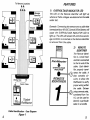
The PairWaster
LAN CABLE TEST SET
FROM TRIPLETT CORPORATION
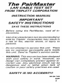
INSTRUCTION MANUAL
IMPORTANT
SAFETY INSTRUCTIONS
SAVE THESE INSTRUCTIONS
- Before using the PairMaster, read all in-
structions.
Use of an attachment not recommended or
sold by Triplett Corporation may result in
a risk of fire, electric shock, or injury to
persons.
- Do not attempt to service this unit. There
are no customer serviceable parts inside
this unit. Send to Triplett's service center.
WARNING: This test set has been designea
With your safety in mind. However, no
design can completely protect against in-
correct use. Any electrical circuit can be
dangerous and or lethal when lack of
caution or poor safety practices are used.
SAFETY IS NO ACCIDENT!!!
PN 84-740
8/94
7
PAIRMASTER ACCESSORIES
DESCRIPTION Cat. No.
Remote Identifier #1 3240-1
Remote Identifier #2 3240-2
Remote Identifier #3 3240-3
Remote Identifier #4 3240-4
Remote Identifier 45 3240-5
Remote Identifier #6 3240-6
Remote Identifier #7 3240-7
Remote Identifier #8 3240-8
Remote Identifier #9 3240-9
Remote Identifier 410 3240-10
Remote Identifier #11 3240-11
Remote Identifier #12 3240-12
Remote Identifier #173 3240-13
Remote Identifier #14 3240-14
Remote Identifier 415 3240-15
Remote Identifier #16 3240-16
Remote Identifiers #1 to #4 3240-17
Remote Identifiers #5 to #8 3240-18
Remote Identifiers 49 to 412 3240-19
Remote Identifiers #13 to #16 3240-20
Hard-Sided Carrying Case w/strap 10-3959
Soft Carrying Case 10-2961
RJ-45 Patch Cable (Category 5) 26-889
RJ In-Line Coupler 2455-781
TABLE OF CONTENTS
SECTION 1:
OVERVIEW... eee eee 3
TE EL 5
SECTION 2:
OPERATING INSTRUCTIONS. ............................ &
FAULT CODES.........o oes 70
DISPLAY FACES. .......uuureeeooororeaaczeeoeoeecooo 11
SECTION 3:
SPECIAL CABLE TESTING... 73
SECTION 4:
SPECIFICATIONS... eee, 14
WARRANTY.........sscccccrrrrr rar ar nr ren n annees 16
2
PAIRMASTER OVERVIEW
The PairMaster gives the user the ability to verify
three basic requirements for LAN cabling. First,
the PairMaster will check the point to point wiring.
These tests, commonly called wire-mapping, tell
the user whether or not the individual conductors
within the cable are wired correctly at both ends.
Another test, NEXT (Near End Crosstalk), checks
each pair of the cable for excessive A.C. coupling
to the other pairs. The third major feature is the
ability to identify which cable in the bundle is
connected to the PairMaster. In a typical LAN
installation, the individual workstations are con-
nected to a central wiring hub. By connecting the
sixteen Remote Identifiers to the workstation ends
of the cables, the user can easily document the
network topology from one location (see Fig. 1).
To Remote Locations
AA
A
Remote
Identifier
| Wiring Hub 3j
{ Pa ich Cable
Fault Codes |
| | m :
веет Triplett
CORPORATION
PairMaster |
Cable Identification - User Diagram
Figure 7
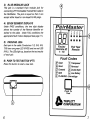
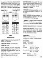
FEATURES
1) OVERVOLTAGE INDICATOR LED
The LED on the Remote Identifier will light up
whenever Telco voltages are detected on the cable
under test.
Example: Connecting the remote onto a cable that
Is energized by a 48 VDC Central Office Battery will
cause the OVERVOLTAGE INDICATOR LED to
light up. The LED will remain ON until the overvolt-
age condition is corrected or the Remote Identifier
Is removed from the cable.
2) REMOTE
IDENTIFIER
The Remote Identi-
fier 1s a small mod-
ule thatis connected
E to the far end of the
OVERVOLTAGE cable. Each /denti-
INDICATOR fier properly termi-
a (7) nates the cable. It
also contains cir-
REMOTE cuitry to allow the
IDENTIFIER PairMaster to verify
proper wiring within
the cable. Sixteen
unique remote units,
numbered from 1 to
16, can be used to
identify a particular
cable in a bundle.
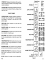
3) RJ-45 MODULAR JACK
This jack is a standard 8-pin modular jack for
connecting UTP (Unshielded Twisted Pair) cable to
the PairMaster. The jack is keyed so that it can
accept either keyed or non-keyed RJ-45 plugs.
4) SEVEN SEGMENT DISPLAYS
Under PASS conditions, the two digit display
shows the number of the Remote Identifier at-
tached to the cable. Under FAIL conditions the
appropriate Fault Code is displayed (see page 11).
5) PASS/FAIL LEDs
Each pair in the cable (Conductors 1/2, 3/6, 4/5,
7/8) have one green LED (PASS) and one red LED
(FAIL). The LEDs light up, based on the test results
of each pair.
6) PUSH-TO-TEST BUTTON (PTT)
Press this button to start a new test.
-
©
PehirMaster
3 4 7
6
2 8 5 6
0 00
Faults/ Pair Test
Remote ID Results
17-16
Fault Codes
Open
Short
Transposed
Reversed
Crossed Double Split
Split
Low Battery
FLASHING - Overvoltage
¿a
ur
Push To
Test
TRIPLETT
CORPORATION
OPERATING INSTRUCTIONS
Connect each Remote Identifier into the terminal
jack of an office. Observe the OVERVOLTAGE
INDICATOR LED on the remote. If the LED is on,
Telco voltage is present. Remove the Remote
Identifier and investigate the problem. The Pair-
Master is not intended for use on public telephone
systems.
*** WARNING *** Never connect any LAN
device to an overvoltage line. Damage to the hub
or to the terminal may result.
Connect the RJ-45 patch cable to the wiring hubs
patch panel. Plug the other end of the patch cable
into the PairMaster's RJ-45 jack.
** NOTE ** Using the patch cable and the in-line
couplers is recommended to reduce wear on the
PairMaster's RJ-45 jack.
Press the PUSH-TO-TEST (PTT) button to begin
testing the cable for proper wiring. Observe the
seven segment display. Upon pressing the PTT
button, one of three displays will be shown. Under
normal conditions the segments will read "--" for
about one second. This shows the user that the
PairMaster is beginning to test the cable. When the
battery voltage is low the segments will read "Lb".
instead of "--". The PairMaster is still beginning
to test the cable, but erroneous readings may
occur. Whenever "Lb" appears, the user should
replace the 9 volt battery. The third display occurs
when the PairMaster is connected to a Telco
energized cable. The display will flash "OL" until
the overvoltage is removed. After removing the
8
PairMaster from the energized line, the user must
wait for about 15 seconds before pressing the PTT
button. The internal power supply in the PairMas-
ter will not be able to reactivate until its time-out
period has expired (about 15 seconds).
** NOTE ** In the event that the PairMaster and
the Remote Identifier are both connected to a Telco
energized cable, only the PairMaster will give an
overvoltage (OL) indication. The OVERVOLTAGE
INDICATOR LED will not light under these condi-
tions. In most situations, the Remote Identifier will
be connected to the line first. If a problem exists,
the user can tellif the line is energized immediately.
At the wiring hub (in another office) the user can
determine an overvoltage condition by using the
PairMaster itself.
Following the initial message at power-up, the
PairMaster tests each pair of the cable sequen-
tially. The pairs consist of the following conduc-
tors: 1/2, 3/6, 4/5, 7/8. The PASS/FAIL results of
each pair are displayed immediately following that
pair's tests.
If the pair has passed all tests, the green LED below
the pair number will light. The seven segment
LEDs will display the number of the Remote
Identifier connected to the other end of the cable.
If the pair fails one or more of the tests, the red LED
below the pair number will light. The seven seg-
ment LEDs will display the FAULT CODE associ-
ated with the failure. In the event of a multiple
failure on a single pair, the highest priority fault will
be displayed. The fault codes are listed in order of
priority on page 10.
9
POWER-UP: Displayed immediately after push-to-
test (PIT) button is pressed, if everything is under
normal conditions.
LOWBATTERY: Displayed immediately after push-
to-test button is pressed If battery voltage is less
than 6.5 volts.
FAULT CODES
OVERVOLTAGE: Damaging voltage is present on
the cable. The unit will flash "OL" until the damag-
Ing voltage is removed or until time out of the
power supply.
OPEN PAIR: Either conductor of a pair does not
have continuity.
SHORTED PAIR: Both conductors of a pair are
shorted together.
CROSSED PAIR: One conductor of apairis shorted
to a conductor of another pair.
SPLIT PAIR: One conductor of a pair is connected
to the wrong destination at the other end of the
cable.
TRANSPOSED PAIR: Both conductors of a pair are
connected to the wrong destination at the other
end of the cable.
REVERSED PAIR: The conductors of an individual
pair are reversed in polaritry at one end of the cable.
DOUBLE SPLIT PAIR: The conductors of two pairs
have correct continuity but have excessive AC
crosstalk.
NO ID: (Flashes) The cable can not be identified.
70
DisplayFaces Wiring
POWER-UP | — — 9
A
Low an em | by Es
OVERVOLTAGE OL
a a
10-9 0-91
OPEN PAIR [IF 2 Gnd) 2
1 aie 2
SHORTED PAIR > 4
1 9-0 |
2 2
CROSSED PAIR q Ea 5
1 Den |
2 2
SPLIT PAIR я CA
5 O-—— — ——0 6
1 1
Ir |>eX—e:
TRANSPOSED PAIR | : 3
PRD:
REVERSED PAIR | ГО 2 >
o -—
2 2
wo no] 1d
(FLASHES)
Figure 2
—
—
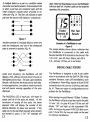
A multiple failure on a pair is a condition where
more than one fault is present. One example of this
IS when a pair has one conductor open and the
other conductor crossed (short circuited) to an-
other pair (Fig. 3). The first will indicate an open
pair and the second will indicate a crossed pair.
e —€e:
20 2
:0
6 @-
3
@ s
Figure 3
Another example of a multiple failure is when two
pairs are transposed, and one of the transposed
pairs is reversed in polarity (Fig. 4).
Figure 4
Under both situations, the PairMaster will still
display a FAIL LED but will only inform the user of
the highest priority fault. The user, upon checking
the pair, will discover the lower priority fault also.
In most applications, the cable is wired incorrectly
and will require rewiring regardless of the error
displayed.
The PASS/FAIL LED of each pair, will retain its
status until all of the pairs are tested. At the
conclusion of testing all four pairs, the seven
segment LEDs will display the number of the
Remote Identifier for about two seconds. If the
cable can not be identified (typically when all pairs
are shorted or open), a “no” “id” message will
12
flash. When the final display is over, the PairMaster
will shut itself off. Another cable can be tested by
repeating this procedure.
1 3
2 6
OR
O CO O
4 7
5 8
~@® O
Faults/
Remote ID
71-176
Pair Test
Results
Example of a PairMaster in use.
Figure 5
The sample display shown above, indicates that
the PairMaster is connected to the cable with
Remote Identifier #15 attached to the farend. Pair
1/2 1s O.K., pair 3/6 has a failure, pair 4/5 is
O.K., and pair 7/8 has yet to be tested.
SPECIAL CABLE TESTING
The PairMaster is designed to test 4 pair cables
wired in accordance with the EIA/TIA 568 wiring
standard. However, many LAN installations, such
as Ethernet or Token-Ring, require an 8 pin RJ-45
connection but only use two of the four pairs (see
fig. 6). These two types of configurations are no
problem for the PairMaster.
When testing two pair Ethernet (10 Base-T) cables,
the PairMaster will give actual test results for pairs
1/2 and 3/6. On pairs 4/5 and 7/8 the unit will
display "OP" and light up the associated FAIL
LEDs. As long as the green PASS LEDs light up on
pairs 1/2 and 3/6, the two pair cable can be used
for Ethernet installations. 13
Testing two pair Token-Ring cables is similar to
testing the Ethernet cables. The difference is that
instead of pairs 1/2 and 3/6, the usable readings
occur on pairs 3/6 and 4/5. Pairs 1/2 and 7/8 will
display (OP), as described on the previous page.
Ethernet (802.3) Token-Ring (802.5)
17
PAR nme Г
12345678
12345678
]
TT |
Pair | Contact oido
Pair | Contact | Function
1/2 Not
== Tip 36| 3 |
4/5| 4 |Not 4/5 Ring
5 |Used 5 | Tip
7/8| 7 | Not 7/8| 7 | Not
8 Used 8 Used |
Figure 6
SPECIFICATIONS
CABLE TYPES: EIA/TIA 568 configuration forUTP
Ethernet and Token Ring.
CABLE PAIRS TESTED: 1/2, 3/6, 4/5, 7/8
CONNECTOR: RJ-45
FAULTS DETECTED: Open pairs, Shorted pairs,
Crossed pairs, Split Pairs, Transposed Pairs, Re-
versed pairs, and Double Split pairs - NEXT less
than 21 dB +/- 4 dB
DISPLAY LEDs: Two seven segment displays, Four
PASS LEDs (Green), Four FAIL LEDs (Red)
14
INPUT PROTECTION: Withstands 56 VDC limited
by 400 ohms series resistance. Withstands 175 V
peak 20 - 60 Hz with 100 ohms series impedance
superimposed onto 56 VDC for 100 mS.
(Standard TELCO signals).
PAIRMASTER (with input protection): Overvolt-
age conditions are reported by a flashing "OL" on
the display.
REMOTE IDENTIFIER (with input protection): Ov-
ervoltage conditions are reported by the OVER-
VOLTAGE INDICATOR LED lighting up.
* WARNING * Connecting either the PairMaster
or the Remote Identifiers to a live power system
(170 VAC 60 Hz) will result in permanent damage.
MAXIMUM CABLE LENGTH: 400ft. (122 meters)
ANOMALIES IN IMPEDANCE: Improper charac-
teristic impedances may result in false readings
(Incorrect ID indication). Excessive cable lengths
may also cause erroneous readings.
POWER SUPPLY:
PairMaster: 9 Volt Alkaline Battery
Remote Identifier: Passive - no battery required.
ENVIRONMENT:
Storage: -20°C to 60°C
Operating: O°C to 50°C
S/ZE: L x W x H
PairMaster: 6.0 x 3.3 x 1.3 inches
(152 x 84 x 33 mm)
Remote Identifier: 2.6 x 1.4 x 0.6 inches
(66 x 35x 14 MM)
WEIGHT: PairMaster 9.2 oz.
Remote Identifier 1.2 oz.
75
LIMITED WARRANTY
The Triplett Corporation warrants instruments and test
equipment manufactured by it to be free from defective
material or workmanship and agrees to repair or replace such
products which, under normal use and service, disclose the
defect to be the fault of our manufacturing, with no charge
within two years (PairMaster) - one year (Remotes) of the
date of original purchase for parts and labor. If we are unable
to repair or replace the product, we will make a refund of the
purchase price. Consult the Instruction Manual for instruc-
tions regarding the proper use and servicing of instruments
and test equipment. Our obligation under this warranty 1$
limited to repairing, replacing, or making refund on any
instrument or test equipment which proves to be defective
within two years (PairMaster) - one year (Remotes) from the
date of original purchase.
This warranty does not apply to any of our products which
have been repaired or altered by unauthorized persons in any
way so as, in our sole judgment, to injure their stability or
reliability, or which have been subject to misuse, abuse,
misapplication, negligence, accident or which have had the
serial numbers altered, defaced, or removed. Accessories,
including batteries and fuses not of our manufacture used
with this product are not covered by this warranty.
To register a claim under the provisions of this warranty,
return the instrument or test equipment to Triplett Corpora-
tion, Bluffton, Ohio 45817, transportation prepaid. Upon
our inspection of the product, we will advise you as to the
disposition of your claim.
ALL WARRANTIES IMPLIED BY LAW ARE HEREBY LIMITED
TO A PERIOD OF TWO YEARS (PAIRMASTER) - ONE YEAR
(REMOTES) AND THE PROVISIONS OF THE WARRANTY
ARE EXPRESSLY IN LIEU OF ANY OTHER WARRANTIES
EXPRESSED OR IMPLIED.
The purchaser agrees to assume all liability for any damages
and bodily injury which may result from the use or misuse
of the product by the purchaser, his employees, or others,
and the remedies provided for in this warranty are expressly
in lieu of any other liability Triplett Corporation may have,
including incidental or consequential damages.
Some states (USA ONLY) do not allow the exclusion or
limitation of incidental or consequential damages, so the
above limitation or exclusion may not apply to you. No
representative of Triplett Corporation or any other person is
authorized to extend the liability of Triplett Corporation in
connection with the sale of its products beyond the terms
hereof.
Triplett Corporation reserves the right to discontinue models
at any time, or change specifications, price or design,
without notice and without incurring any obligation.
This warranty pes you specific legal rights, and you may
have other rights which vary from state to state.
TRIPLETT CORPORATION, BLUFFTON, OHIO
16