1
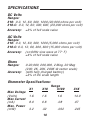
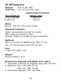
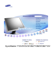
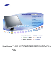
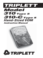
TRIPLETT
Model
310 Type 8
310-C Type 8
Hand-Sized VOM
Instruction Manual
1
TABLE OF CONTENTS
SAFETY RULES ............................................... 3
INTRODUCTION .............................................. 9
SPECIFICATIONS ........................................... 10
GENERAL INSTRUCTIONS ................................ 12
Test Leads ............................................. 12
Range Selection ...................................... 12
Scale Selection ....................................... 13
Polarity Selection (310-C only) .................... 13
Changing Settings .................................... 13
Zero Adjustment ...................................... 13
Other Considerations ................................ 14
Care .................................................... 14
CONTROL LOCATION DIAGRAM ......................... 15
DC VOLTAGE MEASUREMENTS .......................... 16
AC VOLTAGE MEASUREMENTS .......................... 18
RESISTANCE MEASUREMENTS .......................... 20
DC CURRENT MEASUREMENTS ......................... 22
MEASURING OUTPUT VOLTS (dB) ...................... 24
OPERATION CHART ........................................ 26
ACCESSORIES .............................................. 27
MAINTENANCE ............................................. 28
TRIPLETT LIMITED WARRANTY ....................... 30
84-870
11/06
2
SAFETY RULES • WARNING
This tester has been designed with your safety in mind.
However, no design can completely protect against incorrect use. Electrical circuits can be dangerous and/
or lethal when lack of caution or poor safety practices
are used.
WARNING
This meter is NOT to be used to measure High Energy
circuits (power circuitry fused at greater than 4KW, such
as distribution circuits, power entrance circuits, etc.) or
circuits classified by CE as CATEGORY III (CAT III).
SAFETY RULES AND WARNINGS
• Read all instructions in this manual before using this meter.
• Prior to using this meter in any situation which could result
in injury to the user, in order to verify that the meter is
functional and producing a valid reading, test the meter on
a circuit(s) known to have potentials equivalent to the
potential that is to be measured. For example, before using
the meter to determine if an AC power line is energized with
120VAC, test the meter on a line known to be energized
with 120VAC.
• Do not exceed the maximum voltage limitations of this
meter (see product specifications). Doing so may damage
the meter and/or injure the user.
• When using this meter in schools and workshops,
responsible teachers or skilled personnel must control the
usage of this meter.
• Follow the recommendations of any Trade Organizations or
Regulatory Agencies whose scope encompasses the use
of this meter.
3
• Do not use this meter with its battery cover open, its rear
case open, or with parts removed.
• Do not open this meter for maintenance without first
disconnecting the test leads from all external circuitry.
• Repairs and maintenance must only be carried out by
qualified service personnel or qualified electricians /
technicians who know the dangers of, and the safety rules
applicable to this type of equipment.
• Use caution when measuring circuits containing capacitors.
Capacitors can store dangerous levels of electricity, even
when the circuitry which they are in has been disconnected
from its power source.
• Use caution when working with voltages above 25 volts AC
or 35 volts DC. Such voltages may cause a life threatening
electrical shock.
• This meter is not for use by children.
• Always set the meter to the appropriate range, mode or
polarity before connecting it to the circuitry to be tested.
• Never attempt to make voltage measurements with the
Function switch set to any of the OHMS or MA ranges.
Doing so may damage the meter and/or injure the user.
• Do not operate the Range switch or Polarity switch (310-C
only) with the test leads connected to the circuitry to be
tested. Doing so may damage the meter and/or injure the
user.
• Before using the meter, examine both the meter and the
test leads for damage. Do not use the meter if damage
(damaged insulation, exposed metal, cracked case, burnt
smell, etc.) is evident.
• Do not use this meter to make measurements in adverse
environments such as rain, snow, fog, or locations with
steam, explosive gases or dusts. Doing so may damage the
meter and/or injure the user.
4
• Make sure both test leads are fully inserted into their respective input jacks (Black lead into COM and Red lead into
V•O•M). A loose test lead may cause the user to misinterpret the dangers present (the meter may read Zero when
dangerous voltage is present) or the loose lead may
accidentally short to other circuitry or shock the user.
• Do not use the meter if either the meter or the test leads are
wet, either from exposure to the weather, or after cleaning
the case of the meter. Doing so may cause injury to the user.
• Avoid usage near strong magnetic fields (magnets,
loudspeakers, transformers, motors, coils, relays,
contactors, electromagnets, etc.). The meter may display
readings that are in error, causing the user to misinterpret
the hazards present. For example, the meter may indicate a
low voltage when high voltages are actually present.
• Avoid usage near strong electrostatic fields (high voltage
power lines, televisions, computer monitors, etc.). The
meter may display readings that are in error, causing the
user to misinterpret the hazards present. For example, the
meter may indicate a low voltage when high voltages are
actually present.
• Avoid usage near strong RF fields (radio or television transmitters, etc.). The meter may display readings that are in
error, causing the user to misinterpret the hazards present.
For example, the meter may indicate a low voltage when
high voltages are actually present.
• Do not touch the tips of the test leads when making a measurement. Do not touch live circuitry when making a
measurement.
• Do not apply more than 1200 volts DC/AC rms sine between
the test leads and the earth ground. Doing so may damage
the meter and/or injure the user.
• If there is any doubt about the condition of the meter (i.e.
safe vs unsafe), remove the meter from service and secure
it in a location that will prevent its unintentional use.
5
• Do not use the meter if it does not appear to work correctly
on all ranges and in all modes.
• Do not use the meter if it has undergone long-term storage
under unfavorable conditions.
• Do not use the meter if it may have been damaged in
transport.
• Do not attempt immediate use of the meter when bringing
if from a cold environment to a warm environment.
Condensation of water, inside and outside of the meter, may
produce dangerous measuring conditions. Allow the meter
to warm to room temperature before using.
• Do not use meter in condensing atmospheres. That is, do
not use meter in conditions where ambient temperature and
humidity could cause condensation of water inside of meter.
Doing so may cause injury to the user.
• Use caution when attempting to evaluate if a dangerous
voltage is present. The meter will not read AC voltage if it is
set to DC. For example, if the meter is set to 300VDC, it will
not measure a dangerous AC voltage, even if the probes are
inserted into a household AC wall outlet.
• Do not touch the metallic portion of one test lead if the
other test lead is connected to a live circuit. The current
from the live circuit may pass through the meter and appear
on the unconnected test lead. Failure to observe this
warning may result in user injury.
• Remove the battery when the meter may be left unused for
longer than 1 month. Chemical leakage from the battery
could damage the meter, leading to user injury.
• Do not use the meter if there is evidence of chemical
leakage from the battery. Leakage could damage meter and
lead to injury of user.
• Do not modify the meter. Changing the design may make
the meter unsafe and may result in injury to the user.
6
• Do not mistake a downscale reading as an indication that no
potential is present. Dangerous potentials may be present
that may result in user injury.
• When replacing the battery, dispose of the depleted battery
in accordance with any prevailing safety or environmental
regulations.
• A static charge on the face of the meter may cause the
meter to produce inaccurate readings, which could lead to
user injury. This condition is usually observed in dry
climates, when the face of the meter is rubbed with a cloth.
Apply Antistat solution, or mild detergent, to the face of the
meter to dissipate the static charge.
READ THE MANUAL
Read this Instruction Manual carefully and completely.
Voltages and currents within the capability of this test
equipment can be hazardous. Follow the instructions
in this manual for every measurement. Read and understand the general instructions before attempting
to use this tester. Do not exceed the limits of the tester.
SAFETY CHECK
Double check the switch setting and lead connections
before making measurements. Are you following all
of the instructions?
Disconnect the tester or turn off the power before
changing switch positions. Do not connect to circuits
with voltage present when switch is in any ohms or
current position.
When replacing fuses, use only specified type fuses
and insert in correct fuse holder.
7
DO NOT TOUCH
Do not touch exposed wiring, connections or other
“live” parts of an electrical circuit. If in doubt, check
the circuit first for voltage before touching it.
Turn off the power to a circuit before connecting test
probes to it. Be sure there is no voltage present before you touch the circuit. Do not use cracked or broken test leads.
HIGH VOLTAGE IS DANGEROUS
Always start with the power off. Be sure there is no
voltage present before making connections to the circuit.
Don’t touch the tester, its test leads, or any part of the
circuit while it is on.
Before disconnecting the tester, turn the circuit off and
wait for the meter to return to “zero.”
DISTRIBUTION CIRCUITS PACK A PUNCH
In high energy circuits such as distribution transformers and bus bars, dangerous arcs of explosive nature
can occur if the circuit is shorted. If the tester is connected across a high energy circuit when set to a low
resistance range, a current range, or any other low
impedance range, the circuit is virtually shorted.
Special equipment designed for use with these circuits
is available. Contact a qualified person for assistance
before attempting to make measurements on any high
energy circuit.
SAFETY IS NO ACCIDENT
8
INTRODUCTION
The Triplett Model 310 and 310-C are hand-sized VOMs
with all the versatility and performance of larger, more
expensive bench-size models. They offer diode overload protection against damage to the meter movements caused by accidental overloads. A fuse is used
to protect the RX1 range. The fuse and batteries can
be easily replaced by removing the back cover.
Small enough to be carried in your tool box, glove compartment, brief case, or shirt pocket, the Model 310
features 20,000 ohms per volts DC sensitivity and
5,000 ohms per volt AC. The 310-C features 20,000
ohms per volt DC and 15,000 ohms per volt AC sensitivity.
Additionally, the 310-C incorporates a convenient Polarity Reversing Switch which electrically reverses the
test lead connections easily correcting accidental
downscale readings.
Versatility and readability have not been sacrificed in
order to provide a portable VOM. Both models have
18 different ranges that can be easily read on only 3
clearly defined scale areas. A single selector switch
allows you to switch easily from range to range and
function to function.
9
SPECIFICATIONS
DC Volts
Ranges:
310: 0-3, 12, 60, 300, 1200 (20,000 ohms per volt)
310-C: 0-3, 12, 60, 300, 600, (20,000 ohms per volt)
Accuracy:
±3% of full scale value
AC Volts
Ranges:
310: 0-3, 12, 60, 300, 1200 (5,000 ohms per volt)
310-C: 0-3, 12, 60, 300, 600 (15,000 ohms per volt)
Accuracy:
(on 60Hz sine wave at 77° F)
±4% of full scale value
Ohms
Ranges:
Accuracy:
0-20,000, 200,000, 2 Meg, 20 Meg
(200, 2K, 20K, 200K @ center scale)
(with fully charged battery)
±3% of DC scale length
Ohmmeter Specifications:
X1
Max Voltage
(Volts)
1.6
Max Current
(mA)
8.0
Max. Power
(mW)
3.2
X10
Range
X100
X1K
1.6
1.6
14.0
0.8
.08
.07
.32
.032
.245
10
DC Milliamperes
Ranges:
Accuracy:
0-.6, 6, 60, 600
±3% of full scale value
Current Range
0-.6, 6, 60 mA
0-600 mA
Approximate Full Scale
Voltage Drop
250 mV
330 mV
Meter
50 µA - 250 mV (Pivot and Jewel)
Overload Protection
Meter movement protected by diodes.
RX1 range protected by fuse.
Voltage ranges protected by high impedance.
Batteries
One 1.5 volt N-cell (NEDA 910) (PN: 37-21)
One 12 volt Eveready A23 (PN: 37-60)
Fuse
1/16A (PN: 3207-112)
Weight
Approximately 14 oz.
Accessories Supplied with Model 310 / 310-C
1. Test leads w/Screw-on Alligator clips (PN: 79-153)
2. Batteries: One 1.5V (PN: 37-21)
One 12V (PN: 37-60)
3. Instruction Manual (PN: 84-870)
11
GENERAL INSTRUCTIONS
Control Locations
For a diagram of the Model 310 / 310-C, please refer
to page 15.
Test Leads
Check the test leads periodically. Leads that are worn,
have damaged insulation, damaged plugs, damaged
probes or loose parts should be replaced.
The following section should be read carefully. It contains instructions and precautions to be observed in
making measurements with the tester.
The alligator clips provided with the tester fit over the
end of the test probes. When measuring high voltage, these alligator clips allow measurement without
handling the test probes. ALWAYS SHUT OFF THE
POWER source before attempting to connect alligator
clips.
Range Selection
When the approximate value of the quantity being measured is not known, ALWAYS START ON THE HIGHEST RANGE. For greater accuracy, choose the range
which will allow readings to be taken in the upper (right
hand) portion of the scale. See Operation Chart on
page 26.
12
Scale Selection
Readings are taken on the scale having the appropriate significant figures (both 3 and 300 volts are read
on the 0-300 scale) by multiplying or dividing by a
factor of 10 or 100 as indicated by the range/scale
ratio (i.e., on the 3 volt range, divide the scale readings by 100). See Operation Chart on page 26.
Polarity Selection (Model 310-C only)
The Polarity Reversing Switch allows the user to electrically reverse the test lead connections. That is, when
the user mistakenly connects the test leads to a circuit and obtains a “downscale” reading, the Polarity
Reversing Switch may be operated to obtain an “upscale” reading.
Changing Settings
The test probes should be disconnected from the voltage source (or the source shut off) before the Range
Switch or Polarity Reversing Switch (310-C only) position is changed. This practice will result in an increased life and reliability for the tester, as well as establishing a good safety practice.
Zero Adjustment
The Meter Zero Adjust Screw is located near the center of the tester. It should be periodically adjusted so
the meter pointer is on zero with no input into the
tester.
13
Other Considerations
Readings on the sensitive voltage, current and resistance ranges may sometimes be different than calculated values. Thermo-electric or electro-chemical reactions can sometimes generate voltage (and current)
in a circuit due to elevated temperatures for soldering, contact of dissimilar metals, chemical fumes or
moisture. Also, the fingers should never touch the
metal parts of the test probes since body resistance
can cause erroneous readings - particularly on the high
ohmmeter ranges.
Care
Although this instrument is portable and rugged, it
should be treated with care. Do not drop it or handle
it roughly.
Avoid placing it on a bench where machine tools are
used or severe vibration is encountered.
When possible, keep it in a place of moderate temperature. Avoid subjecting it to extreme temperatures
and severe temperature changes.
If the tester has not been used for a long period of
time, rotate the switch in both directions several times
to wipe the switch contacts for good contact.
14
CONTROL LOCATION DIAGRAM
DIAL SCALE
POLARITY
REVERSING
SWITCH
INDICATOR
NEEDLE
O
∞
(310-C ONLY)
ZERO
ADJUSTMENT
SCREW
BLACK
TEST LEAD
INPUT
JACK
RED
TEST LEAD
INPUT
JACK
COM
V
300
AC
V
60
12
DC
300
OHMS
ADJUST
CONTROL
V-O-M
OHM
S
X
3 1 1 X
K
0
1
X
0
0 1
60
12
MA
X
6
.6
6
6
0
0
3
0
VARIOUS RANGE SETTINGS
15
RANGE
SELECTOR
SWITCH
DC VOLTAGE MEASUREMENTS
0-3 through 0-300 Volts:
1.
2.
3.
4.
5.
6.
Insert test leads in VOM and COM jacks.
Set Range Switch to appropriate DCV range.
Set Polarity Switch to desired polarity (310-C only)
Connect probes across circuit to be measured.
Energize circuit.
Read voltage on the black AC-DC scale.
0-1200 Volts: *
1.
2.
3.
4.
5.
6.
Insert test leads in COM and 1200 VDC* jacks.
Set Range Switch to 3 DCV position.
Set Polarity Switch to desired polarity (310-C only)
Connect probes across circuit to be measured.
Energize circuit.
Read voltage on the black AC-DC scale.
DO NOT TOUCH THE VOM while
it is connected to high voltage!
*Model 310-C is 0-600 Volts.
16
DC VOLTAGE MEASUREMENTS
POLARITY
REVERSING
SWITCH
(310-C ONLY)
O
∞
OHMS
ADJUST
CONTROL
COM
V-O-M
1200V
DC
DC
V
300
60
12
3
+
SAFETY FIRST!
17
AC VOLTAGE MEASUREMENTS
0-3 through 0-300 Volts:
1.
2.
3.
4.
5.
Insert test leads in VOM and COM jacks.
Set Range Switch to appropriate ACV range.
Connect probes across circuit to be measured.
Energize circuit.
Read voltage on black AC-DC scale.
0-1200 Volts: *
1.
2.
3.
4.
5.
Insert test leads in COM and 1200 VAC* jacks.
Set Range Switch to 3 ACV.
Connect probes across circuit to be measured.
Energize circuit.
Read voltage on the black AC-DC scale.
DO NOT TOUCH THE VOM while
it is connected to high voltage!
*Model 310-C is 0-600 Volts.
18
AC VOLTAGE MEASUREMENTS
POLARITY
REVERSING
SWITCH
(310-C ONLY)
O
∞
OHMS
ADJUST
CONTROL
V-O-M
COM
1200V
AC
V
1200V
DC
AC
300
60
12
3
Set Range
to
300 ACV
SAFETY FIRST!
19
RESISTANCE MEASUREMENTS
X1 through X1K Ohms:
1.
2.
3.
4.
Insert test leads into VOM and COM jacks.
Set Range Switch to appropriate OHMS range.
Short test probes together.
Adjust OHMS ADJUST CONTROL until meter reads
zero ohms.
5. Connect probes to component to be measured.
6. Read ohms on OHMS scale (multiply value read by
multiplier indicated by the switch).
A fuse protects the X1 range against accidental overloads. If the fuse should blow, all OHMS ranges will
not operate.
DO NOT TOUCH circuitry while
making measurements.
DISCONNECT or ISOLATE the device being tested from
other circuitry.
NOTE: 1K equals 1000.
NOTE: The Polarity Reversing Switch has no effect in
the Ohms Ranges.
20
RESISTANCE MEASUREMENTS
POLARITY
REVERSING
SWITCH
(310-C ONLY)
O
∞
OHMS
ADJUST
CONTROL
COM
V-O-M
1200V
DC
K
1200V
AC
1
OHM
S
X
1
0 X
0 1 X
0 1
X
SAFETY FIRST!
21
DC CURRENT MEASUREMENTS
0-.6 through 0-600 Milliamperes:
1.
2.
3.
4.
Insert test leads into VOM and COM jacks.
Set Range Switch to appropriate mA range.
Set Polarity Switch to desired polarity (310-C only)
Connect the probes in series with the circuit
(use alligator clips).
5. Turn circuit on.
6. Read current on black AC-DC scale.
The approximate voltage drop across the Model 310
is shown in the specifications. Generally, this drop
will not affect the circuit. But, in low voltage circuits,
it may be necessary to compensate for this drop.
DISCONNECT POWER before connecting
the Model 310 into the circuit.
22
DC CURRENT MEASUREMENTS
POLARITY
REVERSING
SWITCH
(310-C ONLY)
O
∞
OHMS
ADJUST
CONTROL
COM
V-O-M
1200V
DC
1200V
AC
MA
6
.6
6
6
0
0
0
+
–
LOAD
SAFETY FIRST!
23
MEASURING OUTPUT VOLTS (dB)
POLARITY
REVERSING
SWITCH
(310-C ONLY)
O
∞
OHMS
ADJUST
CONTROL
COM
V-O-M
1200V
AC
V
1200V
DC
AC
300
60
12
3
AUDIO
AMPLIFIER
600Ω
SAFETY FIRST!
To read Output Voltage use the same procedure as shown on
page 18 for AC Voltage and convert readings to dB using the
chart on page 25.
24
25
10 1 .1
20 2 .2
30 3 .3
40 4 .4
50 5 .5
60 6 .6
70 7 .7
80 8 .8
90 9 .9
–26
–6
+14
V
O
L
T
S
–24
–4
+16
–22
–2
+18
–20
0
+20
1.89
–18
+2
+22
1.73
–16
+4
+24
6M
W
60
0Ω
–14
+6
+26
–12
+8
+28
DB
50
0Ω
6M
W
–10
+10
+30
–8
+12
+32
60
0Ω
1M
W
100 10 1
–6
+14
+34
–4
+16
+36
–2
+18
+38
.775
0
+20
+40
+2
+22
+42
MEASURING OUTPUT VOLTS (dB)
26
0 - 20,000
0 - 200,000
0 - 2 Meg
0 - 20 Meg
0 - .6
0-6
0 - 60
0 - 600
Ohms
DC mA
MA .6
MA 6
MA 60
MA 600
X1
X10
X100
X1K
ACV
3
ACV 12
ACV 60
ACV 300
ACV
3
ACV
3
0-3
0 - 12
0 - 60
0 - 300
0 - 600 (310-C)
0 - 1200 (310)
AC Volts
Ω
Ω
Ω
Ω
DCV
3
DCV 12
DCV 60
DCV 300
DCV
3
DCV
3
Set Switch
To
0-3
0 - 12
0 - 60
0 - 300
0 - 600 (310-C)
0 - 1200 (310)
Range
DC Volts
To
Measure
VOM
VOM
VOM
VOM
VOM
VOM
VOM
VOM
VOM
VOM
VOM
VOM
600 V AC
1200 V AC
VOM
VOM
VOM
VOM
600 V DC
1200 V DC
Lead Connections*
Black Lead "COM"
Red Lead Listed Below
OPERATION CHART
.01 mA
.1 mA
1 mA
10 mA
.05 Volt
.20 Volt
1 Volt
5 Volt
10 Volt
20 Volt
.05 Volt
.20 Volt
1 Volt
5 Volt
10 Volt
20 Volt
Each Scale
Div. Equals
*310-C Polarity Switch at + position
60 ÷ 100
60 ÷ 10
60
60 x 10
0 - 20K
0 - 20K x 10
0 - 20K x 100
0 - 20K x 1000
3 AC
12
60
300
60 x 10
12 x 100
300 ÷ 100
12
60
300
60 x 10
12 x 100
Read On
Scale
ACCESSORIES
Carrying Cases:
Model 369:
Cat. No. 10-1258
Model 369-S:
Cat. No. 10-1791
Model 369-T:
Cat. No. 10-1608
Case w/ Belt Loop:
Cat. No. 10-1269
Model 369-V:
Cat. No. 10-2959
27
Test Leads:
79-153:
79-206:
79-695:
79-722:
42” Test leads w/Screw-on Alligator Clips
48” Test leads with Alligator Clips (no probes)
Test leads with Pin Cushion Clips
Test leads with Spike Clips
MAINTENANCE FOR
MODEL 310/310-C
Battery Replacement
If the pointer cannot be adjusted to full scale on the
X1, X10, or X100 OHMS ranges, replace the 1.5V battery. Replace the 12V battery if the X1K OHMS range
cannot be adjusted for full scale.
1.5V Battery - NEDA 910F or 910M (PN: 37-21)
12V Battery - A23 (PN: 37-60)
Fuse Replacement
If none of the OHMS ranges work, replace the fuse.
Use a 1/16 AMP, 5 mm x 20 mm fuse. (PN: 3207-112)
Cleaning Plastic Window
The plastic window has been treated at the factory to
dissipate static charges. If cleaning is necessary use
cotton dipped in a solution of common household
detergent and water. After cleaning, allow the solution to dry without rubbing; the resultant detergent
film will effectively dissipate static charges.
CAUTION:
Solvents and liquids used in radio and TV shop work
may craze or scar the plastic window if applied to it.
28
Calibration
With normal use, readjustment of this VOM should
not be necessary. An occasional check of the VOM
against a known reference voltage or another VOM is
good practice. If there is a question about the accuracy of the VOM, it should be returned to the factory
or an authorized service center for a calibration check.
TRIPLETT PRODUCT RETURN INSTRUCTIONS
In the unlikely event that you must return your
Triplett equipment for repair, the following
steps must be taken.
1) Call 1-800-TRIPLETT to obtain a Return Material
Authorization (RMA) number from Customer Service.
2) Enclose a copy of the original sales receipt
showing date of purchase.
3) Clearly print the RMA number on the outside of the
shipping container.
4) Return to:
Triplett Corporation
One Triplett Drive
Bluffton, OH 45817
ATTN: Repair Dept.
Be sure to include a full description of the problem, and a telephone number, street address, or email address, where you
can be contacted, and a return address where the meter can be
shipped to upon repair.
29
TRIPLETT LIMITED WARRANTY
The Triplett Corporation warrants instruments and test equipment manufactured by it to be
free from defective material or workmanship and agrees to repair or replace such products
which, under normal use and service, disclose the defect to be the fault of our manufacturing, with no charge within three years of the date of original purchase for parts and labor. If
we are unable to repair or replace the product, we will make a refund of the purchase price.
Consult the Instruction Manual for instructions regarding the proper use and servicing of
instruments and test equipment. Our obligation under this warranty is limited to repairing,
replacing, or making refund on any instrument or test equipment which proves to be defective within three years (one year on calibration) from the date of original purchase.
This warranty does not apply to any of our products which have been repaired or altered by
unauthorized persons in any way so as, in our sole judgment, to injure their stability or
reliability, or which have been subject to misuse, abuse, misapplication, negligence, accident or which have had the serial numbers altered, defaced, or removed. Accessories,
including batteries and fuses, not of our manufacture used with this product are not covered
by this warranty.
To register a claim under the provisions of this warranty, return the instrument or test equipment to Triplett Corporation, Bluffton, Ohio 45817, transportation prepaid. Upon our inspection of the product, we will advise you as to the disposition of your claim.
ALL WARRANTIES IMPLIED BY LAW ARE HEREBY LIMITED TO A PERIOD OF ONE YEAR
AND THE PROVISIONS OF THE WARRANTY ARE EXPRESSLY IN LIEU OF ANY OTHER
WARRANTIES EXPRESSED OR IMPLIED.
The purchaser agrees to assume all liability for any damages and bodily injury which may
result from the use or misuse of the product by the purchaser, his employees, or others, and
the remedies provided for in this warranty are expressly in lieu of any other liability Triplett
Corporation may have, including incidental or consequential damages.
Some states (USA ONLY) do not allow the exclusion or limitation of incidental or consequential damages, so the above limitation or exclusion may not apply to you. No representative of Triplett Corporation or any other person is authorized to extend the liability of Triplett Corporation in connection with the sale of its products beyond the terms hereof.
Triplett Corporation reserves the right to discontinue models at any time, or change specifications, price or design, without notice and without incurring any obligation.
This warranty gives you specific legal rights, and you may have other rights which vary from
state to state.
TRIPLETT CORPORATION
BLUFFTON, OHIO
1-800-874-7538
www.triplett.com
30
31
Triplett Corporation One Triplett Drive
800-TRIPLETT
FAX: 419-358-7956
© Triplett Corporation
Bluffton, OH 45817
www.triplett.com
All Rights Reserved