1
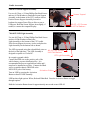
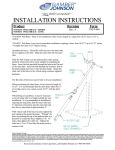
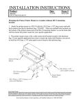
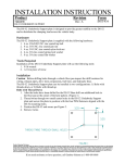
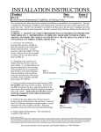
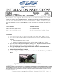
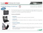
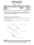
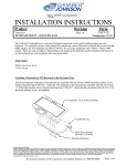
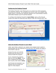
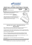
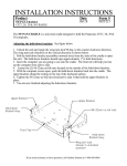
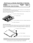
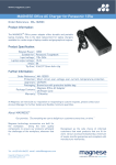
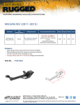
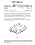
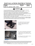
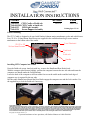
INSTALLATION INSTRUCTIONS
Product
7160-0415 CF53 Cradle w/PushLock
7160-0415-01 CF53 Cradle w/AutoLock
7160-0123
LED Light Asembly
7160-0124
Screen Support Assembly
Revision
Rev.A
Form
INST-564
Printing Spec: PS-001
Vehicle Mounting
The CF53 Cradle is designed to be used with Gamber-Johnson motion attachments, poles and vehicle bases.
Four .25-20 x .50 long Button Head Screws are supplied in the cradle hardware bag to secure motion
attachments to the bottom side of the cradle.
.25-20 x .50
Button Head Screws
Front Restraint
PushLock
or
AutoLock
Handle
Installing CF53 Computer into Cradle
Press the PushLock or turn AutoLock with key, to move the Handle and Rear Hooks back.
With the computer tilted forward slightly, position the computer between the two side tabs and insert the
computer case handle under the Front Restraint.
Lower the back of the computer so all four rubber feet are on the cradle surface and the back edge of
computer case is captured by the rear tabs.
Pull the cradle Handle forward until the Rear Hooks engage the computer case and the Lock catches. Use
the supplied key to lock the PushLock if necessary.
Product Mounting Disclaimer
Gamber-Johnson is not liable under any theory of contract or tort law for any loss, damage, personal injury, special, incidental or consequential damages for personal injury or other damage
of any nature arising directly or indirectly as a result of the improper installation or use of its products in vehicle or any other application. In order to safely install and use Gamber-Johnson
products full consideration of vehicle occupants, vehicle systems (i.e., the location of fuel lines, brakes lines, electrical, drive train or other systems), air-bags and other safety equipment is
required. Gamber-Johnson specifically disclaims any responsibility for the improper use or installation of its products not consistent with the original vehicle manufactures specifications
and recommendations, Gamber-Johnson product instruction sheets, or workmanship standards as endorsed through the Gamber-Johnson Certified Installer Program.
© copyright 2011 Gamber-Johnson, LLC
If you need assistance or have questions, call Gamber-Johnson at 1-800-456-6868
Cradle Accessories
7160-0124 Screen Support Assembly
Use two #8-32unc x .50 long Phillips Pan Head Screws
and two #8 Flat Washers to attach the Screen Support
Assembly to the bottom of the CF53 cradle as shown.
Position Screen Support Assembly forward or
backward to support Power Plug or allow access to
USB ports. Bend the Screen Support Arm slightly, if
needed, to contact the computer display.
Screen Support
#8-32 x .50 Screws
& #8 Flat Washers
7160-0123 LED Light Assembly
Use two #8-32unc x .50 long Phillips Pan Head Screws
and two #8 Flat Washers to attach the
Light Assembly to the bottom of the CF53 cradle.
If the Screen Support Accessory is also used place the
Light Assembly on the bottom side as shown.
The LED is powered using the red and black wires on
the back of the light base. The LED Assembly is
designed to operate on 12volts DC.
In a negative ground vehicle:
Connect the RED wire to the positive pole of the
vehicle battery or power distribution box. It is
recommended that a user-supplied fuse holder and 1
amp fuse be installed on red wire. Connect the Black
wire to a suitable chassis GROUND or the
NEGATIVE pole of the battery.
#8-32 x .50 Screws
& #8 Flat Washers
LED Light Assembly
Activation Button
Turn on LED by pressing the Activation
Button on head of LED Assembly.
LED has three light options: White, Red and White/Red. Press the Activation Button to toggle
throught options.
Hold the Activation Button down for approximately one second to turn LED off.