1
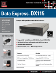
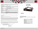
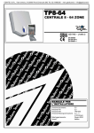
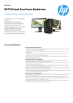
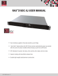
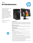
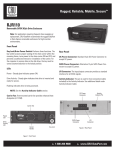
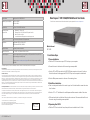
RTX220 QR - Manual
Data Express™ DX115 SAS/SATA 6G Quick Start Guide
Product Name
Data Express DX115 SAS/SATA 6G
Interface Types and Speeds
SATA: up to 6GB/s*
SAS: up to 6GB/s*
Compatibility
2.5-inch or 3.5-inch SATA hard drives
Operating System
Requirements
•
•
•
•
Torque
2.5” hard drives, M3 screws: 4 inch-pounds max.
Compliance
EMI Standard: FCC Part 15 Class B, CE
EMC Standard: EN55022, EN55024
Shipping Weight
3.8 pounts (includes accessories)
Product Dimensions
5.81” x 8.08” x 1.62” (148mm x 205mm - 41mm)
Technical Support
We don’t expect anything to go wrong with your CRU product. But if it does, Tech Support is standing by and ready to help.
For the full user manual and more information about this product, please visit www.cru-dataport.com
Windows 8, 7, Vista, or XP
Windows Server 2012, 2008, and 2003 product families
Mac OS X 10.4.x or higher
Linux distributions that support the connection type used
Models Covered:
DX115 6G
Contact us at www.cru-dataport.com/support. We also offer phone support at (800)
260-9800.
*For 6GB/s operation, a SAS or SATA 6GB/s controller and SAS or SATA 6GB/s hard drive are required.
Product Warranty
CRU-DataPort (CRU) warrants this product to be free of significant defects in material and workmanship for a period of five years from the original date of purchase.
CRU’s warranty is nontransferable and is limited to the original purchaser.
Limitation of Liability
The warranties set forth in this agreement replace all other warranties. CRU expressly disclaims all other warranties, including but not limited to, the implied warranties of merchantability and fitness for a particular purpose and non-infringement of third-party rights with respect to the documentation and hardware. No CRU
dealer, agent, or employee is authorized to make any modification, extension, or addition to this warranty. In no event will CRU or its suppliers be liable for any costs
of procurement of substitute products or services, lost profits, loss of information or data, computer malfunction, or any other special, indirect, consequential, or
incidental damages arising in any way out of the sale of, use of, or inability to use any CRU product or service, even if CRU has been advised of the possibility of such
damages. In no case shall CRU’s liability exceed the actual money paid for the products at issue. CRU reserves the right to make modifications and additions to this
product without notice or taking on additional liability.
FCC Compliance Statement: “This device complies with Part 15 of the FCC rules. Operation is subject to the following two conditions: (1) This device may not cause
harmful interference, and (2) this device must accept any interference received, including interference that may cause undesired operation.”
1. Installation Steps
1.1 Frame Installation
a. Slide the DX115 frame into an open 5.25” drive bay on your computer.
b. Secure the frame to the chassis with the mounting screws provided.
c. Attach a SAS or SATA data cable to the SAS/SATA data connector on the rear of the frame.
Attach the other end to the appropriate SAS or SATA port on the computer’s motherboard.
d. Attach a Molex power connector to the rear of the receiving frame.
1.2 Hard Drive Installation
a. Push in on the ejection handle of the carrier to pop it out. Use the handle to remove the carrier
from the frame.
This equipment has been tested and found to comply with the limits for a Class B digital device, pursuant to Part 15 of the FCC Rules. These limits are designed to
provide reasonable protection against harmful interference when the equipment is operated in a home or commercial environment. This equipment generates, uses,
and can radiate radio frequency energy and, if not installed and used in accordance with the instruction manual, may cause harmful interference to radio
communications.
b. Attach a 3.5” or 2.5” hard drive to the unified power and data connector inside of the carrier.
In the event that you experience Radio Frequency Interference, you should take the following steps to resolve the problem:
c. With one hand on the top of the hard drive, turn the carrier over. Then secure the hard drive to
the carrier using the mounting screws provided.
1) Ensure that the case of your attached drive is grounded.
2) Use a data cable with RFI reducing ferrites on each end.
3) Use a power supply with an RFI reducing ferrite approximately 5 inches from the DC plug.
4) Reorient or relocate the receiving antenna.
1.3 Operating Your DX115
FOR OFFICE OR COMMERCIAL USE
A7-115-0006-1 Rev. 2.0
a. Slide the DX115 carrier into the frame, then push the carrier handle in until it clicks.
RTX220 QR - Manual
b. Insert the included Data Express Key into the keylock and turning it 90 degrees clockwise to
secure the carrier to the frame.
c. Press and hold the Power Button to power the unit on until the Drive Ready LED begins to
flash and the hard drive inside begins to spin up.
2 Identifying the Parts of Your DX115 6G
Push Here to Eject Carrier
Drive Ready/Error
LED
Carrier Handle
Drive Activity LED
Fan Error LED
Disable Switch
Key Lock
NOTE: If the drive is already installed in the receiving frame before a system
power up, you do not have to press and hold the switch to power on the drive.
1.4 Safe Carrier Removal
b. Use the DataPort Key to turn the keylock 90 degrees counter-clockwise to unlock and power
off the unit.
c. Push the eject button below the keylock once to release the button, and again to eject the
carrier.
SAS/SATA
Connector
GND
a. Turn off the computer or properly dismount the drive from the system. Disconnecting the unit
without first unmounting the volume can result in data loss.
Windows Systems
Unmount the DX115 before powering it down by left-clicking the green arrow icon on the task
bar (in Windows XP) or the USB plug icon with the green checkmark on the Desktop task bar
(Windows Vista, 7, 8), and then selecting the proper device from the menu that pops up. You
may have to click on the “Show Hidden Icons” arrow on the task bar to find the correct icon.
Windows will indicate when it is safe to disconnect the DataPort 25.
Power Connector
Click-connect plate
When any hard drive is first used with the DataPort 25 Secure it will show up as a blank,
unallocated drive and you’ll need to format the drive inside the enclosure before you can use it.
Note that formatting a drive will erase all data on the drive, so be sure to back up your
data before beginning this operation.
Mac Systems
Unmount the volume before powering down the unit by dragging the
volume’s icon to the trash bin, or by selecting the volume then pressing
Command-E.
Power Switch
Figure 1: Front Bezel
Host Activity
LED Pin
Reserved
Pins
Cooling
Fan
HDD LED
Activity Disable
Figure 2 - DX115 Receiving Frame Rear Panel
3 Other Configuration Options
3.1 LED Activity
LED Name
Drive Ready/Error
Drive Activity
Color
Blue/Red
Amber
State
Description
Flashing Blue
Drive is inserted and powering up.
Solid Blue
Drive is powered on and ready for access.
Flashing Red and Blue
Fan failure. Please contact Technical Support.
Solid Red
DC power failure. Please contact Technical Support.
Flashing
Indicates when the host computer is accessing data on
the drive.*
*Some SATA PC systems/host controllers provide support for the Drive Activity LED feature (refer to the SATA PC
system/host controller manufacturer’s documentation for further information). The Drive Activity LED can be enabled
via host connection (cable not included) to Pin 1 located on Receiving Frame Motherboard (Figure 2). Refer to the SATA PC
system/host controller manufacturer’s documentation for further information.
3.2 Fan Error LED Disable Switch
This switch (see Figure 1) allows the user to disable the Fan Error LED (insert a paper clip or similar
object to activate switch). CRU-DataPort recommends replacing a faulty fan immediately. Contact
Technical Support to obtain a new fan.