1
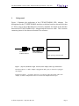
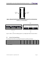
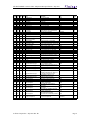
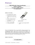
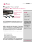
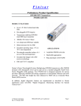
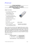
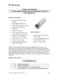
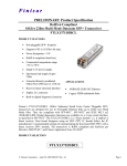
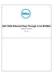
Product Specification
RoHS-6 Compliant
Laserwire™ SFP+ Adapter
FTLX0071D4BNL
PRODUCT FEATURES
•
Hot-pluggable SFP+ footprint
•
Supports Laserwire™ datarates
(1 Gbps to 10.3 Gbps)
•
RoHS-6 compliant (lead-free)
•
Extended temperature range
-5°C to 85°C
•
Single 3.3V power supply
•
Customizable EEPROM
APPLICATIONS
•
Adapts Laserwire™ plug for SFP+
ports
Finisar’s FTLX0071D4BNL 10Gb/s Laserwire™ SFP+ Adapters are designed for use in
conjunction with Finisar’s Laserwire cables (Part Numbers: FCBP110LD1Lxx and
FCBC110LD1Lxx). The FTLX0071D4BNL SFP+ Adapter allows a Laserwire cable to
be plugged into an SFP+ port. The SFP+ Adapter incorporates a customizable EEPROM.
The Adapter is RoHS compliant and lead free per Directive 2002/95/EC1, and Finisar
Application Note AN-20382.
PRODUCT SELECTION
FTLX0071D4BNL
© Finisar Corporation - July 2010 Rev. B1
Page 1
FTLX0071D4BNL Laserwire SFP+ Adapter Product Specification –July 2010
I.
Background
Figure 1 illustrates the application of the FTLX0071D4BNL SFP+ Adapter. Pin
descriptions for the FTLX0071D4BNL interface to the host board are shown in Section
II. Please refer to the FCBP110LD1Lxx Laserwire datasheet for details of the interface
between the FTLX0071D4BNL SFP+ Adapter and the Laserwire cable. The Laserwire
connector pin-out is also shown in Section II for reference.
Label
Laserwire™
FCBP110LD1Lxx
SFP+ Adapter
FTLX0071D4BNL
SFP+ port/cage on host board
Figure 1. (Top View) From left to right: Laserwire, SFP+ Adapter, SFP+ cage on host board.
Insertion sequence: (1) SFP+ Adapter is plugged into SFP+ port; (2) Laserwire is plugged
into Adapter.
Extraction sequence: (1) Depress tab on top of Laserwire plug and extract cable from
Adapter; (2) Pull on Adapter bail release lever and extract Adapter from host port.
© Finisar Corporation - July 2010 Rev. B1
Page 2
FTLX0071D4BNL Laserwire SFP+ Adapter Product Specification –July 2010
II.
Pin Descriptions
Pin
Symbol
Name/Description (per SFF-8431)
Laserwire-Adapter Interface
1
Transmitter Ground
Connected to Laserwire VEE
2
VEET
TFAULT
Adapter-SFP+ Port
Interface
Pass through
Transmitter Fault
NC
Pulled low in adapter
2
3
TDIS
Transmitter Disable
NC
3
4
SDA
2-wire Serial Interface Data line
NC
5
SCL
2-wire Serial Interface Clock
NC
6
7
8
9
10
MOD_ABS
RS0
RX_LOS
RS1
VEER
Module Absent
Rate Select 0
Receiver Loss of signal (active high)
Rate Select 1
Receiver Ground
NC
NC
Connected to Laserwire Fault output pin 6
Connected to Laserwire VEE
NC
Connected to adapter
EEPROM
Connected to adapter
EEPROM
Pulled low in adapter
NC
Pass through
NC
Pass through
11
12
13
14
VEER
RXRX+
VEER
Connected to Laserwire VEE
DC Coupled to Laserwire RX- pin 11
DC Coupled to Laserwire RX+ pin 10
Connected to Laserwire VEE
Pass through
Pass through
Pass through
Pass through
1
15
VCCR
Connected to Laserwire VCC pin 5
Pass through
16
VCCT
Connected to Laserwire VCC pin 5
Pass through
17
18
19
20
VEET
TX+
TXVEET
Receiver Ground
Receiver Inverted DATA out
Receiver Non-inverted DATA out
Receiver Ground
Receiver Power Supply
(+3.3V ± 5%)
Transmitter Power Supply
(+3.3V ± 5%)
Transmitter Ground
Transmitter Non-Inverted DATA in
Transmitter Inverted DATA in
Transmitter Ground
Connected to Laserwire VEE
DC Coupled to Laserwire TX+ pin 3
DC Coupled to Laserwire TX- pin 2
Connected to Laserwire VEE
Pass through
Pass through
Pass through
Pass through
Notes:
1. Circuit ground is internally isolated from chassis ground.
2. Open collector output. Should be pulled up with 4.7k - 10 kΩ on host to VccHost
3. Open collector input pin. Should be pulled up with 4.7k - 10 kΩ on module to VccT
4. See 2-wire electrical specifications in SFF-8431 section 4.2
5. Should be pulled up with 4.7k - 10 kΩ on host to VccHost
© Finisar Corporation - July 2010 Rev. B1
Page 3
Note
1
4
4
5
2
1
1
1
1
FTLX0071D4BNL Laserwire SFP+ Adapter Product Specification –July 2010
1
VeeT
2
TX_Fault
TD-
1
9
TD+
1
8
VeeT
1
7
VccT
16
VccR
15
VeeR
1
4
RD+
13
RD-
1
2
Vee
R
1
1
TX_Disable
3
SDA
4
Towards
Bezel
2
0
5
SCL
6
Towards
ASIC
MOD_ABS
7
RS0
8
RX_LOS
9
RS1
10
VeeR
Figure 1. Diagram of Host Board Connector Block Pin Numbers and Names, for pin-out reference.
Details of host-board connector specifications can be found in SFF-84313. Or refer to Finisar SFP+
datasheet (e.g., FTLX8571D3BCL)
Towards
1
TX-
Vee
-
12
11
10
9
-
8
Cable End View
7
6
5
4
3
Vee
2
TX+
TX
3
Vee
TX+
4
Vcc
Vee
5
F
Vcc
6
Fault
7
NC
Res
8
Cab
Abs
Cab Abs
9
Vee
Vee
10
RX+
RX+
11
RX -
RX
12
Vee
Vee
Bezel
2
1
-
Towards
ASIC
(a)
(b)
Figure 2. Pinout : (a) Laserwire cable plug end view, (b) Adapter pin-out (Laserwire port endview).
III.
Absolute Maximum Ratings
Exceeding the limits below may damage the transceiver module permanently.
Parameter
Maximum Supply Voltage
Storage Temperature
Relative Humidity
Symbol
Vcc
TS
RH
Min
-0.5
-40
0
Typ
Max
4.0
85
85
Unit
V
°C
%
Ref.
1
1. Non-condensing.
© Finisar Corporation - July 2010 Rev. B1
Page 4
FTLX0071D4BNL Laserwire SFP+ Adapter Product Specification –July 2010
IV.
Electrical Characteristics (TOP = -5 to 85°C, VCC = 3.14 to 3.46 Volts)
Electrical characteristics assume a Laserwire cable is inserted into the Adapter port.
Parameter
Supply Voltage
Supply Current
Transmitter (to Laserwire)
Differential data input swing
Receiver (from Laserwire)
Differential data output swing
Power Supply Ripple Tolerance
Symbol
Vcc
Icc
Min
3.14
Vin,pp
180
Vout,pp
PSR
450
33
Typ
150
700
Max
3.46
200
Unit
V
mA
Ref.
800
mV
1
850
mV
mVpp
2
4
Notes:
1. AC coupled internally. See Figure 2 of Laserwire (P/N FCBP110LD1Lxx) Datasheet for input eye
mask requirements. Self-biasing 100Ω differential input.
2. AC Coupled with 100Ω differential output impedance. See Figure 3 of Laserwire (P/N
FCBP110LD1Lxx) Datasheet for output eye mask.
3. All transceiver specifications are guaranteed with the given power supply sinusoidal modulation up to
specified amplitude over a range of 10 Hz to 10 MHz applied through the power supply filtering
network shown in Figure 6. See SFF-8431 Rev 2.2 (SFP+) specification section D.17.3 Power Supply
Tolerance Testing for the test methodology but with the module replaced by a 15Ω load for amplitude
calibration.
V.
Environmental Specifications
The FTLX0071D4BNL SFP+ Adapter has an operating temperature range from -5°C to
+85°C case temperature. Note that the Laserwire™ cable has an operating temperature
range of 0°C to +60°C.
Parameter
Case Operating Temperature
Storage Temperature
VI.
Symbol
Top
Tsto
Min
-5
-40
Typ
Max
85
85
Units
°C
°C
Ref.
Regulatory Compliance
These products are certified by TÜV and CSA to meet the Class 1 eye safety
requirements of EN (IEC) 60825 and the electrical safety requirements of
EN (IEC) 60950. Copies of certificates are available at Finisar Corporation upon request.
© Finisar Corporation - July 2010 Rev. B1
Page 5
FTLX0071D4BNL Laserwire SFP+ Adapter Product Specification –July 2010
VII.
Mechanical Specifications
Finisar’s Laserwire SFP+ Adapters are compatible with the dimensions defined by the
SFP+ Mechanical Specifications in SFF-84324, with the exception of the port design to
accommodate the Laserwire plug.
Figure 3. FTLX0071D4BNL Mechanical Dimensions.
© Finisar Corporation - July 2010 Rev. B1
Page 6
FTLX0071D4BNL Laserwire SFP+ Adapter Product Specification –July 2010
VIII. EEPROM Table (Address A0h)
Byte
Bit
Addr Hex LSB Size Name
0
00
0
8 Identifier
1
2
01
02
0
0
8
8
Ext_Identifier
Connector
Description
Type of serial transciever
Extended identifier of type of serial
transceiver
Code for connector type
3
3
3
3
3
3
3
3
4
4
4
4
4
4
4
4
5
5
5
5
5
5
5
5
6
6
6
6
6
6
6
6
7
7
7
7
7
7
7
7
8
8
8
8
8
8
8
8
9
9
9
9
9
9
9
9
03
03
03
03
03
03
03
03
04
04
04
04
04
04
04
04
05
05
05
05
05
05
05
05
06
06
06
06
06
06
06
06
07
07
07
07
07
07
07
07
08
08
08
08
08
08
08
08
09
09
09
09
09
09
09
09
0
1
2
3
4
5
6
7
0
1
2
3
4
5
6
7
0
1
2
3
4
5
6
7
0
1
2
3
4
5
6
7
0
1
2
3
4
5
6
7
0
1
2
3
4
5
6
7
0
1
2
3
4
5
6
7
1
1
1
1
1
1
1
1
1
1
1
1
1
1
1
1
1
1
1
1
1
1
1
1
1
1
1
1
1
1
1
1
1
1
1
1
1
1
1
1
1
1
1
1
1
1
1
1
1
1
1
1
1
1
1
1
Transceiver - 1X Copper Passive
Transceiver - 1X Copper Active
Transceiver - 1X LX
Transceiver - 1X SX
Transceiver - 10G Base-SR
Transceiver - 10G Base-LR
Transceiver - 10G Base-LRM
Unallocated
OC 48 short reach
OC 48 intermediate reach
OC 48 long reach
SONET reach specifier bit 2
SONET reach specifier bit 1
OC 192 short reach
ESCON SMF, 1310nm Laser
ESCON MMF, 1310nm LED
OC 3, short reach
OC 3, single mode inter.reach
OC 3, single mode long reach
Reserved
OC 12, short reach
OC 12, single mode inter.reach
OC 12, single mode long reach
Reserved
1000BASE-SX
1000BASE-LX
1000BASE-CX
1000BASE-T
100BASE-LX/LX10
100BASE-FX
BASE-BX10
BASE-PX
Electrical inter-enclosure
Longwave laser
Reserved
Medium distance (M)
Long distance (L)
Intermediate distance (I)
Short distance (S)
Very long distance (V)
Reserved
Copper FC-BaseT
Copper Passive
Copper Active
Longwave Laser (LL)
Shortwave Laser with OFC (SL)
Shortwave Laser w/o OFC (SN)
Electrical inter-enclosure
Single mode (SM)
Reserved
Multimode, 50um (M5)
Multimode, 62.5um (M6)
Video Coax (TV)
Miniature Coax (MI)
Twisted Pair (TP)
Twin Axial Pair (TW)
Infiniband Compliance Codes
Infiniband Compliance Codes
Infiniband Compliance Codes
Infiniband Compliance Codes
10G Ethernet Compliance Codes
10G Ethernet Compliance Codes
10G Ethernet Compliance Codes
Unallocated
SONET Compliance Codes
SONET Compliance Codes
SONET Compliance Codes
SONET Compliance Codes
SONET Compliance Codes
SONET Compliance Codes
ESCON Compliance Codes
ESCON Compliance Codes
SONET Compliance Codes
SONET Compliance Codes
SONET Compliance Codes
Reserved
SONET Compliance Codes
SONET Compliance Codes
SONET Compliance Codes
Reserved
Ethernet Compliance Codes
Ethernet Compliance Codes
Ethernet Compliance Codes
Ethernet Compliance Codes
Ethernet Compliance Codes
Ethernet Compliance Codes
Ethernet Compliance Codes
Ethernet Compliance Codes
Fibre Channel transmitter technology
Fibre Channel transmitter technology
Reserved
Fibre Channel link length
Fibre Channel link length
Fibre Channel link length
Fibre Channel link length
Fibre Channel link length
Reserved
Fibre Channel transmitter technology
Fibre Channel transmitter technology
Fibre Channel transmitter technology
Fibre Channel transmitter technology
Fibre Channel transmitter technology
Fibre Channel transmitter technology
Fibre Channel transmitter technology
Fibre Channel transmission media
Reserved
Fibre Channel transmission media
Fibre Channel transmission media
Fibre Channel transmission media
Fibre Channel transmission media
Fibre Channel transmission media
Fibre Channel transmission media
© Finisar Corporation - July 2010 Rev. B1
Hex
Value
3
Value
SFP+
GBIC/SFP function is defined
by serial ID only
Unspecified
FALSE
FALSE
FALSE
TRUE
TRUE
FALSE
FALSE
TRUE
FALSE
FALSE
FALSE
FALSE
FALSE
FALSE
FALSE
FALSE
FALSE
FALSE
FALSE
0
0
0
1
1
0
0
1
0
0
0
0
0
0
0
0
0
0
0
FALSE
FALSE
FALSE
0
0
0
TRUE
FALSE
FALSE
FALSE
FALSE
FALSE
FALSE
FALSE
FALSE
FALSE
1
0
0
0
0
0
0
0
0
0
FALSE
FALSE
FALSE
TRUE
FALSE
0
0
0
1
0
FALSE
FALSE
FALSE
FALSE
FALSE
TRUE
FALSE
FALSE
0
0
0
0
0
1
0
0
TRUE
TRUE
FALSE
FALSE
FALSE
FALSE
1
1
0
0
0
0
4
0
Page 7
FTLX0071D4BNL Laserwire SFP+ Adapter Product Specification –July 2010
Byte
Bit
Addr Hex LSB Size Name
10
0A
0
1 100 Mbytes/sec
10
0A
1
1 RESERVED
10
0A
2
1 200 Mbytes/sec
10
0A
3
1 RESERVED
10
0A
4
1 400 Mbytes/sec
10
0A
5
1 RESERVED
10
0A
6
1 800 Mbytes/sec
10
0A
7
1 1200 Mbytes/sec
11
0B
0
8 Encoding
Description
Fibre Channel speed
RESERVED
Fibre Channel speed
RESERVED
Fibre Channel speed
RESERVED
Fibre Channel speed
Fibre Channel speed
Code for serial encoding algorithm
Value
FALSE
Hex
Value
0
FALSE
0
FALSE
0
FALSE
TRUE
64B/66B
0
1
6
103
Unspecified
0
0
67
0
0
0
12
13
14
15
0C
0D
0E
0F
0
0
0
0
8
8
8
8
BR, Nominal
Rate Identifier
Length (9μm) - km
Length (9μm)
Nominal bit rate, units of 100 Mbits/sec
Rate selection functionality
Link length 9μm fiber, units of km
Link length 9μm fiber, units of 100m
16
10
0
8
Length (50μm, OM2)
17
18
11
12
0
0
8
8
Length (62.5μm, OM1)
Length (Copper)
Link length 50μm/OM2 fiber, units of 10m 8
Link length 62.5μm/OM1 fiber, units of
10m
3
Link length copper, units of meters
0
3
0
19
…
64
64
…
65
65
65
65
13
0
8
Length (50μm, OM3)
Link length 50μm/OM3 fiber, units of 10m 3
3
40
40
0
1
1
1
Options_Rx output
Options_Power class
Limiting = False, Linear = True
Class 1 = False, Class 2 = True
FALSE
FALSE
0
0
41
41
41
41
1
2
3
4
1
1
1
1
Options-Rx_LOS
Options-Rx_LOS
Options-Tx_FAULT
Options-Tx_DISABLE
TRUE
FALSE
FALSE
FALSE
1
0
0
0
65
65
66
67
…
41
41
42
43
5
6
0
0
1
2
8
8
Options-RATE_SELECT
RESERVED
BR, max
BR, min
Rx_LOS implemented, per SFP MSA
Rx_LOS implemented, signal inverted
Tx_FAULT signal implemented
Tx_DISABLE implemented
RATE_SELECT implemented, per SFP
MSA
RESERVED
Upper bit rate margin, units of %
Lower bit rate margin, units of %
FALSE
0
0
0
0
0
92
5C
2
1
Diagnostic Monitoring Type
FALSE
0
92
92
92
5C
5C
5C
3
4
5
1
1
1
Diagnostic Monitoring Type
Diagnostic Monitoring Type
Diagnostic Monitoring Type
FALSE
FALSE
TRUE
0
0
1
1
1
0
0
FALSE
FALSE
0
0
FALSE
0
FALSE
0
FALSE
0
FALSE
0
92
5C
6
1
Diagnostic Monitoring Type
92
93
93
93
5C
5D
5D
5D
7
0
1
2
1
1
1
1
Diagnostic Monitoring Type
RESERVED
Enhanced Options
Enhanced Options
93
5D
3
1
Enhanced Options
93
5D
4
1
Enhanced Options
93
5D
5
1
Enhanced Options
93
5D
6
1
Enhanced Options
93
5D
7
1
Enhanced Options
94
…
5E
0
8
SFF-8472 Compliance
© Finisar Corporation - July 2010 Rev. B1
Address change required see section
above, "addressing modes"
Received power measurement type; 0 =
OMA, 1 = Average Power
Externally calibrated
Internally calibrated
Digital diagnostic monitoring implemented
(described in this document). Must be '1'
for compliance with this document
implementations. Must be '0' for
compilance with this document.
RESERVED
Rate Select control implemented
Application Select control implemented
Optional Soft RATE_SELECT control and
monitoring implemented
Optional Soft RX_LOS monitoring
implemented
Optional Soft TX_FAULT monitoring
implemented
Optional Soft TX_DISABLE control and
monitoring implemented
Optional Alarm/Warning flags
implemented for all monitored quantities FALSE
Indicates which revision of SFF-8472 the
transceiver complies with
Not Included
8
0
0
Page 8
FTLX0071D4BNL Laserwire SFP+ Adapter Product Specification –July 2010
IX.
References
1. Directive 2002/95/EC of the European Council Parliament and of the Council, “on
the restriction of the use of certain hazardous substances in electrical and electronic
equipment”. January 27, 2003.
2. “Application Note AN-2038: Finisar Implementation Of RoHS Compliant
Transceivers”, Finisar Corporation, January 21, 2005.
3. “Specifications for Enhanced 8.5 and 10 Gigabit Small Form Factor Pluggable
Module ‘SFP+ ‘”, SFF Document Number SFF-8431, Revision 2.0, April 26, 2007.
4. “Improved Pluggable Formfactor”, SFF Document Number SFF-8432, Revision 4.2,
April 18, 2007.
X.
For More Information
Finisar Corporation
1389 Moffett Park Drive
Sunnyvale, CA 94089-1133
Tel. 1-408-548-1000
Fax 1-408-541-6138
[email protected]
www.finisar.com
© Finisar Corporation - July 2010 Rev. B1
Page 9