Download Adtran XFP 10G 1550nm
Transcript
jobAid
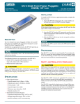
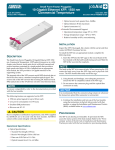
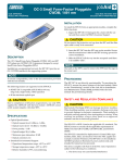
Small Form-Factor Pluggable
CLEI: BVL3AFKD_ _
Product P/N: 1442940G1C
10 Gigabit Ethernet XFP, 1550 nm,
Commercial Temperature
Issue Date: November 2010
Document P/N: 61442940G1C-22A
Operational Specifications
♦ Optical Specifications:
◊ Transmit Wavelength: 1550 nm
◊ Receive Wavelength: 1530 to 1565 nm
◊ Data rate: 9.95 Gb/s to 11.3 Gb/s
◊ Optical transmit level: –1 to +2 dBm
◊ Optical receive level: > –16 dBm
◊ Optical distance: 40 km maximum
◊ Optical connectors: LC
♦ Extended Environmental Support:
◊ Operational temperature range: 0°C to +70°C
◊ Storage temperature range: –40°C to +85°C
DESCRIPTION
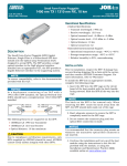
The 10 Gigabit Ethernet XFP, 1550 nm, Commercial Temperature (XFP) optical transceiver is a full duplex serial electric, serial optical device with both transmit and receive functions contained in a single module. The XFP provides a high speed serial link at 10 Gb/s. Installed into an appro‐
priate host module, the XFP provides a 10 Gigabit interface to the supporting system.
The transmit side of the XFP converts serial NRZ electrical date at the10 Gb/s line rate to a standard compliant optical signal. The receive side of the XFP converts the incoming DC balanced serial NRZ optical data at the 10 Gb/s line rate into serial electrical data.
NOTE
To ensure compatibility, refer to the documentation
provided with the host module.
The following features are supported on the XFP:
♦ 1550 nm optical signals for up to 40 km reach
♦ Case commercial temperature range from 0°C to 70°C
♦ Low power consumption (< 3 W max)
♦ Excellent EMI performance
!
CAUTION
Due to compliance certification requirements, only XFPs
supplied by ADTRAN are to be used with the host module.
ADTRAN cannot certify system integrity with other XFPs.
◊ Relative humidity to 85%, noncondensing
INSTALLATION
Inspect the XFP. If damaged, file a claim with the carrier and then contact ADTRAN Customer Service.
To install the XFP into an appropriate module, complete the following steps:
1. Insert the XFP into the XFP cage on the circuit board of the host module with the latch handle facing out‐
ward. Slide the XFP all the way into the receptacle.
NOTE
The latch on the XFP is for removal only. When removing
the XFP, rotate the latch away from the XFP cage until a
physical click occurs. The XFP should slide easily out of the
cage.
2. Using thumb and forefinger, exert adequate pressure to ensure the XFP is completely seated in the XFP cage.
3. Do not remove the connector plug until the optical fiber connection is made.
NOTICE
It is recommended that the connector plug remain on
whenever the transceiver optical fiber connector is not
inserted.
4. Continue the installation and turn‐up of the host module using the instructions in the Job Aid provided with that module, or using the Installation and Maintenance Practice (I&M), available online at www.adtran.com.
PROVISIONING
The XFP is not directly provisionable. To provision the XFP, access the menu system of the host module. Refer to the “Provisioning” section of the Job Aid or Installation and Maintenance Practice provided with the host module for provisioning details.
ground, the system would be intended for deployment
only in a DC‐C configuration.
♦ The ADTRAN system chassis frame ground terminal
must be connected to a reliable earth ground to ensure
that the metal enclosure of the XFP is properly
grounded via the backplane connector.
C
SAFETY AND REGULATORY COMPLIANCE
! CAUTION
♦ Electrostatic Discharge (ESD) can damage electronic
modules. When handling modules, wear an antistatic
discharge wrist strap to prevent damage to electronic
components. Place modules in antistatic packing
material when transporting or storing. When working
on modules, always place them on an approved
antistatic mat that is electrically grounded.
♦ The XFP meets or exceeds all the applicable
requirements of NEBS, Telcordia GR‐63‐CORE, and GR‐
1089‐CORE. The XFP is intended for deployment in
Central Office type facilities, EEEs, EECs, and locations
where the NEC applies (for example, Customer
Premises). The XFP is to be installed in ADTRAN
products in Restricted Access Locations only, and
installed by trained service personnel.
CAUTION
The XFP is a Class 1 Laser Product and complies with the
Laser Safety requirements of FDA 21CFR 1040.10 and
1040.11, and IEC60825‐1 and ‐2. The XFP is NRTL listed
and CB Certified to all applicable American and European
safety standards.
For continued compliance with the above laser safety
standards, only approved Class 1 modules from our
approved vendor list, located on the ADTRAN website,
should be installed in ADTRAN products.
NOTE
The Gigabit Ethernet port(s) are optical and therefore are
not classified as any type of port as defined in Appendix B
of GR‐1089‐CORE Issue 5.
The XFP is designed to meet the following environmental classes:
♦ ETSI EN 300 019‐1‐1 “Classification of environmental conditions; Storage,” Class 1.2
This device complies with FCC 47 CFR Part 15, Class B. Operation is subject to the following two conditions:
♦ ETSI EN 300 019‐1‐2 “Classification of environmental 1. This device may not cause harmful interference.
♦ ETSI EN 300 019‐1‐3 “Classification of environmental 2. This device must accept any interference received, including interference that may cause undesired operation.
Changes or modifications not expressly approved by ADTRAN could void the userʹs authority to operate this equipment.
!
CAUTION
♦ Per GR‐1089‐CORE, the ADTRAN system in which the
SFP is being deployed is designed and intended for
installation as part of a Common Bonding Network
(CBN). The ADTRAN system in which the SFP is being
deployed is not designed nor intended for installation as
part of an Isolated Bonding Network (IBN).
conditions, Transportation,” Class 2.3
conditions, Stationary use at weather‐protected locations,” Class 3.3
The equipment is designed to function without degra‐
dation during exposure to all test severities per Class 3.3 of ETSI EN 300 019‐1‐3.
The XFP meets EU RoHS Directive 2002/95/EC and/or applicable exemptions. Refer to www.adtran.com for further information on RoHS/WEEE.
♦ Per GR‐1089‐CORE Section 9, the XFP does not have an
internal DC connection between battery return and
frame ground. The XFP can be installed in a DC‐I
(isolated) or DC‐C (common) configuration. For
installations where other cards or the host system have
internal connections between battery return and frame
For more information, refer to the Installation and Maintenance Practice (P/N 61442940G1C-5)
available online at www.adtran.com.
Warranty: ADTRAN will replace or repair this product within the warranty period if it does not
meet its published specifications or fails while in service. Warranty information can
be found online at www.adtran.com/warranty.
©2010 ADTRAN, Inc. All Rights Reserved.
CAUTION!
SUBJECT TO ELECTROSTATIC DAMAGE
OR DECREASE IN RELIABILITY.
HANDLING PRECAUTIONS REQUIRED.
ADTRAN CUSTOMER CARE:
From within the U.S. 1.800.726.8663
From outside the U.S. +1 256.963.8716
PRICING AND AVAILABILITY 1.800.827.0807
*61442940G1C-22A*


