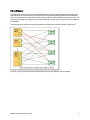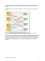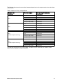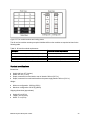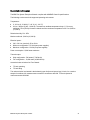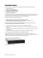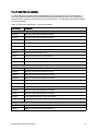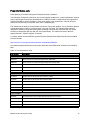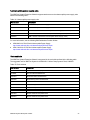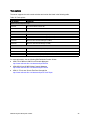
1
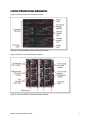
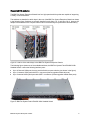
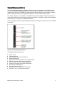
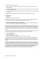
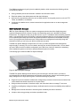
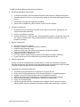
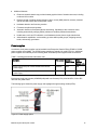
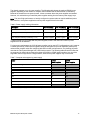
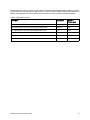
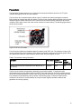
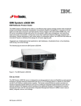
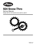
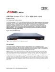
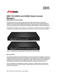
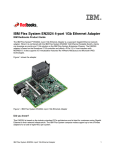
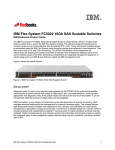
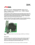
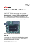
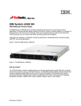
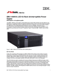
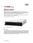
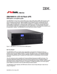
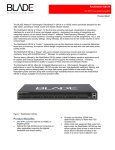
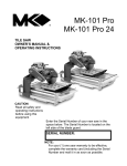
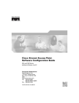
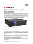
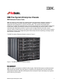
I BM ® IBM Flex System Enterprise Chassis IBM Redbooks Product Guide IBM Flex System™, a new category of computing and the next generation of Smarter Computing, is anchored by the IBM Flex System Enterprise Chassis. This platform offers intelligent workload deployment and management for maximum business agility. This chassis delivers high-speed performance complete with integrated servers, storage, and networking for multiple chassis management in data center compute environments. Furthermore, its flexible design can meet the needs of varying workloads with independently scalable IT resource pools for higher utilization and lower cost per workload. While increased security and resiliency protect vital information and promote maximum uptime, the integrated, easy-to-use management system reduces setup time and complexity, providing a quicker path to return on investment. The IBM Flex System Enterprise Chassis is shown in Figure 1. Figure 1. The IBM Flex System Enterprise Chassis Did you know? IBM Flex System is the platform for IBM® PureFlex System. IBM PureFlex System combines advanced IBM hardware and software along with patterns of expertise and integrates them into three optimized configurations, Express, Standard, and Enterprise, that are simple to acquire and deploy so you get fast time to value for your solution. IBM Flex System Enterprise Chassis 1 Key features The IBM Flex System Enterprise Chassis is a simple, integrated infrastructure platform that supports a mix of compute, storage, and networking resources to meet the demands of your applications. The solution is easily scalable with the addition of another chassis with the required nodes. With the IBM Flex System Manager, multiple chassis can be monitored from a single screen. The 14 node, 10U chassis delivers high-speed performance complete with integrated servers, storage, and networking. This flexible chassis is designed for a simple deployment now and to scale to meet your needs in the future. Flexibility and efficiency The 14 bays in the chassis allow the installation of compute or management nodes, with networking modules in the rear. A single chassis or a group of chassis can be fully customized to the specific needs of the computing environment. With support for POWER7® and Intel processor-based nodes, you can choose the architecture you need. IT can meet the needs of the business using a single system across multiple architectures and operating environments. The system monitors and manages power usage on all major chassis components so you have total control over power consumption. The chassis supports N+N or N+1 redundant power supplies, configurable in either a single or three-phase power domain and an entirely passive mid-plane to meet your reliability needs. The power supplies are 80 PLUS Platinum-certified indicating high energy efficiency. The chassis design also optimizes cooling with cooling zones within the chassis. The system manages the fan modules based on node configuration within the chassis. So, the system can increase the speed of certain fan modules to cool potential hot spots, and use lower speeds for other fan modules where appropriate. Easily scalable with simple administration Because the IBM Flex System Enterprise Chassis is an all-in-one solution, it is designed for growth from a single chassis to many. Adding compute, storage, or networking capability is as simple as adding additional nodes, modules, or chassis. The simple, highly integrated management system allows you to use the Chassis Management Modules integrated into each chassis to administer a single chassis, or IBM Flex System Manager controls up to four chassis from a single panel. Designed for multiple generations of technology The IBM Flex System Enterprise Chassis is designed to be the foundation of your IT infrastructure now and into the future. Compute performance requirements are always on the rise and networking demands continue to grow with rising bandwidth needs and a shrinking tolerance for latency. The chassis is designed to scale to meet the needs of your future workloads, offering the flexibility to support current and future innovations in compute, storage, and networking technology. IBM Flex System Enterprise Chassis 2 Locations of key components and connectors Figure 2 shows the front of the Enterprise Chassis. Figure 2. Front of the IBM Flex System Enterprise Chassis Figure 3 shows the rear of the Enterprise Chassis. Figure 3. Rear of the IBM Flex System Enterprise Chassis IBM Flex System Enterprise Chassis 3 Standard specifications The following table lists the standard specifications. Table 1. Standard specifications Components Specification Model System x® ordering sales channel: 8721-A1x Power Systems™ sales channel: 7893-92X Form factor 10U rack-mounted unit. Maximum number of compute nodes supported 14 half-wide (single bay), seven full-wide (two bays), or three double-height full-wide (four bays). Mixing is supported. Chassis per 42U rack Four. Nodes per 42U rack 56 half-wide, or 28 full-wide. Management One or two Chassis Management Modules (CMMs), for basic chassis management. Two CMMs form a redundant pair; One CMM standard in 8721-A1x. The CMM interfaces with the integrated management module (IMM) or Flexible Service Processor (FSP) integrated in each compute node in the chassis. Optional IBM Flex System Manager management appliance for comprehensive management, including virtualization, networking, and storage management. I/O architecture Up to eight lanes of I/O to an I/O adapter card, with each lane capable of up to 16 Gbps bandwidth. Up to 16 lanes of I/O to a half-wide node with two adapters. A wide variety of networking solutions, including Ethernet, Fibre Channel, Fibre Channel over Ethernet (FCoE), and InfiniBand. Power supplies Six 2500W power modules that provide N+N or N+1 redundant power; Two standard in model 8721-A1x. Power supplies are 80 PLUS Platinum-certified and provide 95% efficiency at 50% load and 92% efficiency at 100% load. Power capacity of 2500W output rated at 200VAC. Each power supply contains two independently powered 40 mm (1.57 in) cooling fan modules. 2100W power supplies also available via CTO only and with restricted configurations. Fan modules Ten fan modules (eight 80 mm (3.14 in) fan modules and two 40 mm (1.57 in) fan modules); Four 80 mm and two 40 mm fan modules standard in model 8721-A1x. Dimensions Height: 440 mm (17.3 in) Width: 447 mm (17.6 in) Depth: 800 mm (31.5 in) (measured from front bezel to rear of chassis), 840 mm (33.1 in) (measured from node latch handle to the power supply handle) Weight Minimum configuration: 96.62 kg (213 lb) Maximum configuration: 220.45 kg (486 lb) Declared sound level 7.5 bels Temperature Operating air temperature 5°C to 40°C Electrical power Input power: 200 - 240 V ac (nominal), 50 or 60 Hz Minimum configuration: 0.51 kVA (two power supplies) Maximum configuration: 13 kVA (six power supplies) Power consumption 12,900 watts maximum IBM Flex System Enterprise Chassis 4 The IBM Flex System Enterprise Chassis model 8721-A1x ships with the following items: One Chassis Management Module Two 2500 W power supplies Four 80 mm Fan Modules Two 40 mm Fan Modules Four Power Supply Fillers One Console Breakout Cable Two C19 to C20 two-meter power cables One Rack Mount Kit Supported compute nodes The following table lists the compute nodes that are supported in the IBM Flex System Enterprise Chassis. The table also lists the maximum number installable. Table 2. Supported compute nodes and maximum quantities Description Machine type Maximum number of nodes per chassis IBM Flex System x220 Compute Node 7906 14 IBM Flex System x240 Compute Node 8737 14 IBM Flex System x440 Compute Node 7917 7 IBM Flex System p24L Compute Node 1457 14 IBM Flex System p260 Compute Node 7895-22X 14 IBM Flex System p460 Compute Node 7895-42X 7 IBM Flex System Manager Node 8731-A1x 1 (2 per four chassis) See IBM® ServerProven® at the following web address for the latest information about the servers supported in the IBM Flex System Enterprise Chassis: http://ibm.com/servers/eserver/serverproven/compat/us/ IBM Flex System Enterprise Chassis 5 Supported I/O modules The IBM Flex System Enterprise Chassis has four high-speed switch bays that are capable of supporting a variety of I/O architectures. The switches are installed in switch bays in the rear of the IBM Flex System Enterprise Chassis as shown in the following figure. Switches are normally installed in pairs (bays 1 & 2, and bays 3 & 4), because I/O adapter cards installed in the compute nodes route to two switch bays for performance and redundancy. Figure 4. Location of the switch bays in the IBM Flex System Enterprise Chassis The following figure shows one of the available switches, the IBM Flex System Fabric EN4093 10Gb Scalable Switch. It offers the following interface ports: Up to 42 internal 10Gb ports, three to each half-wide compute node bay (not shown in the figure) Up to 14 external 10Gb ports with SFP+ connectors (license upgrades enable all ports) Up to 2 external 40Gb uplink ports with QSFP+ connectors (license upgrades enable these ports) Figure 5. IBM Flex System Fabric EN4093 10Gb Scalable Switch IBM Flex System Enterprise Chassis 6 The following table lists the switches that are available for the chassis. Table 3. I/O modules and upgrades Part number System x feature code Power Systems feature code IBM Flex System Fabric CN4093 10Gb Converged Scalable Switch 00D5823 A3HH ESW2 IBM Flex System Fabric EN4093R 10Gb Scalable Switch 05Y3309 A3J6 ESW7 IBM Flex System Fabric EN4093 10Gb Scalable Switch 49Y4270 A0TB 3593 IBM Flex System EN4091 10Gb Ethernet Pass-thru 88Y6043 A1QV 3700 IBM Flex System EN2092 1Gb Ethernet Scalable Switch 49Y4294 A0TF 3598 IBM Flex System FC5022 16Gb SAN Scalable Switch 88Y6374 A1EH 3770 IBM Flex System FC5022 24-port 16Gb SAN Scalable Switch 00Y3324 A3DP ESW5 IBM Flex System FC5022 24-port 16Gb ESB SAN Scalable Switch 90Y9356 A1EJ 3771 IBM Flex System FC3171 8Gb SAN Switch 69Y1930 A0TD 3595 IBM Flex System FC3171 8Gb SAN Pass-thru 69Y1934 A0TJ 3591 90Y3450 A1EK 3699 Description Ethernet switches Fibre Channel switches InfiniBand switches IBM Flex System IB6131 InfiniBand Switch (QDR/FDR) IBM Flex System Enterprise Chassis 7 I/O architecture Each half-wide compute node (such as the IBM Flex System x240 Compute Node) has two adapter slots, and each full-wide compute node (such as the IBM Flex System x460 Compute Node) has four adapter slots. The adapter slots in each compute node route through the chassis midplane to the switch bays. The architecture supports up to eight ports per adapter although currently only two-port and four-port adapters are available. The following figure shows how two-port adapters are connected to switches installed in the chassis. Figure 6. Logical layout of the interconnects between two-port I/O adapters and I/O modules IBM Flex System Enterprise Chassis 8 A four-port adapter doubles the connections between each adapter and switch pair (for example, a four-port adapter in A1 in each compute node routes two connections to switch 1 and two connections to switch 2). The following figure shows how four-port adapters are connected to switches that are installed in the chassis. Figure 7. Logical layout of the inter-connections between four-port I/O adapters and I/O modules To make use of all four ports of a four-port card, you must install two switches in the chassis, and each switch must have 28 internal ports enabled. The IBM Flex System Fabric EN4093 10Gb Scalable Switch with license upgrade 1 enables 28 internal ports, for example. Similarly, when 6-port cards become available, two switches must be installed, and 42 internal ports must be enabled. The IBM Flex System Fabric EN4093 10Gb Scalable Switch with license upgrade 2 enables a total of 42 internal ports, for example. IBM Flex System Enterprise Chassis 9 The following table shows the connections between adapter slots in the compute nodes to the switch bays in the chassis. Table 4. Adapter to I/O bay correspondence I/O adapter slot in the server Port on the adapter Corresponding I/O module bay in the chassis Port 1 Module bay 1 Port 2 Module bay 2 Port 3 (for 4-port cards)* Module bay 1 Port 4 (for 4-port cards)* Module bay 2 Port 1 Module bay 3 Port 2 Module bay 4 Port 3 (for 4-port cards)* Module bay 3 Port 4 (for 4-port cards)* Module bay 4 Port 1 Module bay 1 Port 2 Module bay 2 Port 3 (for 4-port cards)* Module bay 1 Port 4 (for 4-port cards)* Module bay 2 Port 1 Module bay 3 Port 2 Module bay 4 Port 3 (for 4-port cards)* Module bay 3 Port 4 (for 4-port cards)* Module bay 4 Slot 1 Slot 2 Slot 3 (full-wide compute nodes only) Slot 4 (full-wide compute nodes only) * To make use of all four ports of a four-port adapter, the switch must have 28 internal ports enabled, and two switches must be installed in the bays as indicated. IBM Flex System Enterprise Chassis 10 Chassis Management Module The Chassis Management Module (CMM) provides single-chassis management. The CMM is used to communicate with the management controller in each compute node (IMMv2 in Intel processor-based compute nodes and FSP in POWER7® processor-based compute nodes) to provide system monitoring, event recording and alerts, and to manage the chassis, its devices, and the compute nodes. The chassis supports up to two CMMs. If one CMM fails, the second CMM can detect its inactivity and activate itself to take control of the system without any disruption. The CMM is central to the management of the chassis and is required in the Enterprise Chassis. The following figure shows the Chassis Management Module. See Figure 3 for the location of the CMM in the chassis. Figure 8. Chassis Management Module The CMM provides these functions: Power control Fan management Chassis and compute node initialization Switch management Diagnostics: chassis, I/O options, and compute nodes Resource discovery and inventory management Resource alerts and monitoring management Chassis and compute node power management Security policy management Role-based access control Support for up to 84 local CMM user accounts Support for up to 32 simultaneous sessions IBM Flex System Enterprise Chassis 11 The CMM has the following connectors: USB connection. This connection can be used for insertion of a USB media key for tasks, such as firmware updates. 10/100/1000 Mbps RJ45 Ethernet connection to connect to a management network. The CMM can be managed via this Ethernet port. Serial port (mini-USB) for local command-line interface (CLI) management. Use serial cable 90Y9338 for connectivity. The CMM has the following light-emitting diodes (LEDs) that provide the following information: Power-on LED Activity LED Error LED Ethernet port link and port activity LEDs The CMM also incorporates a reset button, which, when pressed, resets the CMM back to its default condition. It has two functions, depending on how long the button is pressed: When pressed for less than 5 seconds, the CMM restarts. When pressed for more than 5 seconds (for example, 10 or 15 seconds), the CMM configuration is reset to the manufacturing defaults, and then the CMM restarts. The CMM supports a web-based graphical user interface (GUI) that provides a way to perform CMM functions within a supported web browser. You can also perform management functions through the CMM command-line interface (CLI). Both the web-based GUI and the CLI are accessible via the single RJ45 Ethernet connector on the CMM or from any other system that is connected to the same (management) network. The CMM has the following default static IPv4 address. By default, the CMM is configured to respond to Dynamic Host Configuration Protocol (DHCP) first before using its static IPv4 address: IP address: 192.168.70.100 Subnet: 255.255.255.0 User ID: USERID (all capital letters) Password: PASSW0RD (all capital letters, with a zero instead of the letter O) The CMM does not have a fixed static IPv6 IP address, by default. Initial access to the CMM in an IPv6 environment can be performed by either using the IPv4 IP address or the IPv6 link-local address. The IPv6 link-local address is automatically generated based on the Media Access Control (MAC) address of the CMM. The CMM is the key component enabling the integrated management network. Internally, the CMM has a multiple port L2 1Gigabit Ethernet switch with dedicated links to all 14 node bays, all four switch bays, and the second CMM, if installed. These connections are all point-to-point, ensuring dedicated bandwidth. The 1GbE links are full-duplex, fixed speed (not auto-negotiate) links. The 1 GbE management network is only accessible by each node's management controller (IMMv2 or FSP), each switch module's management interfaces, the CMM, and the IBM Flex System Manager (FSM) management appliance. This design permits the separation of the management network from the data network. IBM Flex System Enterprise Chassis 12 The CMM has a high-security policy that is enabled by default, which means that the following policies are enabled by default: Strong password policies with automatic validation and verification checks Required update of the default passwords after the initial setup Only secure communication protocols, such as SSH and SSL. Unencrypted protocols, such as HTTP, Telnet, and SNMPv1, are disabled. Certificates to establish secure, trusted connections for applications that run on the management processors IBM Flex System Manager IBM Flex System Manager (FSM) is a systems management solution that offers flexible integrated systems management across compute, storage, and networking resources in the IBM Flex System infrastructure. It is designed to help you get the most out of your IT installation while automating repetitive tasks. It can significantly reduce the number of manual navigational steps for typical management tasks. From simplified system setup procedures with wizards and built-in expertise to consolidated monitoring for all of your physical and virtual resources, FSM provides core management functionality along with automation so that you can focus your efforts on business innovation. The IBM Flex System Manager compute node, 8731-A1x, provides configuration and management support locally or remotely, for up to four chassis, their devices, and the compute nodes. You can install up to two FSMs in each four-chassis configuration (one FSM in two of the four chassis) for redundancy, which enables the system to continue to operate without disruption if one fails. The following figure shows the IBM Flex System Manager. Figure 9. IBM Flex System Manager The IBM Flex System Manager drives efficiency and cost savings in the data center. It provides a pre-integrated and virtualized management environment across servers, storage, and networking that is easily managed from a single pane of glass. It offers the following key features: Single focus point for seamless multichassis management provides an instant resource-oriented view of the chassis and chassis resources for compute nodes. Design reduces the number of interfaces, steps, and clicks that it takes to manage IT resources. Capability to intelligently manage and deploy workloads based on resource availability and predefined policies. Management of events and alerts to increase system availability and reduce downtime. It helps to drive energy savings and reduce operational costs. IBM Flex System Enterprise Chassis 13 The IBM Flex System Manager offers these main features: Monitoring and problem determination: A real-time multichassis view of hardware components with overlays for additional information Automatic detection of issues in your environment through an event setup that triggers alerts and actions Identification of changes that might affect availability Server resource utilization by virtual machine or across a rack of systems Hardware management: Automated discovery of physical and virtual servers and interconnections, applications, and supported third-party networking Inventory of hardware components Chassis and hardware component views, including hardware properties, component names and part numbers, firmware levels, energy usage and power consumption, utilization rates, and temperature readings Network management: Management of network switches Discovery, inventory, and status monitoring of switches Graphical network topology views Support for KVM, pHyp, and VMware virtual switches, and physical switches Virtual LAN (VLAN) configuration of switches Integration with server management Per-virtual machine network usage and performance statistics provided to VMControl Logical views of servers and network devices grouped by subnet and VLAN Storage management: Storage can also be consolidated onto the FSM platform, or users can virtualize the integrated enterprise storage with other multivendor storage systems within the existing environment, and then control all virtualized storage resources from the IBM Flex System platform. Virtualization and workload management: Consolidate physical infrastructure or applications onto fewer servers Deploy new or existing workload onto Linux, Microsoft Windows, or competitive platforms Upgrade current rack or blade infrastructure to an integrated environment Optimize the performance of applications by migrating them to Flex System Manager Move into advanced stages of virtualization or a private cloud deployment Deploy new workloads rapidly Optimize or upgrade high-value, noninfrastructure workloads, such as enterprise resource planning (ERP), customer relationship management (CRM), data warehousing, or analytics IBM Flex System Enterprise Chassis 14 Additional features: Resource-oriented chassis map provides instant graphical view of chassis resources, including nodes and I/O modules Remote console, including remote keyboard, video, mouse (KVM) session, remotely mounted optical and USB media, and remote power control Hardware detection and inventory creation Firmware compliance and updates Automatic detection of hardware failures and alerting. Capability to take corrective action, including automatically notifying IBM of problems to escalate problem determination Health status, such as CPU utilization, on all hardware devices from a single chassis view Administrative capabilities, such as setting up users within profile groups, assigning security levels, and security governance Power supplies A maximum of six power supplies can be installed in the Enterprise Chassis. Either 2500W or 2100W power supplies are available. Two 2500W power supplies are standard in model 8721-A1x. Additional power supplies are orderable per the following table. All installed power supplies must be the same. Table 5. Ordering part number and feature code Description Part number System x Feature code Power Systems Feature code IBM Flex System Enterprise Chassis 2500W Power Module (1 power supply) 43W9049 A0UC 3590 IBM Flex System Enterprise Chassis 2100W Power Module (1 power supply) 47C7633 A3JH None Each power supply part number (43W9049) ships with one 2-meter (6.5 ft) 16A/100-250V, C19 to IEC 320-C20 rack power cable. The following figure shows the power supply and highlights the light-emitting diodes (LEDs). Figure 10. Power supply option IBM Flex System Enterprise Chassis 15 Both power supplies are 80 PLUS Platinum-certified. The 2500W modules are 2500 Watts output rated at 200VAC to 208VAC (nominal), and 2750W at 220VAC to 240VAC (nominal). The power supply has an oversubscription rating of up to 3538 Watts output at 200VAC. The power supply operating range is 200-240 VAC. The power supplies also contain two dual independently powered 40mm cooling fan modules that are powered not from the power supply itself, but from the chassis midplane. The fan modules are variable speed and controlled by the chassis fan logic. The 2100W power supplies are 2100 Watts output power rated at 200-240VAC. Similar to the 2500W unit, this power supply also supports oversubscription, the 2100W unit can run up to 2895W for short duration. The 2100W supplies have two independently powered dual 40mm cooling fans, that pick up power from the midplane included within the power supply assembly. 80 PLUS is a performance specification for power supplies used within servers and computers. To meet the 80 PLUS standard, the power supply must have an efficiency of 80% or greater, at 20%, 50%, and 100% of rated load with PF of .09 or greater. The standard has several grades, such as Bronze, Silver, Gold, and Platinum. More information on 80 PLUS is available at http://www.80PLUS.org. With 2500W power supplies, the chassis allows configurations of power supplies to give N+N or N+1 redundancy. A fully configured chassis operates on only three 2500W power-supply units (PSUs) with no redundancy, but N+1 or N+N is advised. Three power supplies (or six with N+N redundancy) allow for a balanced three-phase configuration. All power supply modules are combined into a single power domain within the chassis, which distributes power to each of the compute nodes, I/O modules, and ancillary components through the Enterprise Chassis midplane. The midplane is a highly reliable design with no active components. Each power supply is designed to provide fault isolation and is hot swappable. In the case of the 2500W supplies, power monitoring of both the DC and AC signals allows the Chassis Management Module to accurately monitor the power supplies. Power monitoring with the 2100W power supplies is planned to be made available at a later date. The following figure shows the compute node bay numbering (left) and power supply bay numbering (right). Figure 11. Power supply bay numbering IBM Flex System Enterprise Chassis 16 The chassis supports up to six power supplies. The following table shows the required 2500W power supplies, depending on the number of compute nodes installed and the desired level of redundancy. Because the chassis has one power domain, it does not matter where the power supplies are installed. However, it is advised that you install the power supplies starting from the bottom power supply bays. Note: The use of high-performance or heavily-configured compute nodes can require additional power and, therefore, more power supplies than those power supplies listed in the table. Table 6. Power supply ordering information Description No redundancy N+1 redundancy N+N redundancy Up to four half-wide compute nodes (node bays 1 - 4) 1 power supply* 2 power supplies 2 power supplies Up to eight half-wide compute nodes (node bays 1 8) 2 power supplies 3 power supplies 4 power supplies All 14 compute node bays (node bays 1 - 14) 3 power supplies 4 power supplies 6 power supplies * Chassis model 8721-A1x ships with two power supplies, which is the minimum number of power supplies that can be installed. For low-power requirements, the 2100 W power supplies can be used (CTO configurations only), however a chassis powered by 2100W power supplies cannot be designated to provide redundant power (N+N) unless all the compute nodes are configured with 95W or lower Intel processors. For planning purposes note that the Flex System Manager has a 95W Intel processor. The following table shows the nodes that are supported in chassis when powered by either the 2100W or 2500W power supplies. Any mix of the supported nodes is supported in a single chassis, however the power supplies may not be mixed. Table 7. Compute node support by power supply Nodes 2100W power supplies 2500W power supplies Flex System Manager Yes Yes x220 (with or without the PEN or SEN) Yes* Yes x240 (with or without the PEN or SEN) Yes* Yes x440 Yes* Yes p24L No Yes p260 No Yes p460 No Yes V7000 Storage Node (with or without expansion node) Yes Yes * N+N redundancy is only possible if all installed compute nodes use Intel processors with a TDP of 95W or lower. IBM Flex System Enterprise Chassis 17 Each power supply option includes a power cable. Each power supply standard with the chassis includes a power cable. It is a 2-meter (6.5 ft) 16A/100-250V, C19 to IEC 320-C20 Rack Power Cable, feature code 6292. Other supported line cords including three-way split line cords, are listed in the following table. Table 8. Supported line cords Description Part number System x Feature code 4.3m, 16A/208V, C19 to NEMA L6-20P (US) Line Cord 40K9772 6275 2.5m, 16A/100-240V, C19 to IEC 320-C20 Rack Power Cable 39Y7916 6252 2m, 16A/100-250V, C19 to IEC 320-C20 Rack Power Cable None 6292 4.3m, US/CAN, NEMA L15-30P - (3P+Gnd) to 3X IEC 320 C19 00D7192 A2Y3 4.3m, EMEA/AP, IEC 309 32A (3P+N+Gnd) to 3X IEC 320 C19 00D7193 A2Y4 4.3m, A/NZ, (PDL/Clipsal) 32A (3P+N+Gnd) to 3X IEC 320 C19 00D7194 A2Y5 IBM Flex System Enterprise Chassis 18 Fan modules The Enterprise Chassis supports up to a total of ten hot-swap fan modules: two 40 mm (1.57 in) fan modules and eight 80 mm (3.14 in) fan modules. The two 40 mm fan modules distribute airflow to the I/O modules and chassis management modules. Both of these fan modules ship with the chassis. The 80 mm fan modules distribute airflow to the compute nodes through the chassis from front to rear. Each 80 mm fan module actually contains two 80 mm fan modules, back to back at each end of the module, which are counter-rotating. The following figure shows the 80 mm fan module. Figure 12. 80 mm fan module Four 80 mm fan modules are installed standard in chassis model 8721-A1x. The maximum number of 80 mm fan modules that can be installed is eight. Ordering information is shown in the following table. When the modules are ordered as a part number or feature code, they are supplied as a pair. Table 9. Fan module ordering information Description Part number System x Feature code Power Systems Feature code IBM Flex System Enterprise Chassis 80mm Fan Module Pair (2 fan modules) 43W9078 7805 A0UA The 80 mm fan modules are populated, depending on the nodes installed. To support the base configuration and up to four nodes, chassis model 8721-A1x ships with four 80 mm fan modules and two 40 mm fan modules preinstalled. There are two cooling zones for the nodes: a left zone and a right zone. Fan modules must be installed in pairs as shown in the following figure. If there are insufficient fan modules for the number of nodes installed, the compute nodes might be throttled to balance heat generation and cooling capacity. IBM Flex System Enterprise Chassis 19 Figure 13. Fan module locations and cooling zones The 40 mm fan modules are always required. Additional 80 mm fan modules are required as listed in the following table. Table 10. 80 mm fan module requirements Description 80 mm fan module requirements Up to four half-wide compute nodes (node bays 1 - 4) 4 fan modules (fan bays 1, 2, and 6, 7) Up to eight half-wide compute nodes (node bays 1 - 8) 6 fan modules (fan bays 1, 2, 3 and 6, 7, 8) All 14 compute node bays (node bays 1 - 14) 8 fan modules (fan bays 1, 2, 3, 4 and 6, 7, 8, 9) Physical specifications Dimensions: Height: 440 mm (17.3 inches) Width: 447 mm (17.6 in) Depth, measured from front bezel to rear of chassis: 800 mm (31.5 in) Depth, measured from node latch handle to the power supply handle: 840 mm (33.1 in) Weight: Minimum configuration: 96.62 kg (213 lb) Maximum configuration: 220.45 kg (486 lb) Shipping dimensions (approximate): Height: 81 cm (32 in) Length: 102 cm (40 in) Width: 71 cm (24 in) IBM Flex System Enterprise Chassis 20 Supported environment The IBM Flex System Enterprise Chassis complies with ASHRAE Class A3 specifications. The following environment is the supported operating environment. Temperature: 0 - 914 m (0 - 3,000 ft): 5 - 40 °C (41 - 104 °F) 914 m - 3048 m (3,000 - 10,000 ft): The maximum ambient temperature drops 1 °C for every additional 178 m (584 ft) increase in altitude until the maximum temperature is 28 °C at 3,048 m (10,000 ft) Relative humidity: 8% - 85% Maximum altitude: 3,048 m (10,000 ft) Electrical power: 200 - 240 V ac (nominal), 50 or 60 Hz Minimum configuration: 0.51 kVA (two power supplies) Maximum configuration: 13 kVA (six power supplies) Power consumption: 12,900 watts maximum Thermal output: Ship configuration - 500 watts (1,700 Btu/hr) Full configuration - 12,900 watts (43,900 Btu/hr) Acoustical noise emissions for Flex Chassis: 7.5 bels operating 7.5 bels idling The noise emission level stated is the declared (upper limit) sound power level, in bels, for a random sample of machines. All measurements are made in accordance with ISO 7779 and reported in conformance with ISO 9296. IBM Flex System Enterprise Chassis 21 Warranty options The IBM Flex System Enterprise Chassis has a three-year on-site warranty with 9x5 next-business-day terms. IBM offers the warranty service upgrades through IBM ServicePac®, discussed in this section. The IBM ServicePac is a series of prepackaged warranty maintenance upgrades and post-warranty maintenance agreements with a well-defined scope of services, including service hours, response time, term of service, and service agreement terms and conditions. IBM ServicePac offerings are country-specific. That is, each country might have its own service types, service levels, response times, and terms and conditions. Not all covered types of ServicePac might be available in a particular country. For more information about IBM ServicePac offerings available in your country, see the IBM ServicePac Product Selector at https://www-304.ibm.com/sales/gss/download/spst/servicepac. The following table explains warranty service definitions in more detail. Table 11. Warranty service definitions Term Description IBM on-site repair (IOR) A service technician will come to the server's location for equipment repair. 24x7x2 hour A service technician is scheduled to arrive at your client’s location within two hours after remote problem determination is completed. We provide 24-hour service, every day, including IBM holidays. 24x7x4 hour A service technician is scheduled to arrive at your client’s location within four hours after remote problem determination is completed. We provide 24-hour service, every day, including IBM holidays. 9x5x4 hour A service technician is scheduled to arrive at your client’s location within four business hours after remote problem determination is completed. We provide service from 8:00 a.m. to 5:00 p.m. in the client's local time zone, Monday through Friday, excluding IBM holidays. If after 1:00 p.m., it is determined that on-site service is required, the client can expect the service technician to arrive the morning of the following business day. For noncritical service requests, a service technician will arrive by the end of the following business day. 9x5 next business day A service technician is scheduled to arrive at your client’s location on the business day after we receive your call, following remote problem determination. We provide service from 8:00 a.m. to 5:00 p.m. in the client's local time zone, Monday through Friday, excluding IBM holidays. In general, the following types are the types of IBM ServicePacs: Warranty and maintenance service upgrades: One, two, three, four, or five years of 9x5 or 24x7 service coverage On-site repair from the next business day to four or two hours One or two years of warranty extension Remote technical support services: One or three years with 24x7 coverage (severity 1) or 9 - 5 next business day for all severities Installation and start-up support for System x servers Remote technical support for System x servers Software support - Support Line: Microsoft or Linux software VMware IBM Systems Director IBM Flex System Enterprise Chassis 22 Regulatory compliance The server conforms to the following standards: ASHRAE Class A3 FCC - Verified to comply with Part 15 of the FCC Rules Class A Canada ICES-004, issue 3 Class A UL/IEC 60950-1 CSA C22.2 No. 60950-1 NOM-019 Argentina IEC 60950-1 Japan VCCI, Class A IEC 60950-1 (CB Certificate and CB Test Report) China CCC (GB4943); (GB9254, Class A); (GB17625.1) Taiwan BSMI CNS13438, Class A; CNS14336 Australia/New Zealand AS/NZS CISPR 22, Class A Korea KN22, Class A, KN24 Russia/GOST ME01, IEC 60950-1, GOST R 51318.22, GOST R 51318.249, GOST R 51317.3.2, GOST R 51317.3.3 CE Mark (EN55022 Class A, EN60950-1, EN55024, EN61000-3-2, EN61000-3-3) CISPR 22, Class A TUV-GS (EN60950-1/IEC 60950-1, EK1-ITB2000) IBM Flex System Enterprise Chassis 23 External disk storage systems The following options are available for attaching external storage systems to Enterprise Chassis: IBM Storwize® V7000 IBM XIV® Storage System series IBM System Storage® DS8000® series IBM System Storage DS5000 series IBM System Storage DS3000 series IBM System Storage N series The IBM Storwize V7000 is an ideal storage offering for IBM Flex System configurations. Storwize V7000 is an innovative storage offering that delivers essential storage efficiency technologies and exceptional ease of use and performance – all integrated into a compact, modular design. The Storwize V7000 offers the following capabilities: Enables rapid, flexible provisioning and simple configuration changes Enables nondisruptive movement of data among tiers of storage, including Easy Tier® Enables data placement optimization to improve performance The most important aspect of the Storwize V7000 and its use with the IBM Flex System Enterprise Chassis is that Storwize V7000 can virtualize external storage: Capacity from existing storage systems becomes part of the IBM storage system Single-user interface to manage all storage, regardless of vendor: Designed to significantly improve productivity Virtualized storage inherits all the rich base-system functions, including FlashCopy®, Easy Tier, and thin provisioning Movement of data transparently between external storage and the IBM storage system Extension of product life and enhanced value of existing storage assets Storwize V7000 offers thin provisioning, FlashCopy, Easy Tier, performance management, and optimization. External virtualization allows for rapid data center integration into existing IT infrastructures. The Metro/Global Mirroring option provides support for multiple-site recovery. Figure 14. IBM Storwize V7000 IBM Flex System Enterprise Chassis 24 Top-of-rack Ethernet switches For enterprise-class installations with multiple IBM Flex System Enterprise Chassis configurations, a top-of-rack Ethernet switch from IBM System Networking provides the necessary level of networking between racks of systems and the rest of your production network. The following table lists the available top-of-rack switches. Table 12. IBM System Networking - Top-of-rack switches Part number Description IBM System Networking - 1 Gb top-of-rack switches 0446013 IBM System Networking RackSwitch G8000R 7309CFC IBM System Networking RackSwitch G8000F 7309CD8 IBM System Networking RackSwitch G8000DC 7309G52 IBM System Networking RackSwitch G8052R 730952F IBM System Networking RackSwitch G8052F 427348E IBM Ethernet Switch J48E 6630010 Juniper Networks EX2200 24 Port 6630011 Juniper Networks EX2200 24 Port with PoE 6630012 Juniper Networks EX2200 48 Port 6630013 Juniper Networks EX2200 48 Port with PoE IBM System Networking - 10 Gb top-of-rack switches 0446017 IBM System Networking RackSwitch G8124R 7309BF9 IBM System Networking RackSwitch G8124F 7309BD5 IBM System Networking RackSwitch G8124DC 7309BR6 IBM System Networking RackSwitch G8124ER 7309BF7 IBM System Networking RackSwitch G8124EF 7309G64 IBM System Networking RackSwitch G8264R 730964F IBM System Networking RackSwitch G8264F 7309CR9 IBM System Networking RackSwitch G8264TR 7309CF9 IBM System Networking RackSwitch G8264TF 0719410 Juniper Networks EX4500 - Front to Back Airflow 0719420 Juniper Networks EX4500 - Back to Front Airflow IBM System Networking - 40 Gb top-of-rack switches 8036ARX IBM System Networking RackSwitch G8316R 8036AFX IBM System Networking RackSwitch G8316F IBM Flex System Enterprise Chassis 25 Power distribution units Power planning for an IBM Flex System Enterprise Chassis is essential. The Enterprise Chassis has a maximum of six power supplies installed. So, careful consideration must be given to providing the best power-optimized source. Both N+N and N+1 configurations are supported for maximum flexibility in power redundancy. Each power supply in the chassis has a 16A C20 three-pin socket and can be fed by a C19 power cable, from a suitable supply. The chassis has the ability to accommodate a maximum of six power supplies, so it is possible to balance a three-phase power input into a single chassis or a group of chassis. The chassis power system is designed for efficiency using data center power consisting of three-phase, 60A Delta 200 VAC (North America) or three-phase 32A wye 380-415 VAC (international). The chassis can also be fed from single-phase 200 - 240VAC supplies, if required. For further details, see the IBM Flex System Enterprise Chassis Power Requirements Guide, available from this website: http://www.ibm.com/support/techdocs/atsmastr.nsf/WebIndex/PRS4401 The chassis supports attachments to the power distribution units (PDUs) that are listed in the following table. Table 13. Power distribution units Part number Description Switched and monitored PDUs 46M4002 IBM 1U 9 C19/3 C13 Active Energy Manager DPI® PDU 46M4003 IBM 1U 9 C19/3 C13 Active Energy Manager 60A 3 Phase PDU 46M4167 IBM 1U 9 C19/3 C13 Switched and Monitored 30A 3 Phase PDU 46M4134 IBM 0U 12 C19/12 C13 Switched and Monitored 50A 3 Phase PDU 46M4140 IBM 0U 12 C19/12 C13 50A 3 Phase PDU Enterprise PDUs 71762MX IBM Ultra Density Enterprise PDU C19 PDU+ (WW) 71762NX IBM Ultra Density Enterprise PDU C19 PDU (WW) 71763MU IBM Ultra Density Enterprise PDU C19 3 phase 60A PDU+ (NA) 71763NU IBM Ultra Density Enterprise PDU C19 3 phase 60A PDU (NA) 39Y8923 DPI 60A Three Phase C19 Enterprise PDU with IEC309 3P+G (208 V) fixed line cord 39Y8948 DPI Single Phase C19 Enterprise PDU without line cord Front-end PDUs 39Y8934 DPI 32amp/250V Front-end PDU with IEC 309 2P+Gnd connector 39Y8938 30amp/125V Front-end PDU with NEMA L5-30P connector 39Y8939 30amp/250V Front-end PDU with NEMA L6-30P connector 39Y8940 60amp/250V Front-end PDU with IEC 309 60A 2P+N+Gnd connector IBM Flex System Enterprise Chassis 26 Uninterruptible power supply units The IBM Flex System Enterprise Chassis supports attachments to the uninterruptible power supply units listed in the following table. Table 14. Uninterruptible power supply units Part number Description 21303RX IBM Uninterruptible Power Supply 7500XHV 21304RX IBM Uninterruptible Power Supply 10000XHV 53956AX IBM 6000VA LCD 4U Rack Uninterruptible Power Supply (200 V/208 V) 53956KX IBM 6000VA LCD 4U Rack Uninterruptible Power Supply (230 V) 53959KX IBM 11000VA LCD 5U Rack Uninterruptible Power Supply (230V) For more information, see the following IBM Redbooks® Product Guides: IBM 6000VA LCD 4U Rack Uninterruptible Power Supply http://www.redbooks.ibm.com/abstracts/tips0793.html?Open IBM 11000VA LCD 5U Rack Uninterruptible Power Supply http://www.redbooks.ibm.com/abstracts/tips0814.html?Open Rack cabinets The IBM Flex System Enterprise Chassis is supported in the rack cabinets listed in the following table. The suggested rack for IBM Flex System is the IBM 42U 1100mm Deep Dynamic Rack, 93634PX. Table 15. Rack cabinets Part number Description 93634PX IBM 42U 1100mm Deep Dynamic Rack 201886X IBM 11U Office Enablement Kit 93072PX IBM S2 25U Static Standard Rack 93072RX IBM S2 25U Dynamic Standard Rack 93074RX IBM S2 42U Standard Rack 99564RX IBM S2 42U Dynamic Standard Rack 93084PX IBM 42U Enterprise Rack 93604PX IBM 42U 1200mm Deep Dynamic Rack 93614PX IBM 42U 1200mm Deep Static Rack 93624PX IBM 47U 1200mm Deep Static Rack IBM Flex System Enterprise Chassis 27 Rack options The server supports the rack console switches and monitor kits listed in the following table. Table 16. Rack options Part number Description Monitor kits and keyboard trays 172317X 1U 17in Flat Panel Console Kit 172319X 1U 19in Flat Panel Console Kit Console switches 1754D2X IBM Global 4x2x32 Console Manager (GCM32) 1754D1X IBM Global 2x2x16 Console Manager (GCM16) 1754A2X IBM Local 2x16 Console Manager (LCM16) 1754A1X IBM Local 1x8 Console Manager (LCM8) Rack conversion options 46M5382 IBM Serial Conversion Option (SCO) 46M5383 IBM Virtual Media Conversion Option Gen2 (VCO2) 39M2895 IBM USB Conversion Option (UCO) For more information, see the following IBM Redbooks Product Guides: IBM 1754 LCM8 and LCM16 Local Console Managers http://www.redbooks.ibm.com/abstracts/tips0788.html IBM GCM16 and GCM32 Global Console Managers http://www.redbooks.ibm.com/abstracts/tips0772.html IBM 1U 17-inch and 19-inch Flat Panel Console Kits http://www.redbooks.ibm.com/abstracts/tips0731.html?Open IBM Flex System Enterprise Chassis 28 IBM Global Financing IBM Global Financing can help you obtain the IT solution you need while preserving funding for other strategic investments and optimizing cash flow. Our Fair Market Value (FMV) lease helps ensure that you have the latest IBM technology and with our mid-lease upgrade capability, you can increase the capacity of the system with little to no change in monthly payments. At the end of the lease, take advantage of our flexible end-of-lease options to fit your changing business needs. IBM Global Financing has the breadth and depth of offerings, longevity, proven success, and global reach to help you develop a robust financing and asset management strategy that provides you the opportunity to use new technologies and turn your ambitious vision into a tangible solution. Here are several other reasons why working with us makes solid financial sense: Expand your purchasing power—Affordable monthly payments allow you to change the technology acquisition discussion from "what can I afford right now" to "what solution is really right for my business." IBM Global Financing allows you to expand your purchase power to get you the right solution. Accelerate your project’s cash flow break-even point—Acquire your IBM technology today and begin to realize its benefits now. An FMV lease can help you get the solution you need now, with low monthly payments that better align up-front costs with the anticipated return on investment from the technology. Easy to acquire with affordable rates—We offer one-stop shopping for a total IT solution, so you can acquire IBM hardware, software, services, and the financing you need—from one IT provider. Plus, we provide simple, easy-to-understand contracts and quick approvals. As the world’s largest IT financing provider, with an asset base of US$35.8 billion and over 125,000 clients, IBM Global Financing offers highly competitive rates that promote the low total cost of ownership and low monthly payments. IBM Global Financing operates in more than 50 countries. Go to http://ibm.com/financing for financing options in your country and to contact a local financing specialist. IBM Global Financing offerings are provided through IBM Credit LLC in the United States and other IBM subsidiaries and divisions worldwide to qualified commercial and government clients. Rates and availability subject to client’s credit rating, financing terms, offering type, equipment, and product type and options, and may vary by country. Non-hardware items must be one-time, non-recurring charges and are financed by means of loans. Other restrictions may apply. Rates and offerings are subject to change, extension, or withdrawal without notice and may not be available in all countries. Please contact your local IBM Global Financing representative for additional detail. IBM Flex System Enterprise Chassis 29 Related publications and links For more information, see the following resources: IBM Flex System product page http://ibm.com/systems/flex IBM US Product Announcement for the IBM Flex System Enterprise Chassis http://ibm.com/common/ssi/cgi-bin/ssialias?infotype=dd&subtype=ca&&htmlfid=897/ENUS112-053 IBM Flex System Information Center http://publib.boulder.ibm.com/infocenter/flexsys/information/index.jsp IBM Flex System Enterprise Chassis Installation and Service Guide http://publib.boulder.ibm.com/infocenter/flexsys/information/topic/com.ibm.acc.8721.doc/printable_doc.html ServerProven hardware compatibility page for IBM Flex System http://www.ibm.com/systems/info/x86servers/serverproven/compat/us/ IBM Flex System Interoperability Guide http://ibm.com/support IBM Redbooks® Product Guides for IBM Flex System servers and options http://www.redbooks.ibm.com/portals/puresystems IBM Flex System EN2092 1Gb Ethernet Scalable Switch Product Guide http://www.redbooks.ibm.com/abstracts/tips0861.html IBM Flex System Fabric EN4093 10Gb Scalable Switch Product Guide http://www.redbooks.ibm.com/abstracts/tips0864.html IBM Flex System EN4091 10Gb Ethernet Pass-thru Product Guide http://www.redbooks.ibm.com/abstracts/tips0865.html IBM Flex System x220 Compute Node Product Guide http://www.redbooks.ibm.com/abstracts/tips0885.html IBM Flex System x240 Compute Node Product Guide http://www.redbooks.ibm.com/abstracts/tips0860.html IBM Flex System x440 Compute Node Product Guide http://www.redbooks.ibm.com/abstracts/tips0886.html IBM Flex System p260 and p460 Compute Node Product Guide http://www.redbooks.ibm.com/abstracts/tips0880.html IBM Redbooks publication IBM Flex System Products and Technology, SG24-7984 http://www.redbooks.ibm.com/abstracts/sg247523.html IBM Flex System Enterprise Chassis Power Requirements Guide http://www.ibm.com/support/techdocs/atsmastr.nsf/WebIndex/PRS4401 Configuration and Option Guide http://www.ibm.com/systems/xbc/cog/ xREF - IBM System x Reference Sheets http://www.redbooks.ibm.com/xref IBM System x Support Portal http://ibm.com/support/entry/portal/ IBM System Storage® Interoperation Center http://www.ibm.com/systems/support/storage/ssic IBM Flex System Enterprise Chassis 30 Notices This information was developed for products and services offered in the U.S.A. IBM may not offer the products, services, or features discussed in this document in other countries. Consult your local IBM representative for information on the products and services currently available in your area. Any reference to an IBM product, program, or service is not intended to state or imply that only that IBM product, program, or service may be used. Any functionally equivalent product, program, or service that does not infringe any IBM intellectual property right may be used instead. However, it is the user's responsibility to evaluate and verify the operation of any non-IBM product, program, or service. IBM may have patents or pending patent applications covering subject matter described in this document. The furnishing of this document does not give you any license to these patents. You can send license inquiries, in writing, to: IBM Director of Licensing, IBM Corporation, North Castle Drive, Armonk, NY 10504-1785 U.S.A. The following paragraph does not apply to the United Kingdom or any other country where such provisions are inconsistent with local law: INTERNATIONAL BUSINESS MACHINES CORPORATION PROVIDES THIS PUBLICATION "AS IS" WITHOUT WARRANTY OF ANY KIND, EITHER EXPRESS OR IMPLIED, INCLUDING, BUT NOT LIMITED TO, THE IMPLIED WARRANTIES OF NON-INFRINGEMENT, MERCHANTABILITY OR FITNESS FOR A PARTICULAR PURPOSE. Some states do not allow disclaimer of express or implied warranties in certain transactions, therefore, this statement may not apply to you. This information could include technical inaccuracies or typographical errors. Changes are periodically made to the information herein; these changes will be incorporated in new editions of the publication. IBM may make improvements and/or changes in the product(s) and/or the program(s) described in this publication at any time without notice. Any references in this information to non-IBM Web sites are provided for convenience only and do not in any manner serve as an endorsement of those Web sites. The materials at those Web sites are not part of the materials for this IBM product and use of those Web sites is at your own risk.IBM may use or distribute any of the information you supply in any way it believes appropriate without incurring any obligation to you. Information concerning non-IBM products was obtained from the suppliers of those products, their published announcements or other publicly available sources. IBM has not tested those products and cannot confirm the accuracy of performance, compatibility or any other claims related to non-IBM products. Questions on the capabilities of non-IBM products should be addressed to the suppliers of those products. This information contains examples of data and reports used in daily business operations. To illustrate them as completely as possible, the examples include the names of individuals, companies, brands, and products. All of these names are fictitious and any similarity to the names and addresses used by an actual business enterprise is entirely coincidental. Any performance data contained herein was determined in a controlled environment. Therefore, the results obtained in other operating environments may vary significantly. Some measurements may have been made on development-level systems and there is no guarantee that these measurements will be the same on generally available systems. Furthermore, some measurement may have been estimated through extrapolation. Actual results may vary. Users of this document should verify the applicable data for their specific environment. COPYRIGHT LICENSE: This information contains sample application programs in source language, which illustrate programming techniques on various operating platforms. You may copy, modify, and distribute these sample programs in any form without payment to IBM, for the purposes of developing, using, marketing or distributing application programs conforming to the application programming interface for the operating platform for which the sample programs are written. These examples have not been thoroughly tested under all conditions. IBM, therefore, cannot guarantee or imply reliability, serviceability, or function of these programs. © Copyright International Business Machines Corporation 2012. All rights reserved. Note to U.S. Government Users Restricted Rights -- Use, duplication or disclosure restricted by GSA ADP Schedule Contract with IBM Corp. IBM Flex System Enterprise Chassis 31 This document was created or updated on October 30, 2012. Send us your comments in one of the following ways: Use the online Contact us review form found at: i bm. com/ r edbooks Send your comments in an e-mail to: r edbook@ us. i bm. com Mail your comments to: IBM Corporation, International Technical Support Organization Dept. HYTD Mail Station P099 2455 South Road Poughkeepsie, NY 12601-5400 U.S.A. This document is available online at ht t p: / / www. i bm. com/ r edbooks/ abst r act s/ t i ps0863. ht ml . Trademarks IBM, the IBM logo, and ibm.com are trademarks or registered trademarks of International Business Machines Corporation in the United States, other countries, or both. These and other IBM trademarked terms are marked on their first occurrence in this information with the appropriate symbol (® or ™), indicating US registered or common law trademarks owned by IBM at the time this information was published. Such trademarks may also be registered or common law trademarks in other countries. A current list of IBM trademarks is available on the Web at http://www.ibm.com/legal/copytrade.shtml The following terms are trademarks of the International Business Machines Corporation in the United States, other countries, or both: DS8000® Easy Tier® FlashCopy® IBM Flex System™ IBM® Power Systems™ POWER7® Redbooks® Redbooks (logo)® ServerProven® ServicePac® Storwize® System Storage® System x® XIV® The following terms are trademarks of other companies: Intel, Intel logo, Intel Inside logo, and Intel Centrino logo are trademarks or registered trademarks of Intel Corporation or its subsidiaries in the United States and other countries. Microsoft, Windows, and the Windows logo are trademarks of Microsoft Corporation in the United States, other countries, or both. Java and all Java-based trademarks are trademarks of Sun Microsystems, Inc. in the United States, other countries, or both. Linux is a trademark of Linus Torvalds in the United States, other countries, or both. Other company, product, or service names may be trademarks or service marks of others. IBM Flex System Enterprise Chassis 32