1
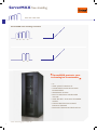
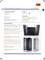
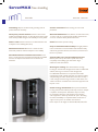
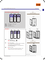
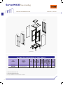
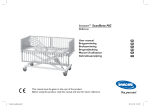
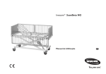
ServerMAX free standing
• Compatible with all EIA-310 compliant 19” equipment. All type of servers, brands will physically fit in ServerMAX server cabinet.
• Bottom plate has an extra perforated plate to prevent insects or mice from reaching the cables.
• Efficient passive air circulation
• Numbered U positions facilitate easy installation of rack mounted equipment.
3
ServerMAX free standing
600x1000 - 800x1000
ServerMAX free standing enclosure
26U 36U
42U
47U
42U
47U
600 x 1000*
800 x 1000*
ServerMAX protects your
technological investments
•19”
•HIGH QUALITY PRODUCTS
•COMPLIMENTS YOUR DECOR AND ENVIRONMENT
•SECURE AND STURDY
•EASY TO MAINTAIN: LARGEINNER VOLUME
•HIGH SECURITY FOR UNAUTHORIZED ACCESS
•STRONG PROTECTION AGAINST PHYSICAL DAMAGE
•EXCELLENT PASSIVE AIR VENTILATION
* Please check drawing pages for cabinet sizes.
4
SERVERMAX FREE STANDING ENCLOSURES FOR
STANDARD DIMENSIONS:
Heights: 26U, 36U, 42U, 47U
Width: 600 mm
Depth: 1000 mm
Heights: 42U, 47U
Width: 780 mm
Depth: 1000 mm
LOAD CARRYING CAPACITY: 1000 kg
600x1000 -800x1000
COLOUR:
RAL 9005 black
RAL 7035 light grey
STANDARDS:
ISO 9001 : 2008 Quality Management Systems
ISO 14001: 2004 Environmental Management System
19” mounting to IEC 297-1
EN 61587-1 mechanical structures (cabinets for electronic equipment)
Overall cabinet dimensions for IEC 297-2
KEY FEATURES
Adjustable mounting depth: 19” mounting angles
are adjustable in depth for various mounts for adjustable
depth distance, please look at drawing pages.
Bottom plate: fitted with an additional plate to
prevent insects/vermin. If necessary a filter may be
integrated to prevent dust infiltration.
Bottom plate is complete with pre-punched removable
sections: when airflow comes from the floor, these
sections can be removed to provide efficient airflow
inside the cabinet.
Reversible doors: Front and rear doors may be
detached and reversed to allow the door to open from
the rear of the cabinet.
Side doors are split in two: Front section used to
access the cabinet; additional smaller section secured
inside the cabinet. If additional ventilation is necessary it
can be demanded as vented. The main inner strip of this
panel is designed for the housing of cables and power
strips.
Numbered “U” positions facilitate easy installation
for rack mounted equipment.
Vertical mounting rails with square holes;
adjustable in depth.
5
ServerMAX free standing
600x1000 - 800x1000
Optional plexi front door: May be used instead of
vented front door. All in one: ServerMAX includes; casters, doors, ground
studs, levelling feet, roof, bottom, side panels, C-rails, tilt bars,
unloaded fan tray.
Optimized depth: 1000 mm.Today and next generation
installation of servers, for power distribution and cable
management. 1000 mm is the optimum depth for comfort
cabling, housing server and gaining space in data centers.
Fixing to floor: ServerMAX can be easily fixed to the
floor when necessary. A floor fixing kit is used for this
purpose. Please see accessories for floor fixing kit.
Efficient passive ventilation: New generation servers
and networking products need adequate ventilation to
operate efficiently. ServerMAX server cabinets provide
6
efficient passive ventilation because of its vented structure of
front and rear doors. Front and rear doors have maximum
perforation (%63) patterns for high-density cooling that meets
or exceeds server manufacturer’s ventilation requirements.
There is a fan tray on roof: Removable easily from
the top.When the maintanence of fans are required, it can be
reached directly from the top without touching any mounted
device or servers.
It is possible to attach a filter on top of the server fan unit.
Generous cable access holes are provided in the roof
and base. One on top, one on bottom holes are special ESTAP
style cable entries; sliding type with rubber edges.
FEATURES
Quick release side doors: During installation and while
conducting routine maintenance of installed equipment, it is
often advantageous to remove the side panels. Quick release
slam latches and locks on the side panels allow for quick and
easy access.
600x1000 - 800x1000
Anti-tilt bars: As standard, ServerMAX is fitted with
2 sliding type tilt bars to make the cabinet stable in weight
center. Whenever the servers are moved out, tilt bars are
drawn out to counter-balance the cabinets weight center.
Double opening rear doors improve access and
serviceability to rear of rack mounted equipment.The split
rear doors help to maximize floor space. Only 390 mm for
W=780 mm cabinets of clearance is required behind the
enclosure to allow for door swing.
D= 200 mm extention unit: If deeper equipment
is loaded into ServerMAX cabinets requiring additional
depth for cable radius, cable bundles, PDU housing etc, a
D=200mm extension unit may be installed to ServerMAX
cabinets: the rear door is removed and reinstalled onto the
extension unit. (Please see diagrams on pages 18-19)
Expansion: ServerMAX enclosures can be easily
expanded to create complete rows of enclosures without
side panels. With a proper baying kit (please see accessories)
all cabinets are bayed easily and quickly.
Welded: Bottom and roof of the cabinet is completely
welded and a closed structure. Sturdy and rugged, it protects
against physical elements like dust, insects.
Lockable doors and side panels: Front and rear
doors are lockable using a 3 point locking mechanism. A handle-style locking system provides increased security to
prevent unauthorized access. All doors and side panels are
only accessible with a key provided by ServerMAX.
Stability: Heavy duty frame design, 2 mm mounting rails,
angles, heavy duty type castor group provide 1000 kg load
rating.
7
ServerMAX free standing
FEATURES 600x1000 - 800x1000
Grounding: All parts are fitted with grounding studs to
provide electrical continuity.
Surface treatment: Fosfat coating, oil remove and
passivation.
Heavy duty vertical frames: Instead of 4ea. vertical
profiles, ServerMAX cabinets are 6ea.(3ea.in left+3ea.in right)
main vertical profiles that gives extra stability for heavy loads.
Material thicknesses: Roof, bottom, vertical main frames,
1,5 mm C-rails, 19” mounting angles, profiles and all frames
are 2 mm thickness. Sturdy steel construction.
More C rails: Instead of 6ea. there are 8 horizontal C rails
in depth for extra stability. (42U, 47U)
Paint: Electrostatic powder coating.
Reinforced bottom: Bottoms are reinforced with
horizontal profiles in width and depth for extra stability.
Rounded aesthetic monoblok front door: Front
door is a heavy duty type monoblock perforated and welded
structure. It’s shape is rounded in front to enhance the
aesthetics.
Easy to dismantle and assembly: The rigidly welded
frame construction can be dismantled and assembled easily
without any special tools.Thus, narrow doors, staircases and
lifts are no problem. Special cable entry on top and bottom case:
Bottom plate and top case have a special cable entry,
completely closed, sliding type with rubber edges.
Cables are entered and fixed.
Housing for cabling: The cabinet itself has enough
housing for vertical cable management at back. For 600x1000
cabinet, cable rings are used for cable management.
For 780x1000 cabinets there are special vertical cable
management panels of Ieft & right with cover plate for hiding
and protecting the cables. These allow customers to easily
route, manage and access large numbers of data cables even
while an enclosure is loaded with rack mount equipment and
bayed in a row.
Power/energy distribution: Rear power distribution
housing at back of the cabinet provide easy access to multiple
receptacles. Vertical power distribution strips can easily
be mounted in that space. This housing never interfere
with equipment or takes any valuable “U” space. Providing
increased accessibility to receptacles allows customers to
support more power cords within the enclosure.
Power strips are the length of cabinets: 26U, 36U, 42U, 47U.
8
ADDITIONAL FEATURES FOR More Volume Width=780 mm:
Provides more efficient
cooling and more
professional cabling
ServerMAX Width=780 mm cabinet has all
features mentioned before. Plus these additional
features.
800x1000 mm
Vertical cable management panels can be used at
rear of the cabinet for professional cabling and to hide the
power cables.
Extra Housing space for cabling and power
distribution: This extra space provides housing for the
vertical cable management panels and the vertical power
strips.
Left and right front panel: Front panels can be used to
hide unwanted views of cables. If server cabinet is additionally
used for networking in the front, cable management is needed:
Estap cable rings can be used to attach this panel and secure
cables.Access holes allow the patch cord to reach the rear of
cabinet.
9
ServerMAX free standing
SELECTION STEPS FOR
600x1000
STEPS TO SELECT THE RIGHT FREE STANDING ENCLOSURE
In addition to Estap product part numbers, the options mentioned on the next page are to supply the right
definition to meet your requirements.
Each wall mounted and free standing enclosure section in the catalogue, has a ‘’Main part number structure’’ and
‘’Options’’ sections.
The below example explains how to select the right options for your needs.
The product part number has the below structure for ServerMAX W=600 mm:
Product range name
+
U height (HHU)
The product options have the below structure:
Colour option (MX)
+
Front door option (FX)
+ Rear door option (RX)
HOW TO SELECT THE OPTIONS
Step 1
Please choose product part number.
For example : SRV42U (Width=600 mm)
Step 2
Please choose the colour from the table and place it after the part number.
For example : SRV42U - M01 (MX=Look at the MX colour options on the next page)
Step 3
Please choose the front door from the table and place it after MX colour.
For example : SRV42U - M01 - F15 (FX= look at the FX front door options on the next page)
Step 4
Please choose the rear door from the table and place it after FX front door option.
For example : SRV42U - M01 - F15 - R07 (RX= look at the RX rear door options on the next page)
10
PART NUMBER DEFINITION FOR 600x1000
FX***
MAIN PART NUMBER STRUCTURE
SRV Product
range
ServerMAX
F14**
U
height
+
SRV
Front door options
- HHU
600
HHU
26U
36U
SRV
42U
47U
H
SRV: ServerMAX product range (W=600 mm)
HHU: “U” height
WD: 600x1000 mm
Front view
F15
R07*
600
OPTIONS
MX - FX MX
- RX
Front
door
options
Colour
options
+
FX
M01
F14**
M02
F15
600
Rear
door
options
+
RX
R07*
H
H
R07*
MX:
Colour options
M01= RAL 9005 black M02= RAL 7035 light grey
Front view
Front view
RX***
Rear door option
FX: Front door options
F14**= Single opening, monoblock,welded, curved %63 perforated door, 3 point handled locking F15= Single opening, monoblock,welded, curved plexi glass door, 3 point handled locking
R07*
600
RX: Rear door option
q R07*= Double opening %63 perforated door with complete metal frame, 3 point handled locking
H
Back view
H= Enclosure height
* R07 is the standard rear door.
** F14 is the standard front door.
*** F14, F15 R07 can be used as front or rear door.
11
ServerMAX free standing
TECHNICAL DRAWINGS FOR 600x1000 - 26U/36U/42U/47U
R07* / ***
F14** / ***
F15***
Exploded view
Part
number
Product
definition
(mm)
U
Size
Width:
overall
(mm)
Depth:
overall
(mm)
Depth: max
mounting
profile (mm)
Height:
vertical
mounting
profile (mm)
Height:
without
levelling feet
(mm)
Height:
with casters
(mm)
ServerMAX cabinets 19” 600 x 1000 mm
SRV26U
26U 600x1000 mm
26
600
1000
740
1179
1291
1338
SRV36U
36U 600x1000 mm
36
600
1000
740
1623
1735
1782
SRV42U
42U 600x1000 mm
42
600
1000
740
1890
2002
2049
SRV47U
47U 600x1000 mm
47
600
1000
740
2112
2224
2271
* R07 is the standard rear door.
** F14 is the standard front door.
*** F14, F15, R07 can be used as front or rear door.
12
TECHNICAL DRAWINGS FOR
600x1000 - 26U/36U/42U/47U
565
200
180
(Min 795)
740
H
Front view
Bottom view
Mounting profile
1000
12
600
F14**
(Min 25)
56
140
140
906
200
(Min 158)
184
600
600
F15
H
Front view
47
H
Side view
Back view
Front view
600
200
R07*
1000
200
600
30
H
Top view
H= Enclosure height
Iso view
Front view
*R07 is the standard rear door.
** F14 is the standard front door.
13
ServerMAX free standing
PART NUMBER DEFINITION FOR
800x1000
STEPS TO SELECT THE RIGHT FREE STANDING ENCLOSURE
In addition to Estap product part numbers, the options mentioned on the next page are to supply the right
definition to meet your requirements.
Each wall mounted and free standing enclosure section in the catalogue, has a ‘’Main part number structure’’ and
‘’Options’’ sections.
The below example explains how to select the right options for your needs.
The product part number has the below structure for ServerMAX W=780 mm:
Product range name
+
U height (HHU)
+ Width (WW, D=1000 mm)
The product options have the below structure:
Colour option (MX)
+
Front door option (FX)
+
Rear door option (RX)
HOW TO SELECT THE OPTIONS
Step 1
Please choose product part number.
For example : SRV42U8 (Width=780 mm)
Step 2
Please choose the colour from the table and place it after the part number.
For example: SRV42U8 - M01 (MX= Look at the MX colour options on the next page)
Step 3
Please choose the front door from the table and place it after MX colour.
For example: SRV42U8 - M01 - F16 (FX= Look at the FX front door options on the next page)
Step 4
Please choose the rear door from the table and place it after FX front door option.
For example: SRV42U8 - M01 - F16 - R08 (RX= Look at the RX rear door options on the next page)
14
PART NUMBER DEFINITION FOR
800x1000
FX***
MAIN PART NUMBER STRUCTURE
Front door options
SRV - HHU - WW
Product
range
ServerMAX
SRV
Width
&
depth=
1000 mm
U
height
+
HHU
+
780
8
42U
SRV
F16**
WW
47U
H
SRV: ServerMAX product range HHU: “U” height
WW: Width (W=780 mm)
OPTIONS
MX - FX
- RX
Front
door
options
Colour
options
MX
Front view
+
FX
M01
F16**
M02
F17
F17
R08*
780
780
Rear
door
options
+
RX
R08*
H
H
R08*
MX: Colour options
M01= RAL 9005 black
M02= RAL 7035 light grey
Front view
Front view
RX***
Rear door option
FX: Front door options
F16**= Single opening, monoblock, welded, curved %63 perforated door, 3 point handled locking
F17= Single opening, welded, curved plexi glass door,
3 point handled locking
R08*
780
RX: Rear door option
R08*= Double opening %63 perforated door with complete metal frame, 3 point handled locking
H
Back view
H= Enclosure height
* R08 is the standard rear door.
** F16 is the standard front door.
*** F16, F17 R08 can be used as front or rear door.
15
ServerMAX free standing
TECHNICAL DRAWINGS FOR
800x1000 - 42U/47U
R08*/***
F16**/***
F17***
Exploded view
Part
number
Product
definition
(mm)
U
Size
Width:
overall
(mm)
Depth:
overall
(mm)
Depth: max
mounting
profile (mm)
Height:
vertical
mounting
profile (mm)
Height:
without
levelling feet
(mm)
Height:
with casters
(mm)
ServerMAX free standing cabinets 19” 780 x 1000 mm
SRV42U8
42U 780x1000 mm
42
780
1000
740
1890
2002
2049
SRV47U8
47U 780x1000 mm
47
780
1000
740
2112
2224
2271
* R08 is the standard rear door.
** F16 is the standard front door.
*** F16, F17, R08 can be used as front or rear door.
16
TECHNICAL DRAWINGS FOR
800x1000 - 42U/47U
780
745
F16**
(Min 762)
740
H
(Min 27)
44
140
140
906
200
(Min 190)
195
300
280
19”
Mounting profile
Bottom view
1000
780
12
780
Front view
H
H
Side view
47
Front view
F17
Back view
Front view
780
780
R08*
200
300
Top view
H= Enclosure height
29
1000
H
Iso view
Front view
* R08 is the standard rear door.
** F16 is the standard front door.
17
ServerMAX free standing
TECHNICAL DRAWINGS FOR
600x1000
Technical drawing of extention unit D=200 mm for 600x1000 mm ServerMAX
Top view after extention unit
600
70
200
145
Note: Depth of existing cabinet + 200 mm
Exploded view
Iso view
18
Part
number
Product definition
(mm)
U
Size
Width:
overall
(mm)
Depth:
overall
(mm)
Height:
without
levelling feet
(mm)
Height:
with casters
(mm)
ServerMAX 19” 600 x 1000 mm extention unit
SRV26U EXT620
26U Extention unit D=200 mm, suitable for ServerMAX W=600 mm
26
600
200
1281
1328
SRV36U EXT620
36U Extention unit D=200 mm, suitable for ServerMAX W=600 mm
36
600
200
1726
1773
SRV42U EXT620
42U Extention unit D=200 mm, suitable for ServerMAX W=600 mm
42
600
200
1993
2040
SRV47U EXT620
47U Extention unit D=200 mm, suitable for ServerMAX W=600 mm
47
600
200
2215
2262
TECHNICAL DRAWINGS FOR 800x1000
Technical drawing of extention unit D=200 mm for 780x1000 mm ServerMAX
Top view after extention unit
780
70
200
145
Note: Depth of existing cabinet + 200 mm
Exploded view
Iso view
Part
number
Product definition
(mm)
U
Size
Width:
overall
(mm)
Depth:
overall
(mm)
Height:
without
levelling feet
(mm)
Height:
with casters
(mm)
ServerMAX 19” 780 x 1000 mm extention unit
SRV42U EXT820
42U Extention unit D=200 mm, suitable for ServerMAX W=780 mm
42
780
200
1993
2040
SRV47U EXT820
47U Extention unit D=200 mm, suitable for ServerMAX W=780 mm
47
780
200
2215
2262
19
ServerMAX free standing
TECHNICAL SPECIFICATIONS
TESTS AND CERTIFICATIONS
Environment EN61587-1/4.2, IEC60068-2-1, IEC60068-2-2, IEC60068-2-30, IEC60917 and IEC60297
Industrial environment EN61587-1/4.3, IEC60068-2-42, IEC60068-2-43 and
IEC60068-2-49,IEC60068-2-1, IEC60917 and IEC60297
Statical mechanical structure load test EN61587-1 / 5.2.1, IEC60917 and IEC60297
Statical mechanical structure stability EN61587-1 / 5.2.2, IEC60917 and IEC60297
Dynamic load, vibration and mechanical stroke
EN61587-1 / 5.3.1, EN61587-1 / 5.3.3, IEC60917, IEC60297, IEC62208
Grounding continuity
EN61587-1 / 6.2, IEC60917 and IEC60297
Fire and flame resistance
EN61587-1 / 6.3, IEC60917 and IEC60297
Corrosion
ISO9227 and ASTM B 117-85, IEC60917 and IEC60297
IP protection degree IP20 accordingly EN61587-1 / 6.4, IEC60529, IEC60917 and
IEC60297
Transportation
ETS300019-1-2 Class 2.3
Storage
ETS300019-1-1 Class 1.2
Security
EN60950_LVD
PURCHASED PRODUCT CERTIFICATIONS
Sheet steel
DIN EN 10130 – 99 Ereğli DC- 01 6112, 7122, RoHS
Electrostatic powder coating
ISO 9001, ISO 2178, ISO 2813, ISO 6272, ISO 8130-5,
ISO 8130-3, RoHS
Fan
ISO 9001, CE (89/336/EEC EMC, 73/23/EEC LVD), RoHS
Glass
ISO 9001, EN 12150 – 1: 2000 tempered and secure
Fixings
DIN 7985, DIN 965, DIN 7981, DIN 934, DIN 985, DIN 933,
RoHS
Castors
TS EN 12530, TS EN 12532, RoHS
Lock
DIN 1743, DIN 53571, RoHS
20
KEY FEATURES
Main profile (framework) has an aesthetic structure which
increases mechanical resistance, folded at an angle of 90
degrees and consisting of 4 bends for each profile. In total;
16 folds provide framework stability.Additionally, 2 piece
vertical side panel divider profile provides additional
resistance each with a 4 fold design; total of 8 fold additional
support. In total ServerMax main profile framework consists
of a 24 fold engineering design. Manufactured and tested to
provide axial (x, y, z) resistance that meets EN 61587-1 / 5.2.1
and 5.2.2, and external impact resistance that meets
EN 61587-1 / 5.3.3. Bottom and upper cases have a structure to increase
the resistance and strength of the cabinet by monoblock
bended, welded and profile-interlocking design. Profiles are
manufactured to interlock bottom and upper cases with
screws. The bottom case providing cable access is fitted with
a sliding blanking access plate to prevent dust.
A rubber edge on the cable access plate and sliding structure,
it is possible to fix the cables and allows cables to be placed
into the cabinet without any damage.
Additional there are pre-punched knock outs for air
distribution delivered from raised floor. Rear door in standard configuration is a double opening
door which is removable and lockable. Integral locking is a 3
point locking system.
Rear doors can be opened up to 215 degrees, are removable
and lockable with handle type locking unit.
Side panels have a structure that can be opened and
removed with slam latch and key.They are lockable and
removable. Side panels consist of a divider profile which
creates 2 pieces side panels on each side. Original functional
side panel is lockable and removable as mentioned above;
the smaller side panel is fixed from inner side with screws.
If additional ventilation is needed this panel can be replaced
with a slotted / perforated one.
Within this engineering construction, the original functional
side panel becomes easy to carry while the divider profile
provides better resistancy.
Front doors are single opening, monoblock, welded, curved,
%63 perforated in standard. Integral locking as 3 point locking
system. For options please see the related diagrams and
technical charts in pages 11-15.
Front door can be opened up to 215 degrees, removable and
lockable with handle type locking unit.
Vented top panel housing with a dedicated space for
ventilation, the fan module system allows easy installation of
max. 6 fans from top.
19”(inch) mounting angles (2ea. in front and 2ea. in rear) are
part of cabinet interior configuration and adjustable in depth.
Baying is possible for side by side applications without
side panels. Levelling feet and integrated castor group are
standard in shipping configuration.
The cabinet meets EN 61587-1, IEC 60917, IEC 60297
standards, RoHS compliancy, Gost and TSE certified.
Cabinets are manufactured in our factory which has
ISO 9001: 2008 Quality Assurance System and our
responsibility for enviroment with ISO 14001:2004
Environmental Management System.
TECHNICAL SPECIFICATIONS
Custom number
85380000 / 85381000 / 853710990019
Packs of (ea.)
1
Shipping structure
Assembled
Mounting surface
Stand alone
Load carrying capacity (kg)
1000
Certification on product
TSE, Gost
Surface finish
Electrostatic powder coated c/with surface treatment , 80 +/ - 5
micron paint thickness and tested according to IEC 60068-21,2-2, 2-30,2-42, 2-43, 2-49, 2-11
STANDARD PRODUCT
Standart colour
RAL 7035, RAL 9005
Baying
Possible with baying kit for side by side applications without side
panels IP protection standard
IP20
FRONT DOOR
Single opening, monoblock, welded,curved, %63 perforated
Front door construction
Monoblock curved, welded construction
Front door lock
Handle type, 3 point locking
Hinge system
Spring loaded
Door opening angle and swapping
215 degree
Door opening angle and swapping
215 degree
FRAMEWORK Top and bottom base units
Solid Metal 2 mm
Top and bottom base units construction
Completely welded corner socket system
Uprights
Solid metal, 2 mm
Uprights construction
Tightly fixed into top and bottom base units
3 times folded 3 x 2 = 6 folds
SIDE PANEL DIVIDER PROFILE
Solid metal 2 mm
Side panel construction
Tightly fixed into top and bottom base units
4 times folded x 2 = 8 folds
INTERIOR PARTS 19’’ mounting angles
Solid metal, 2 mm
1 times folded for an L profile system
U marking available
2 ea. at rear, 2 ea. at front
Pre-configured as 19’’
Zinc plated, passivated, 8-12 micron
Adjustable in depth
Omega type support rails in depth
Solid metal, 1,5 mm
3 times folded for W=600 mm cabinets
Omega type folded for W=780 mm cabinets
3 ea. at left, 3 ea. at right 26U and 36U
4 ea. at left, 4 ea. at right 42U and 47U
SIDE PANEL
Solid metal, 1 mm. Left and right (2ea.)
Construction
Lockable, removable c/with slam latches and lock
Lock
Barrel type lock unit, single point + slam latch (2ea)
REAR DOOR
Solid metal, 1 mm
Rear door construction
Double door opening, %63 perforated, lockable, removable
Rear door lock
Handled type lock unit, 3 point
Hinge system
Spring loaded
For CUSTOMIZED PRODUCTS rather than
above options, please contact sales department. 21
ServerMAX free standing accessories
FREQUENTLY USED ACCESSORIES SELECTION CHART FOR SERVERMAX
Estap has a wide range of accessories: Heavy duty fixed shelves, sliding shelves, fans, cooling units, vertical cable
managements, cable rings, organisers, trays, plinths and so on...
* See the other and part number definition on pages 173-213.
* Please state colour choice in your orders. M01=RAL 9005 black and M02= RAL 7035 light grey
Frequently used accessories selection table
ServerMAX / Vertical PDU part numbers
M44 24 AL IEC AMP MCB
ServerMAX / Cable management unit
(suitable for 780x1000 Server Cabinets)
Enclosure sizes*
800x1000
42U
M44ORG42SRV
47U
M44ORG47SRV
ServerMAX /
Cable management rings
Part number
44x30
K44RING01
44x60
K44RING021U
44x110
K44RING03
70x160
K44RING04
ServerMAX /
Floor fixing kit
Enclosure sizes*
600x1000
800x1000
M44DPR03
22
* Please check drawing pages for cabinet sizes.
M44DPR04