1
OQ
RAID
A
ID
M
A
X
т"
U
S
E
R
S
MAN
U
A
L
Letter to User
Dear Yalved Customers,
On behalf of EAIDMAX Team, thank you for purchasing our product. With the booming of the gaming
market and computer cases, EAIDMAX would like to differentiate ourselves from other case companies
by continuously providing high quality and innovative next generation cases. If you have any critiques or
comments, please feel free to forward us an email. After all, we are designing the cases for you. Thank you
again for purchasing our RAIDMAX case. We hope fo serve you again in near future,
Sincerely,
RAIDMAX GENERAL MANAGER
Eric: Lin
Power Supply Installation
Please refer to the case interior infrastructure and secure the power supply at the back of the case by using
the screws provided. NOTE: CPU, RAM and any peripheral installation are not included in this manual,
Please refer to your motherboard manual for related mounting instructions and troubleshooting.
Motherboard Installation
Your RAIDMAX case supports the following motherboard: ATX, BABY AT, MINI ATX, and MICRO ATX, The Index
for the standoff holes are as follows. (Imprinted on the motherboard tray are serial numbers that match
certain motherboards)
Al=-AT ATX
81-87 BABY AT
M1 =M2 MINI ATX
UT=U7 MICRO ATX
In order to install your motherboard go through the following steps:
1. Lay your case down 50 you con see the drive cages and the standoff holes on the motherboard fray.
2. Take your motherboard and match the standoff holes.
3. Remembering which standoff holes your motherboard needs, go ahead and screw the brass standoffs
onto the motherboard tray. (Note: If you find that some holes are unused, this is normal, this case is made to
support for many motherboard sizes)
4, Place your motherboard on top of the brass standoffs and attach it to the tray by using screws provided.
5. Connect the 20- pin ATX power connector from your power supply (and AUX or +12V connectors if
appropriate) to your motherboard.
Front Panel Wiring Installation
Tour front panel has several wire connections that need to be installed. This section provides you with a
brief description of each wire and how to install them.
Front panel leads
Inside the case there are several leads that need to be plugged in; power switch lead, power LED lead,
reset switch lead, and hard drive status lead,
1. Power LED leodlpcwer te LE "seat"
The blue vvire E +12 dnd the while wire is ground.
This wire: plugs info any ATX 4 pin molex connector from the power supply.
2, Power switch lead power switch Pug)
The orange wire 5 a positive [+) charge and the white wire i a negative|-] charge
This wire plugs into the motherboard wheng all the front panel switch/pn connéclors funclions are located.
The motherboard manual will have a conce descripiton of where to plug this in, usualy in the motherboard
manual the location is labeled “POWER ON BUTTON or POWER SW".
3. Reset switch lead mes swich pug)
The Blue wire is @ + charge and the white wire i a - charge
This wire plugs info the motherboard where all tha front panel switch/pin connectors functions ore located.
Thr motherboard manual will have a concise dascripiton of where to plug this in. usually in the motherboard
manual the location & labeled “RESET BUTTON or RESET SW",
4. Hard drive LED status lead named when hard drive is In ue)
The red wire is a positive +) charge and the white wire в а negative(-) charge
This wire plugs info the motherboard where all the front panel switch/pin connectors funchions ore located.
Tree motherboard manual will have a concise description of where 1o plug this in, usually in the molherboand
manual the location E lobeled “Hard drive LED or HDD LED".
USB port installation
This section tells you how to connect the USB ports at the front of the case,
—
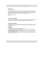
. USB 2.0 Cable Description
Inside your cose are 2 USE 2.0 cables. These cable are labeled on the black leads, Each cable has
a 4 pin lead and oa single lead. The 4 pin lead hos the following connections; USE +54, USE_P1-,
LUSB_P1+, and GND, The single |éad is à conneclor lobéled =MC”,
11 2. USB 2.0 Cable Installation
Fired thé “USE Headers/Pin Connection” on the motherboard,
Plug in the wires according to the motherboard manual,
Ceagram 1.1 is a general diagram and may nol resemble your specific motherboard.
MOTE: If you have and extra single legd labeled NC, and there i no pin foril, legve il deconnected
Audio port installation
This section tells you how to connect the headphone and microphone jack at the front of the case.
1. Audio Port Cable Description
Inside your casé is o ingle ended audio cable that connects 2 cables togathear. This B your front
audio porf connector, This wire hos 7 single lego connector labeled as the following: LIME-QUT-R,
BLIME-SUT-R, LINE-CUT-L. BLIME-CUT-1, ABC Pee, MICT. & AGND
mCI——aco 14 (2. Audio Port Cable Instalafion
e + e qua | Find the “Front Panel Audio Headers/Pin connecters”
— —"1 Plug in the wires according to the motherboard manual.
LIE Ur. 0 — BUNE_OUT_L Diagram 1.2 is a general diagram and may nol resemble your specific matherboord.
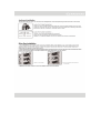
Drive Bay Installation
1. Your RAIDMAX case comes with a lock on screwless drive cage design 50 you can easily pull out and
replace drives. For the 5.25" devices, match the screw hole of your drive with the drive bay holder and
make sure the device is where you want it.
2. Lock and secure the drive in by pushing the lock towards the front of the case and then pushing the other
button downwards. Refer to the figure below for more explanation on the motion.
2. push towards the bottom
to secure
l.push to the nght
3. Repeat the some motion for your 3.57 floppy drives and hard drives.
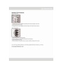
Using the Card fasteners
Type 1 Instructions
1. Squeeze the hwo tabs together and pull oway from the inside of the case
Z Insert PCIE/AGP/PCI Card
à Squeeze the two tabs together and push back until card is firmly in place
Type 2 Instructions
1. Press notated tab in type 2 picture
2. Flip the fastener to the left (this will open the slot space)
4. Insert PCIE/AGP/PCI Card
4. Flip the fastener to the right until you hear a click{this will secure the card)
If you have any further questions or comments, please feel free to forward us an e-mail;
[email protected].
<>
EAEMAX™
WWW. RAIDMAX.CDOM