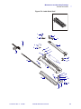
1
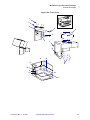
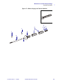
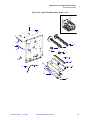
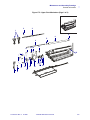
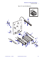
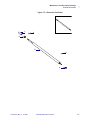
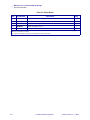
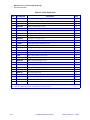
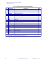
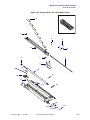
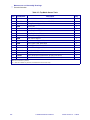
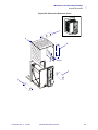
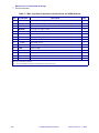
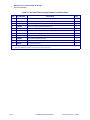
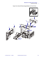
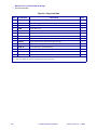
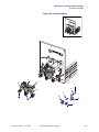
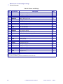
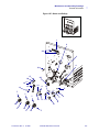
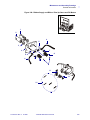
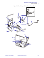
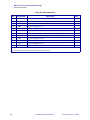
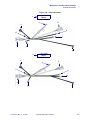
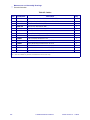
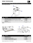
5
Maintenance and Assembly
Drawings
This section contains mechanical assembly drawings and parts lists. Included are illustrations
of parts and assemblies common to all 170PAX4 models, as well as their part numbers.
Maintenance kits and their contents are also listed.
Contents
Front Cover . . . . . . . . . . . . . . . . . . . . . . . . . . . . . . . . . . . . . . . . . . . . . . . . . . . . . . . . . .
Door-Open Switch . . . . . . . . . . . . . . . . . . . . . . . . . . . . . . . . . . . . . . . . . . . . . . . . . . . . .
Ribbon Supply and Take-Up Spindles . . . . . . . . . . . . . . . . . . . . . . . . . . . . . . . . . . . . . .
Spindle Gear Cover . . . . . . . . . . . . . . . . . . . . . . . . . . . . . . . . . . . . . . . . . . . . . . . . . . . .
Printhead . . . . . . . . . . . . . . . . . . . . . . . . . . . . . . . . . . . . . . . . . . . . . . . . . . . . . . . . . . . .
Upper Print Mechanism (Page 1 of 2) . . . . . . . . . . . . . . . . . . . . . . . . . . . . . . . . . . . . . .
Upper Print Mechanism (Page 2 of 2) . . . . . . . . . . . . . . . . . . . . . . . . . . . . . . . . . . . . . .
Lower Print Mechanism . . . . . . . . . . . . . . . . . . . . . . . . . . . . . . . . . . . . . . . . . . . . . . . . .
Elastomer Peel Roller . . . . . . . . . . . . . . . . . . . . . . . . . . . . . . . . . . . . . . . . . . . . . . . . . .
Platen Roller. . . . . . . . . . . . . . . . . . . . . . . . . . . . . . . . . . . . . . . . . . . . . . . . . . . . . . . . . .
Label Guide Shelf. . . . . . . . . . . . . . . . . . . . . . . . . . . . . . . . . . . . . . . . . . . . . . . . . . . . . .
Segment Roller and Lower Media Sensor . . . . . . . . . . . . . . . . . . . . . . . . . . . . . . . . . . .
Top Media Sensor Track . . . . . . . . . . . . . . . . . . . . . . . . . . . . . . . . . . . . . . . . . . . . . . . .
Electronics Enclosure Cover . . . . . . . . . . . . . . . . . . . . . . . . . . . . . . . . . . . . . . . . . . . . .
Main Logic Board, Applicator Interface Board, and PCMCIA Board . . . . . . . . . . . . . . .
AC and DC Power Supply Boards and Control Panel . . . . . . . . . . . . . . . . . . . . . . . . . .
Pulleys and Belts . . . . . . . . . . . . . . . . . . . . . . . . . . . . . . . . . . . . . . . . . . . . . . . . . . . . . .
Intermediate Pulley and Stepper Motor . . . . . . . . . . . . . . . . . . . . . . . . . . . . . . . . . . . . .
Gears and Pulleys . . . . . . . . . . . . . . . . . . . . . . . . . . . . . . . . . . . . . . . . . . . . . . . . . . . . .
Ribbon Supply and Ribbon Take-Up Gears and DC Motors . . . . . . . . . . . . . . . . . . . . .
Power Entry and Ribbon Tension Control Board . . . . . . . . . . . . . . . . . . . . . . . . . . . . . .
Cable Harnesses . . . . . . . . . . . . . . . . . . . . . . . . . . . . . . . . . . . . . . . . . . . . . . . . . . . . . .
Cables . . . . . . . . . . . . . . . . . . . . . . . . . . . . . . . . . . . . . . . . . . . . . . . . . . . . . . . . . . . . . .
57518L-001 Rev. A 3/18/05
170PAX4 Maintenance Manual
300
302
304
306
308
310
312
314
316
318
320
322
324
326
328
330
252
334
336
258
340
342
344
297
Maintenance and Assembly Drawings
Notes • ___________________________________________________________________
__________________________________________________________________________
__________________________________________________________________________
__________________________________________________________________________
__________________________________________________________________________
__________________________________________________________________________
__________________________________________________________________________
__________________________________________________________________________
__________________________________________________________________________
__________________________________________________________________________
298
170PAX4 Maintenance Manual
57518L-001 Rev. A 3/18/05
Maintenance and Assembly Drawings
General Information
General Information
This section identifies parts and assemblies in the 170PAX4 print engine using parts tables and
figures. Both assemblies and parts are listed in the table, and the individual parts are identified
in the associated figure.
In each of the tables, parts shown in bold face can be purchased. Parts shown italicized are not
purchasable, but may be available as a maintenance kit. (This information appears in the key at
the bottom of each parts table.)
Hardware items with an “HW” preceding the part number are not available as individual parts.
You can purchase an item as part of a hardware kit in quantities listed in the parts table.
The parts tables list part numbers for both right-hand (RH) and left-hand (LH) print engines.
All graphics shown in this section are for the right-hand 170PAX4 print engine only.
57518L-001 Rev. A 3/18/05
170PAX4 Maintenance Manual
299
Maintenance and Assembly Drawings
General Information
Table 23 • Front Cover
Item
Part Number
Description
Qty.
1
HW43676
Screw, Pan Head M5 × 0.8 (Qty. of 25)
8
2
49244M
Door Hinge Maintenance Kit
2
3
49687
Ground Strap
1
4
HW10477
Washer, Split (Qty. of 10)
10
5
HW44055
Nut, Hex M5 (Qty. of 25)
10
6
57377
Shroud, Rear (RH)
1
6
57378
Shroud, Rear (LH)
1
7
57379
Shroud, Front (RH)
1
7
57380
Shroud, Front (LH)
1
Label, Zebra Logo 170PAX4
1
8
57502
9
HW06262
Nut, Hex 6-32 (Qty. of 25)
4
10
HW01159
Washer, Lock External #6 (Qty. of 100)
4
11
49028
Shroud, Window
1
Bold = Part available for purchase
Italic = Part not available for purchase, listed and shown for reference only
300
170PAX4 Maintenance Manual
57518L-001 Rev. A 3/18/05
Maintenance and Assembly Drawings
General Information
Figure 169 • Front Cover
2
1
2
3
6
2
4
5
7
8
9
9
9
2
10
9
10
10
11
57518L-001 Rev. A 3/18/05
170PAX4 Maintenance Manual
301
Maintenance and Assembly Drawings
General Information
Table 24 • Door-Open Switch
Item
Part Number
Description
Qty.
1
49865
Label, Media Load (RH)
1
1
49928
Label, Media Load (LH)
1
2
HW10431
Screw, Cap M4 × 0.7 (Qty. of 25)
4
3
HW44192
Screw, Pan Head 2-56, 0.50 (Qty. of 25)
2
4
49858
Bar, Nut
1
5
57355M
Door-Open Switch Maintenance Kit
1
Bold = Part available for purchase
Italic = Part not available for purchase, listed and shown for reference only
302
170PAX4 Maintenance Manual
57518L-001 Rev. A 3/18/05
Maintenance and Assembly Drawings
General Information
Figure 170 • Door-Open Switch
MEDIA
AND R
IBB
1
3
2
5
4
2
2
57518L-001 Rev. A 3/18/05
170PAX4 Maintenance Manual
303
Maintenance and Assembly Drawings
General Information
Table 25 • Ribbon Supply and Take-Up Spindles
Item
Part Number
Description
Qty.
1
HW10188
E-Ring (Qty. of 5)
2
2
49084
Shaft, Spindle
1
3
HW30114
Washer, Flat (Qty. of 25)
1*
4
49319M
Ribbon Take-Up Gear Maintenance Kit
1
4
49394M
Ribbon Supply Gear Maintenance Kit
1
5
49379
Spindle, Outer Ribbon
2
6
HW49441
Washer (Qty. of 50)
1*
7
HW49445
Washer (Qty. of 50)
1*
Bold = Part available for purchase
Italic = Part not available for purchase, listed and shown for reference only
* = As required to achieve 0.010 end play
304
170PAX4 Maintenance Manual
57518L-001 Rev. A 3/18/05
Maintenance and Assembly Drawings
General Information
Figure 171 • Ribbon Supply and Take-Up Spindles
6
5
1
1
3
7
4
2
3
57518L-001 Rev. A 3/18/05
170PAX4 Maintenance Manual
305
Maintenance and Assembly Drawings
General Information
Table 26 • Spindle Gear Cover
Item
Part Number
Description
Qty.
1
49088
Cover, Spindle Gear (RH)
1
1
49488
Cover, Spindle Gear (LH)
1
2
HW10413
Screw, Cap M3 × 0.5 (Qty. of 50)
3
Bold = Part available for purchase
Italic = Part not available for purchase, listed and shown for reference only
306
170PAX4 Maintenance Manual
57518L-001 Rev. A 3/18/05
Maintenance and Assembly Drawings
General Information
Figure 172 • Spindle Gear Cover
1
2
57518L-001 Rev. A 3/18/05
170PAX4 Maintenance Manual
307
Maintenance and Assembly Drawings
General Information
Table 27 • Printhead
Item
Part Number
Description
Qty.
1
HW10413
Screw, Cap M3 × 0.5 (Qty. of 50)
8
2
30781
Cable, Printhead Ground
1
3
HW01159
Washer, Lock External, #6 (Qty. of 100)
1
4
HW48182
Rivet, Snap (Qty. of 10)
2
5
57493
Plate, Pressure (RH)
1
5
57494
Plate, Pressure (LH)
1
6
57376
Pad, Pressure
7
49226
Screw, Head Adjustment, M3
2
8
HW10471
Washer, Split M3 (Qty. of 50)
4
9
49164
Plate, Washer
1
10
HW30402-006 Screw, 6-32 (Qty. of 25)
2
11
57490
Bracket, Head Mounting (RH)
1
11
57491
Bracket, Head Mounting (LH)
1
12
22016
Screw, M3 × 0.5
1
13
49216
Plate, Strip
1
14
HW10401
Screw, M3 × 0.5 (Qty. of 50)
2
15
30007-7
Shaft, Roller
1
16
48099-7
Roller
1
17
49064
Bar, Adjustment
2
18
49032
Bar, Head Pivot
1
19
Q06020
Tie, Cable
2
20
57423M
Cable, Printhead Power
1
21
57360
Cable, Printhead Data
1
22
38000M
Printhead Maintenance Kit (203 dpi)
1
22
46500M
Printhead Maintenance Kit (300 dpi)
1
22
49494M
Printhead Conversion Maintenance Kit (203 to 300 dpi)
1
22
49497M
Printhead Conversion Maintenance Kit (300 to 203 dpi)
1
Bold = Part available for purchase
Italic = Part not available for purchase, listed and shown for reference only
308
170PAX4 Maintenance Manual
57518L-001 Rev. A 3/18/05
Maintenance and Assembly Drawings
General Information
Figure 173 • Printhead
1
2
3
1
4
5
7
6
1
10
8
15
9
11
10
13
14
12
14
1
17
19
20
16
22
18
57518L-001 Rev. A 3/18/05
21
170PAX4 Maintenance Manual
309
Maintenance and Assembly Drawings
General Information
Table 28 • Upper Print Mechanism (Page 1 of 2)
Item
Part Number
Description
Qty.
1
49225
Nut, M6
2
2
49191
Washer, Split M6
2
3
HW30466
Washer (Qty. of 25)
2
4
HW49152
Screw, Hex M3 × 0.6 (Qty. of 25)
4
5
49319M
Ribbon Take-Up Assembly Maintenance Kit
1
6
49394M
Ribbon Supply Assembly Maintenance Kit
1
7
49242
Plug, Recessed Head Button
2
8
HW44924
Screw, M3 × 0.5 × 8 (Qty. of 25)
3
9
43705-1M
Static Brush Maintenance Kit
1
10
57492
Extrusion, Main
1
11
49279M
Lower Ribbon Guide Maintenance Kit
1
12
46665M
Ribbon Sensor Maintenance Kit
1
13
HW44053
Screw, M3 × 0.6 × 10 (Qty. of 10)
2
14
HW49292
Spacer, Compliant Spring (Qty. of 5)
2
Bold = Part available for purchase
Italic = Part not available for purchase, listed and shown for reference only
310
170PAX4 Maintenance Manual
57518L-001 Rev. A 3/18/05
Maintenance and Assembly Drawings
General Information
Figure 174 • Upper Print Mechanism (Page 1 of 2)
4
1
3
2
5
1
2
7
3
8
6
7
8
4
9
8
12
13
10
11
14
13
57518L-001 Rev. A 3/18/05
170PAX4 Maintenance Manual
311
Maintenance and Assembly Drawings
General Information
Table 29 • Upper Print Mechanism (Page 2 of 2)
Item
Part Number
Description
Qty.
1
49099M
Printhead Pressure Maintenance Kit
2
2
HW02252
Ring, External Crescent, 0.250 (Qty. of 100)
2
3
46202
Bar, Toggle Pivot
1
4
49211
Shaft, Upper Ribbon Roller
1
5
49215
Bearing, Ribbon Guide Roller
2
6
49213
Roller, Ribbon Guide
1
7
49221M
Locking Lever Maintenance Kit (RH)
1
7
49433M
Locking Lever Maintenance Kit (LH)
1
8
HW10413
Screw, Cap M3 × 0.5 (Qty. of 50)
1
9
HW44001
Screw, Hex, M3 × 0.5 (Qty. of 25)
5
10
HW46166
Spring, Compression (Qty. of 25)
1
11
HW10856
Screw, Set M4 × 0.7 (Qty. of 25)
2
12
57381
Hub, Adjusting (RH)
1
12
57384
Hub, Adjusting (LH)
1
13
49200
Plate, Clamp
1
14
49220
Bearing, Adjustment Hub
1
15
HW49186
Screw, M2 × 0.45 (Qty. of 25)
1
16
HW10471
Washer, Split M3 (Qty. of 50)
1
17
HW30105
Bearing, Nylon (Qty. of 25)
1
18
57495
Plate, Extrusion Cover
1
19
HW49223
Washer, Adjustment Hub (Qty. of 5)
2
20
HW49227
Washer, Adjustment Hub Wave (Qty. of 5)
1
21
HW49228
Ring, External Retaining (Qty. of 25)
1
22
49168
Bearing, Flanged
1
Bold = Part available for purchase
Italic = Part not available for purchase, listed and shown for reference only
312
170PAX4 Maintenance Manual
57518L-001 Rev. A 3/18/05
Maintenance and Assembly Drawings
General Information
Figure 175 • Upper Print Mechanism (Page 2 of 2)
3
2
1
5
6
5
4
11
15 16
17
22
19 19
14
9
7
8
10
13
18
20 21
12
57518L-001 Rev. A 3/18/05
170PAX4 Maintenance Manual
313
Maintenance and Assembly Drawings
General Information
Table 30 • Lower Print Mechanism
Item
Part Number
Description
Qty.
1
HW49180
Screw, M4 × 0.7 (Qty. of 10)
3
2
HW10474
Washer, Split M4 (Qty. of 25)
3
3
HW10413
Screw, Cap M3 × 0.5 (Qty. of 50)
9
4
HW49262
Screw M3 × 0.5 (Qty. of 25)
1
5
HW11427
Screw M4 × 0.7 (Qty. of 25)
2
6
49839
Guide Post
2
7
HW01152
Washer, Flat (Qty. of 100)
2
8
57568
Label Guide Shelf Assembly
1
9
49919M
Peel Roller Maintenance Kit
1
10
HW10432
Screw M4 × 0.7 (Qty. of 25)
1
11
HW10474
Washer, Split M4 (Qty. of 25)
1
12
49931
Platen Roller
1
13
49037
Post, Lock
1
14
49826
Plate, Platen Support
1
15
57357M
Lower Media Sensor Maintenance Kit (RH)
1
15
57359M
Lower Media Sensor Maintenance Kit (LH)
1
16
49004M
Platen Support Maintenance Kit
1
17
49962
Elastomer Peel Roller
1
18
49173
Bar, Peel
1
19
HW49262
Screw M3 × 0.5 (Qty. of 10)
2
20
49224
Plate, Peel Bar Mounting (RH)
1
20
49419
Plate, Peel Bar Mounting (LH)
1
21
49833
Latch, Peel Roller (RH)
1
21
49834
Latch, Peel Roller (LH)
1
22
49836
Spring, Tension Latch (RH)
1
22
49835
Spring, Tension Latch (LH)
1
23
HW10401
Screw, M3 × 0.5 4 Pn Ph Blk (Qty. of 50)
1
24
49821
Bracket, Deflector
1
25
49056
Screw, Lead
1
26
57651M
Upper Media Sensor Maintenance Kit (RH)
1
26
57681M
Upper Media Sensor Maintenance Kit (LH)
1
Bold = Part available for purchase
Italic = Part not available for purchase, listed and shown for reference only
314
170PAX4 Maintenance Manual
57518L-001 Rev. A 3/18/05
Maintenance and Assembly Drawings
General Information
Figure 176 • Lower Print Mechanism
3
1
26
2
1
25
2
4
20
5
7
16
24
17
3
19
22
23
6
14
15
21
3
9
25
8
57518L-001 Rev. A 3/18/05
3
12 18
170PAX4 Maintenance Manual
13
11
10
315
Maintenance and Assembly Drawings
General Information
Table 31 • Elastomer Peel Roller
Item
Part Number
Description
Qty.
1
49236
Spacer, Pinch Roller
1
2
49237
Bearing, Ball
1
3
HW02252
Ring, Crescent External (Qty. of 100)
1
4
HW02256
E-Ring, External (Qty. of 100)
1
5
49962
Roller, Elastomer Peel Pinch
1
6
44423
Bearing, Ball
1
Bold = Part available for purchase
Italic = Part not available for purchase, listed and shown for reference only
316
170PAX4 Maintenance Manual
57518L-001 Rev. A 3/18/05
Maintenance and Assembly Drawings
General Information
Figure 177 • Elastomer Peel Roller
1
3
2
5
4
6
57518L-001 Rev. A 3/18/05
170PAX4 Maintenance Manual
317
Maintenance and Assembly Drawings
General Information
Table 32 • Platen Roller
Item
Part Number
Description
Qty.
1
HW02252
Ring, Crescent External (Qty. of 100)
1
2
49931
Shaft, Platen
1
3
HW30260
Washer, Crescent (Qty. of 25)
2
4
HW30261
Washer, Flat (Qty. of 25)
1
5
49246
Bearing, Ball Flanged
1
Bold = Part available for purchase
Italic = Part not available for purchase, listed and shown for reference only
318
170PAX4 Maintenance Manual
57518L-001 Rev. A 3/18/05
Maintenance and Assembly Drawings
General Information
Figure 178 • Platen Roller
5
1
2
3
4
5
57518L-001 Rev. A 3/18/05
170PAX4 Maintenance Manual
319
Maintenance and Assembly Drawings
General Information
Table 33 • Label Guide Shelf
Item
Part Number
Description
Qty.
1
HW49876
Screw M2.5 × 0.45 (Qty. of 25)
2
2
49116
Spring, Elevating
1
3
49917M
Pressure Roller Segment Maintenance Kit
1
4
HW07309
E-Ring, External (Qty. of 25)
4
5
49709
Pin, Segment Pinch Roller Bracket
2
6
49747
Bracket, Segment Pinch Roller
1
7
49706
Shelf, Label Guide (RH)
1
7
49748
Shelf, Label Guide (LH)
1
8
HW10402
Screw M3 × 0.5 (Qty. of 25)
3
9
67665
Label, Reflective (Included in 49302M kit)
1
10
49302M
Ribbon Out Reflect Maintenance Kit
1
11
77427
Screw, M4 × 0.10
1
12
HW02133
E-Ring, External (Qty. of 50)
2
13
49056
Screw, Lead
1
14
49756
Cover, Media Track Lower (RH)
1
14
49788
Cover, Media Track Lower (LH)
1
15
49733
Guide, Outer Media
1
16
HW46129
Washer, Flat Nylon (Qty. of 25)
1
17
HW46128
Washer, Flat Nylon (Qty. of 25)
1
18
Q10034
Washer (Qty. of 25)
2
19
HW40194
Washer, Curved (Qty. of 25)
3
20
49749
Nut, Outer Media Guide Thumb
1
21
HW44147
Screw, Set (Qty. of 25)
1
22
HW10401
Screw, M3 × 0.5 (Qty. of 50)
2
23
49058
Plate, Sensor Support
1
24
57357M
Lower Media Sensor Maintenance Kit (RH)
1
24
57359M
Lower Media Sensor Maintenance Kit (LH)
1
Bold = Part available for purchase
Italic = Part not available for purchase, listed and shown for reference only
320
170PAX4 Maintenance Manual
57518L-001 Rev. A 3/18/05
Maintenance and Assembly Drawings
General Information
Figure 179 • Label Guide Shelf
1
6
2
11
12
4
3
5
8
1
24
9
10
15
13
16
12
8
7
17
19
18
19
14
20
18
22
21
57518L-001 Rev. A 3/18/05
170PAX4 Maintenance Manual
23
321
Maintenance and Assembly Drawings
General Information
Table 34 • Segment Roller and Lower Media Sensor
Item
Part Number
Description
Qty.
1
49111
Spring, Compression
2
2
49754
Roller, Segment
7
3
HW30485
E-Ring, External (Qty. of 25)
1
4
HW07309
E-Ring, External (Qty. of 25)
4
5
49709
Pin, Segment Pinch Roller Bracket
2
6
49042
Shaft, Segment Roller
1
7
49708
Latch, Segment Pinch Roller
1
8
49707
Roller, Channel Segment Pinch
1
9
49237
Bearing, Ball
1
10
49963
Roller, Elastomer Peel Pinch
1
11
HW02256
E-Ring, External (Qty. of 100)
1
12
44423
Bearing, Ball
1
13
57651M
Upper Media Sensor Maintenance Kit (RH)
1
13
57681M
Upper Media Sensor Maintenance Kit (LH)
1
14
HW10403
Screw M3 × 0.5 (Qty. of 50)
1
15
43613
Cam
1
16
43613
Plate, Cam
1
17
49210
Standoff, PC Board
1
Reflector Sensor
1
Nut, Hex M3 (Qty. of 25)
1
18
57418
19
HW10460
Bold = Part available for purchase
Italic = Part not available for purchase, listed and shown for reference only
322
170PAX4 Maintenance Manual
57518L-001 Rev. A 3/18/05
Maintenance and Assembly Drawings
General Information
Figure 180 • Segment Roller and Lower Media Sensor
2
1
3
4
8
5
6
1
9
7
19
10
11
18
17
13
12
16
57518L-001 Rev. A 3/18/05
14
15
170PAX4 Maintenance Manual
323
Maintenance and Assembly Drawings
General Information
Table 35 • Top Media Sensor Track
Item
Part Number
Description
Qty.
1
57651M
Upper Media Sensor Maintenance Kit (RH)
1
1
57681M
Upper Media Sensor Maintenance Kit (LH)
1
2
HW02133
E-Ring, External (Qty. of 50)
2
3
49056
Screw, Lead
1
4
HW10413
Screw M3 × 0.5 (Qty. of 50)
3
5
49847
Track, Top Sensor (RH)
1
5
49849
Track, Top Sensor (LH)
1
6
HW40194
Washer, Curved (Qty. of 25)
1
7
49058
Plate, Sensor Support
1
8
HW10402
Screw M3 × 0.5 (Qty. of 25)
3
9
49848
Cover, Upper Cable Track (RH)
1
9
49923
Cover, Upper Cable Track (LH)
1
10
HW10401
Screw M3 × 0.5 (Qty. of 50)
2
11
HW44147
Screw, Set M3 (Qty. of 25)
1
12
49209
Knob, Lead Screw
1
13
57357M
Lower Media Sensor Maintenance Kit (RH) (not shown)
1
13
57359M
Lower Media Sensor Maintenance Kit (LH) (not shown)
1
Bold = Part available for purchase
Italic = Part not available for purchase, listed and shown for reference only
324
170PAX4 Maintenance Manual
57518L-001 Rev. A 3/18/05
Maintenance and Assembly Drawings
General Information
Figure 181 • Top Media Sensor Track
4
1
2
5
3
2
8
6
7
10
9
11
12
57518L-001 Rev. A 3/18/05
170PAX4 Maintenance Manual
325
Maintenance and Assembly Drawings
General Information
Table 36 • Electronics Enclosure Cover
Item
Part Number
Description
Qty.
1
HW49262
Screw, Flat Head M3 × 0.5
7
2
57393
Cover Enclosure (RH)
1
2
57395
Cover Enclosure (LH)
1
3
57544
Shield, Bottom Electronics Enclosure (RH)
1
3
57545
Shield, Bottom Electronics Enclosure (LH)
1
4
HW10404
Screw, M3 × 0.5 (Qty. of 25)
3
5
HW10470
Washer, Flat M3 (Qty. of 50)
3
6
HW10460
Nut, Hex M3 (Qty. of 25)
3
Bold = Part available for purchase
Italic = Part not available for purchase, listed and shown for reference only
326
170PAX4 Maintenance Manual
57518L-001 Rev. A 3/18/05
Maintenance and Assembly Drawings
General Information
Figure 182 • Electronics Enclosure Cover
1
2
4
3
5,6
1
1
57518L-001 Rev. A 3/18/05
170PAX4 Maintenance Manual
327
Maintenance and Assembly Drawings
General Information
Table 37 • Main Logic Board, Applicator Interface Board, and PCMCIA Board
Item
Part Number
Description
Qty.
1
HW22416
Standoff, Hex 4-40 (Qty. of 25)
4
2
57056M
Application Interface Board Maintenance Kit
1
2
57056M
Application Interface Board Maintenance Kit
1
3
HW10401
Screw, M3 × 0.5 (Qty. of 50)
14
4
49036-2
Cover, PC Board
1
5
49036-1
Cover, PC Board Option (not shown)
1
6
HW07696
Screw, 4-40 (Qty. of 25)
2
7
33112
Cover, Memory Pack
1
Panel, PCB Access
1
8
57486
9
HW49631
Spacer, PCB Plastic (Qty. of 10)
2
10
57392
Enclosure (RH)
1
10
57499
Enclosure (LH)
1
11
57340M
Main Logic Board Maintenance Kit
1
12
57350M
PCMCIA Board Maintenance Kit
1
13
57194
Cover, Print Server 100
1
Bold = Part available for purchase
Italic = Part not available for purchase, listed and shown for reference only
328
170PAX4 Maintenance Manual
57518L-001 Rev. A 3/18/05
Maintenance and Assembly Drawings
General Information
Figure 183 • Main Logic Board, Applicator Interface Board, and PCMCIA Board
10
8
7
6
9
13
6
1
3
11
2
1
12
4
3
6
57518L-001 Rev. A 3/18/05
170PAX4 Maintenance Manual
329
Maintenance and Assembly Drawings
General Information
Table 38 • AC and DC Power Supply Boards and Control Panel
Item
Part Number
Description
Qty.
1
49295
Pad, Insulation
1
2
43780M
AC Power Supply Board Maintenance Kit
1
3
57421M
DC Power Supply Maintenance Kit (RH)
1
3
57431M
DC Power Supply Maintenance Kit (LH)
1
4
HW49185
Screw, M3 × 0.5 (Qty. of 10)
2
5
49296
Pad, Insulation
1
6
HW44924
Screw, M3 × 0.5 (Qty. of 25)
6
7
49512
Switch, Rocker, 2 DPST
1
8
49398M
Control Panel Maintenance Kit
1
9
57352M
Cable Harness Maintenance Kit (not shown)
1
10
Q06020
Tie, Cable (not shown)
3
Bold = Part available for purchase
Italic = Part not available for purchase, listed and shown for reference only
330
170PAX4 Maintenance Manual
57518L-001 Rev. A 3/18/05
Maintenance and Assembly Drawings
General Information
Figure 184 • AC and DC Power Supply Boards and Control Panel
8
6
1
4
4
7
6
2
5
3
57518L-001 Rev. A 3/18/05
170PAX4 Maintenance Manual
331
Maintenance and Assembly Drawings
General Information
Table 39 • Pulleys and Belts
Item
Part Number
Description
Qty.
1
HW30392-006 Screw, 6-32 (Qty. of 25)
1
2
HW01152
Washer, Flat (Qty. of 100)
1
3
49887
Spring, Idler (RH)
1
3
49889
Spring, Idler (LH)
1
4
HW10413
Screw, M3 × 0.5 (Qty. of 50)
2
5
30265
Pulley, Idler
1
6
30207
Shaft, Idler Pulley
1
7
45189-18
Belt, 0.080P 122T (Stepper Motor Belt)
1
8
40357M
Stepper Motor Pulley Maintenance Kit (203 dpi)
1
9
49857M
Stepper Motor Pulley Maintenance Kit (300 dpi)
1
9
45189-19
Belt, 0.080P 205T (Pinch/Peel Belt)
1
10
49159M
Pulley Roller Maintenance Kit
1
11
49165M
Platen Roller Pulley Maintenance Kit
1
12
49122
Belt, 100T (Platen Belt)
1
Bold = Part available for purchase
Italic = Part not available for purchase, listed and shown for reference only
332
170PAX4 Maintenance Manual
57518L-001 Rev. A 3/18/05
Maintenance and Assembly Drawings
General Information
Figure 185 • Pulleys and Belts
7
12
8
1
2
9
6
5
11
3
10
4
57518L-001 Rev. A 3/18/05
170PAX4 Maintenance Manual
333
Maintenance and Assembly Drawings
General Information
Table 40 • Intermediate Pulley and Stepper Motor
Item
Part Number
1
HW02252
2
49814
Description
Qty.
Ring, External Crescent (Qty. of 100)
1
Flange, Pulley
1
3
43669
Shaft, Intermediate Pulley
1
4
49878M
Intermediate Pulley Base Maintenance Kit (RH)
1
4
49936M
Intermediate Pulley Base Maintenance Kit (LH)
1
5
49258
Stud, Long Spring
1
6
HW49249
Screw, M4 × 0.7 (Qty. of 25)
1
7
49136
Standoff, 0.188 × 0.312 × 0.55
4
8
45189-18
Belt, 0.080P 122T (Stepper Motor Belt)
1
9
49137
Nut, Pulley Adjustment
3
10
49133
Nut, Stepper Motor
1
11
49879
Bracket, Stepper Motor (RH)
1
11
49937
Bracket, Stepper Motor (LH)
1
12
49134
Spacer, Motor
1
13
HW49350
Screw, M4 × 0.7 (Qty. of 5)
4
14
40357M
Stepper Motor Pulley Maintenance Kit (203 dpi)
1
14
49857M
Stepper Motor Pulley Maintenance Kit (300 dpi)
1
15
57341M
Stepper Motor Maintenance Kit
1
16
HW10432
Screw, M4 × 0.7 (Qty. of 25)
2
17
HW49881
Screw, M4 × 0.7 (Qty. of 25)
3
18
HW30208
Washer, Flat (Qty. of 25)
3
19
49391
Spring, Extension
1
20
49257
Stud, Short Spring
1
Bold = Part available for purchase
Italic = Part not available for purchase, listed and shown for reference only
334
170PAX4 Maintenance Manual
57518L-001 Rev. A 3/18/05
Maintenance and Assembly Drawings
General Information
Figure 186 • Intermediate Pulley and Stepper Motor
Detail
1
7
2
3
6
4
5
20
19
4
9
8
10
18
11
13
17
12
13
13
13
14
15
16
57518L-001 Rev. A 3/18/05
170PAX4 Maintenance Manual
335
Maintenance and Assembly Drawings
General Information
Table 41 • Gears and Pulleys
Item
Part Number
Description
Qty.
1
49011
Track, Enclosure Top
1
2
HW06250
E-Ring, External (Qty. of 25)
2
3
HW49356
Standoff (Qty. of 10)
4
4
HW02324
Clamp, Cable (Qty. of 25)
3
5
HW02133
E-Ring (Qty. of 50)
1
6
49100
Shaft, Idler
1
7
HW44147
Screw, Set M3 (Qty. of 25)
8
8
49361
Gear, 22T 48P 20PA
2
9
49054
Gear, 36T 48P 20PA
1
10
HW10405
Screw, M3 × 0.5 (Qty. of 25)
3
11
HW30266
Stop, Head Lift Spring
1
12
49159M
Pulley Roller Maintenance Kit
1
13
49165M
Platen Roller Pulley Maintenance Kit
1
14
HW10413
Screw, M3 × 0.5 × 6 (Qty. of 50)
2
15
49645
Printhead Open Sensor
1
16
46203
Shield Trimount
1
17
HW10470
Washer, Flat M3 (Qty. of 50)
2
18
46352M
Flag Maintenance Kit
1
19
HW01152
Washer, Flat (Qty. of 100)
3
20
49370
Spring, Torsion (RH)
1
20
49413
Spring, Torsion (LH)
1
21
HW49152
Screw, M3 × 0.6 (Qty. of 25)
1
22
49197
Screw, M3 × 0.5
2
23
Q06020
Tie, Cable (not shown)
3
Bold = Part available for purchase
Italic = Part not available for purchase, listed and shown for reference only
336
170PAX4 Maintenance Manual
57518L-001 Rev. A 3/18/05
Maintenance and Assembly Drawings
General Information
Figure 187 • Gears and Pulleys
1
2
22
3
4
21
18
20
17
16
19
15
14
7
17
4
19
5
7
7
10
7
11 10
13
6
8
9
7
12
7
12
57518L-001 Rev. A 3/18/05
7
170PAX4 Maintenance Manual
337
Maintenance and Assembly Drawings
General Information
Table 42 • Ribbon Supply and Ribbon Take-Up Gears and DC Motors
Item
Part Number
Description
Qty.
1
49310M
Ribbon Take-Up DC Motor Maintenance Kit
1
2
49239M
Ribbon Supply DC Motor Maintenance Kit
1
3
49311
Spacer, DC Motor
1
4
49320
DC Motor Bracket Assembly (RH)
1
4
49425
DC Motor Bracket Assembly (LH)
1
5
49078
Sensor, Opto
4
6
49648
Encoder, Sensor
2
7
HW49351
Screw, M2.5 × 0.45 (Qty. of 25)
4
8
49147
Gear, 25T 32P 20PA
2
9
HW49195
Ring, Retaining (Qty. of 10)
2
10
HW44924
Screw, M3 × 0.5 (Qty. of 25)
4
11
49649
Cable, Motor
2
12
HW49230
Screw, M4 × 0.7 (Qty. of 25)
4
Bold = Part available for purchase
Italic = Part not available for purchase, listed and shown for reference only
338
170PAX4 Maintenance Manual
57518L-001 Rev. A 3/18/05
Maintenance and Assembly Drawings
General Information
Figure 188 • Ribbon Supply and Ribbon Take-Up Gears and DC Motors
1
2
6
5
3
7
4
5
6
8
10
7
8
9
11
11
12
57518L-001 Rev. A 3/18/05
170PAX4 Maintenance Manual
339
Maintenance and Assembly Drawings
General Information
Table 43 • Power Entry and Ribbon Tension Control Board
Item
Part Number
Description
Qty.
1
49600-012
Cable, SP Communication
1
2
49718-019
Cable, FSTN
1
3
57352M
Cable Harness Maintenance Kit
1
4
57392
Enclosure (RH)
1
4
57499
Enclosure (LH)
1
5
HW49262
Screw, M3 × 0.5 (Qty. of 25)
2
6
49673
Power Plug with Ground and Fuse
1
7
HW01152
Washer, Flat (Qty. of 100)
1
8
HW10413
Screw, M3 × 0.5 (Qty. of 50)
4
9
57310M
Ribbon Tension Control Board Maintenance Kit
1
10
HW06576
Guide, PC Board (Qty. of 10)
1
11
49293
Support, Enclosure Base (RH)
1
11
49423
Support, Enclosure Base (LH)
1
12
HW10460
Nut, Hex M3 (Qty. of 25)
4
13
HW10404
Screw, M3 × 0.5 (Qty. of 25)
1
14
HW01159
Washer, Lock External (Qty. of 100)
1
15
HW10474
Washer, Split M4 (Qty. of 25)
1
16
HW49180
Screw, M4 × 0.7 (Qty. of 10)
1
17
HW49196
Screw, M4 × 0.7 (Qty. of 25)
4
18
HW10413
Screw, M3 × 0.5 (Qty. of 50)
1
19
Q06020
Tie, Cable (not shown)
2
Bold = Part available for purchase
Italic = Part not available for purchase, listed and shown for reference only
340
170PAX4 Maintenance Manual
57518L-001 Rev. A 3/18/05
Maintenance and Assembly Drawings
General Information
Figure 189 • Power Entry and Ribbon Tension Control Board
5
6
9
12
2
7
14
8
3
1
8
8
10
12
13
11
2
18
4
17
15
16
17
57518L-001 Rev. A 3/18/05
170PAX4 Maintenance Manual
341
Maintenance and Assembly Drawings
General Information
Table 44 • Cable Harnesses
Item
Part Number
Description
Qty.
1
57352M
Cable Harness Maintenance Kit (RH)
1
2
57427M
Cable Harness Maintenance Kit (LH)
1
3
N/A
Main Logic Board, 8-Position SPI
4
N/A
DC Power Supply, J5-J10
5
N/A
AC Power Supply, J1
6
N/A
Main Logic Board, 4-Pin Connector, P27
7
N/A
Applicator Interface Board, 6-Pin Connector, P27 (RH only)
8
N/A
Control Panel, 10-Position SPI
9
N/A
DC Power Supply, J5-J10
10
N/A
DC Power Supply, J1
11
N/A
DC Power Supply, J5-J10
12
N/A
Ribbon Control Board, 4-Pin Connector, J3 (LH only)
Bold = Part available for purchase
Italic = Part not available for purchase, listed and shown for reference only
342
170PAX4 Maintenance Manual
57518L-001 Rev. A 3/18/05
Maintenance and Assembly Drawings
General Information
Figure 190 • Cable Harnesses
Right-Hand
Model
1
4
5
3
6
11
7
10
9
8
2
3
Left-Hand
Model
4
11
5
6
12
10
9
57518L-001 Rev. A 3/18/05
8
170PAX4 Maintenance Manual
343
Maintenance and Assembly Drawings
General Information
Table 45 • Cables
Item
Part Number
Description
Qty.
1
57056M
Applicator Interface Board Maintenance Kit (5V)
1
1
57389M
Applicator Interface Board Maintenance Kit (24V)
1
2
49604-010
Cable, Power Distribution (LH)
1
2
49604-012
Cable, Power Distribution (RH)
1
3
57355M
Door-Open Switch Maintenance Kit
1
4
46665M
Ribbon Sensor Maintenance Kit
1
5
49645
Sensor, Printhead Open
1
6
49652M
Reflective Sensor Maintenance Kit
1
7
57350M
PCMCIA Board Maintenance Kit
1
8
57357M
Lower Media Sensor Maintenance Kit (RH)
1
8
57359M
Lower Media Sensor Maintenance Kit (LH)
1
9
57360
Cable, Printhead Data
1
10
57651M
Upper Media Sensor Maintenance Kit (RH)
1
10
57681M
Upper Media Sensor Maintenance Kit (LH)
1
Bold = Part available for purchase
Italic = Part not available for purchase, listed and shown for reference only
344
170PAX4 Maintenance Manual
57518L-001 Rev. A 3/18/05
Maintenance and Assembly Drawings
General Information
Figure 191 • Cables
1
7
2
6
10
8
4
5
3
9
57518L-001 Rev. A 3/18/05
170PAX4 Maintenance Manual
345