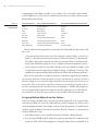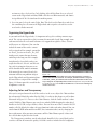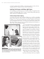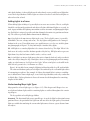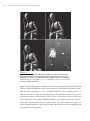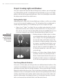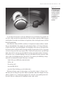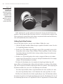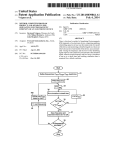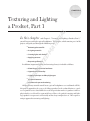
1
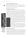
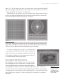
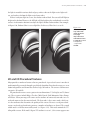
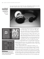
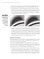
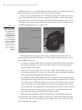
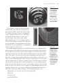
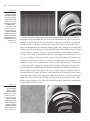
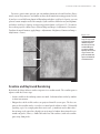
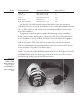
Chapter 1 AL Texturing and Lighting a Product, Part 1 RI In this chapter and Chapter 2, “Texturing and Lighting a Product, Part 2,” TE you will texture and light a pair of headphones. This chapter, which contains part 1 of the project, will guide you through the following steps: Reviewing the scene file ■■ Assigning materials ■■ Creating lights and shadows ■■ Applying textures ■■ Raytracing reflections TE D MA ■■ GH In addition, important lighting and texturing theory is included as follows: Material types and critical attributes ■■ Hypershade functionality ■■ Lighting techniques and Maya light types PY RI ■■ Procedural textures ■■ Scanline and raytraced rendering CO ■■ Although many tutorials would treat a pair of headphones as a traditional still life, this project approaches the scene as if selling a product. In the realm of business, a product is a good or service that fulfills the need of a particular market. A product is often a physical object a seller offers a potential buyer. Hence, the goal of texturing and lighting a product is to present it aesthetically so that a buyer might desire it. This requires a unique approach to texturing and lighting. 2 ■ Chapter 1: Texturing and Lighting a Product, Part 1 Project: Reviewing the Scene File Before starting the texturing process, review the scene file and its contents. Open the headphones-start.ma scene file from the ProjectFiles/Project1 folder on the DVD. The scene hierarchy, surface UV texture space, camera setup, and unique light box geometry should all be examined before proceeding further. Checking the Hierarchy and UVs Figure 1.1 (Left) Hypergraph view of the headphones hierarchy. (Right) Outliner view of the same hierarchy. Group nodes are indicated by the white trapezoid symbols. The headphones model is constructed from 16 polygon surfaces. The surface nodes are grouped together as a single hierarchy (see Figure 1.1). You can view the hierarchy through the Hypergraph (Window ➔ Hypergraph: Hierarchy) or the Outliner (Window ➔ Outliner). You can select group or surface nodes through the Hypergraph and the Outliner. Technically speaking, a node is a construct that holds specific information and any actions associated with that information. In Maya, a node may be a surface, a light, a camera, a material, and so on. All the polygon surfaces carry a completed UV texture space. That is, each surface’s UV points are arranged in such a fashion that the texturing may begin immediately. The UV points are laid out as a single shell or as multiple shells surrounded by empty UV texture space (see Figure 1.2). You can examine the UV texture space of a surface by selecting the surface and choosing Window ➔ UV Texture Editor. Approaches for examining and utilizing the UV points and shells are discussed in the section “Creating Custom Bitmaps” later in this chapter. Technically speaking, UV texture space refers to a coordinate system that relates pixels of a texture map to positions on a surface. UV points represent the location of a polygon’s vertices within a UV texture space. If polygon faces overlap within the UV texture space, they share the same section of an assigned texture. Hence, the majority of surfaces in the headphones scene possess a UV layout that avoids overlapping faces. The few faces that are allowed to overlap are for small, unseen parts of the model. For an example of such overlapping, see the section “Creating Custom Bitmaps” later in this chapter. Working with Multiple Cameras The headphones scene file contains two perspective cameras: persp and Render. By default, the persp camera is included in every Maya scene file. You can use the persp camera to examine different parts of the model. The Render camera, on the other hand, is positioned and animated for the final render and should not be moved. To switch between persp and Render in any view panel, choose Panels ➔ Perspective ➔ camera name from the view panel menu. Note that the Render camera has the Resolution Gate option activated. The Resolution Gate appears in the view panel workspace as a green box with a grayed-out outer area (see Project: Reviewing the Scene File ■ 3 Figure 1.3). The box indicates the outer edge of the render; surfaces outside the box will not render. To toggle the Resolution Gate on or off for any camera, choose View ➔ Camera Settings ➔ Resolution Gate from the view panel menu. To manipulate the persp camera, select the persp node in the Hypergraph or Outliner and use the standard transform tools. You can also interactively move the camera with the Alt key and mouse buttons in a perspective view panel. Figure 1.2 (Left) The UV Texture Editor view of the Ear_Pad_R surface. A single UV shell occupies the entire UV texture space. The dark gray area represents the 0-to-1 UV range, whereby a texture is tiled one time. (Right) The UV Texture Editor view of the Ear_Cup_R surface. Two UV shells fill a portion of the UV texture space. In this case, UV points are selected and appear as green dots in Maya. The render resolution of the scene file is set to 640 × 360, which is one-half the size of HD 720 (1280 ×720). This is suitable for test renders. We will raise the resolution to 1280 ×720 toward the end of this chapter. In addition, the anti-aliasing render quality will be switched from low quality to high quality. Examining the Light_Box Geometry The headphones are surrounded by a large cube named Light_ Box. Real-world light boxes (or light tents) are small structures covered with fabric or other translucent material that diffuses incoming light (see Figure 1.4). Because the diffused light arrives from a multitude of directions, the subject is evenly lit and does not produce harsh shadows. As such, product photographers and videographers often employ light boxes. As an added bonus, light boxes allow for the creation of a “seamless background,” in which there is no obvious horizon line. Figure 1.3 Render camera view. Grayed-out areas outside the box of the Resolution Gate do not render. 4 ■ Chapter 1: Texturing and Lighting a Product, Part 1 Figure 1.4 In this chapter, you’ll use the Light_Box cube to create large specular highlights and reflections in the plastic and metal of the headphones. In Chapter 2, you’ll have the chance to illuminate the scene by using the Light_Box cube’s material attributes and the Final Gathering rendering option. (Top) The Light_Box cube. (Bottom) A real-world light box Material Types and Critical Attributes Materials, sometimes referred to as shaders, are small programs that determine the surface qualities of the geometry they are assigned to. In common terms, surfaces are described as rough, smooth, shiny, dull, and so on. A material uses a shading model, which is a mathematical algorithm that simulates the interaction of light with a surface. Working with Lambert, Blinn, Phong, Phong E, and Anisotropic Materials The Lambert material is considered a “parent” material in Maya. That is, four other Maya materials (Blinn, Phong, Phong E, and Anisotropic) inherit common attributes from the corresponding Lambert node (see Figure 1.5). Material Types and Critical Attributes ■ 5 The shared attributes include the following: Color Color determines its namesake. You can enter specific red, green, and blue values by clicking the color swatch and updating the Color Chooser window. For more information on the Color Chooser window, see the “Adjusting Colors and Transparency” section later in this chapter. Transparency Much like Color, Transparency uses a color swatch. By default, Transparency employs a scalar (grayscale) range in which black is opaque and white is transparent. However, you are free to choose any color value through the Color Chooser window. Ambient Color Ambient Color represents diffuse reflections arriving from all other sur- faces in a scene, as well as reflections from participating media (particles suspended in air, such as dust, smoke, or water vapor). To simplify the rendering process, the diffuse reflections are assumed to be arriving from all points in the scene with equal intensities. In practical terms, ambient color is the color of a surface when it receives no direct light. A high Ambient Color value will reduce the contrast of an assigned surface. Figure 1.5 Attributes shared by Lambert, Blinn, Phong, Phong E, and Anisotropic materials Incandescence Incandescence creates the illusion that the surface is emitting light. The color value of the Incandescence attribute is added to the color value of the Color attribute, thus making the material appear brighter. (You can use the Incandescence attribute to contribute light to a scene when using the mental ray renderer and the Final Gathering option; this is demonstrated in Chapter 2.) Bump Mapping At the point of render, bump maps perturb surface normals along the core of a surface (the central section facing the camera). They do not, however, affect the surface’s silhouette edge. For example, in Figure 1.6, a primitive sphere is assigned to a bump-mapped material. While the core of the sphere appears craggy, the sphere’s silhouette edge remains perfectly smooth. Nevertheless, the bump effect can often sell the idea that a surface is rough. When the Bump Mapping attribute is mapped, middle-gray values (0.5, 0.5, 0.5 on a 0 to 1.0 RGB scale) have no effect. Higher values cause peaks, and lower values cause valleys to form. For a demonstration of the bump effect, see the section “Procedurally Mapping Bumps” later in this chapter. Diffuse The term diffuse refers to that which is widely spread and not concentrated. Hence, a real-world diffuse surface appears matte-like and does not create highlights or specular “hot spots.” This is because of the presence of myriad surface imperfections that scatter light in a random fashion. For example, paper and cardboard are diffuse surfaces. In Maya, the Diffuse attribute controls the degree to which light rays are reflected in all directions. A high Diffuse Figure 1.6 A bump-mapped sphere renders with a craggy core and a smooth silhouette edge. 6 ■ Chapter 1: Texturing and Lighting a Product, Part 1 value produces a bright surface. A low Diffuse value causes light rays to be absorbed and thereby makes the surface dark. Translucence, Translucence Depth, Translucence Focus The Translucence attribute, in conjunc- tion with Translucence Depth and Translucence Focus, simulates the diffuse penetration of light into a solid surface. In the real world, you can see the effect when holding a flashlight to the palm of your hand. Translucence naturally occurs with hair, wax, fur, paper, leaves, and human flesh. The Translucence attribute is discussed further in Chapter 4, “Texturing and Lighting a Character, Part 2.” Adding Specularity Figure 1.7 The Specular Shading section of a Blinn material The Lambert material does not possess specularity. Specularity is the consistent reflection of light in one direction that creates a “hot spot” on a surface. In CG programs, specularity is emulated by creating a specular highlight. In Maya, specular highlights are controlled through a material’s Specular Shading section (see Figure 1.7). The Specular Shading section is carried by Phong, Phong E, Blinn, and Anisotropic materials. All four materials share the following specular highlight attributes: Specular Color Specular Color sets the color of the specular highlight. Reflectivity Reflectivity controls the intensity of raytraced reflections and reflections simulated with the Reflected Color attribute. By default, the Maya Software renderer does not raytrace. For an introduction to raytracing, see the “Project: Raytracing Reflections” section later in this chapter. Reflected Color If the Reflected Color attribute is set to any color other than black or is mapped, a simulated reflection is applied directly to the assigned surface. Reflected Color does not require raytracing to function. The Reflected Color attribute is demonstrated in Chapter 5, “Texturing and Lighting a Vehicle, Part 1.” Whereas the Blinn material controls the specular highlight size with the Eccentricity attribute, Phong uses the Cosine Power attribute, and Phong E uses the Roughness and Highlight Size attributes. The Anisotropic material controls the size, shape, and rotation of its specular highlight with the Angle, Spread X, Spread Y, and Roughness attributes. The Anisotropic highlight can assume circular, vertical, or horizontal patterns (see Figure 1.8). Technically speaking, an anisotropic surface is one that reflects light unevenly; in such a case, the unevenness is dependent on direction. Real-world anisotropic surfaces possess parallel channels, grooves, fibers, or tube-like structures. Human hair, brushed metal, and choppy water therefore fit the anisotropic category. If a surface creates specular highlights that are elongated and perpendicular to the channels/grooves/fibers/tubes, it is anisotropic. Material Types and Critical Attributes ■ 7 Keep in mind that 3D specular highlights are an artificial construct. Real-world specular highlights are actually reflections of intense light sources, such as a day sky or a bright lamp. The intensity of the Maya specular highlight is controlled by the Specular Roll Off (Blinn), Whiteness (Phong E), and Fresnel Index (Anisotropic). With the Phong material, you can adjust the specular intensity by changing the Specular Color. Figure 1.8 Using Specialized Materials In addition to Lambert, Blinn, Phong, Phong E, and Anisotropic, Maya offers several specialized materials. These are available in the Maya section of the Hypershade Create tab. In addition, a large number of mental ray materials are included in the mental ray section. Although the mental ray renderer can render either Maya or mental ray materials, the Maya Software renderer can render only Maya materials. Nevertheless, while texturing and lighting the headphones, we’ll work solely with Maya materials. Information on mental ray materials is included in Chapter 7, “Texturing and Lighting an Environment, Part 1.” Of the specialized Maya materials, Surface Shader, Use Background, and Layered Shader are perhaps the most useful. Descriptions of each follow: Surface Shader The Surface Shader material is a “pass-through” node. It carries no shad- ing properties and does not take into account any lights or shadows. A surface assigned to a Surface Shader material will appear self-illuminated. Hence, the material is appropriate for any surface that needs to retain a maximum intensity regardless of the scene’s lighting. For example, a half-sphere assigned to a Surface Shader with a sky photo mapped to its Color attribute does not need to be lit. As a working example, a Surface Shader material will be assigned to the Light_Box geometry later in this chapter. Use Background The Use Background material picks up the color of the camera’s Background Color attribute (which is black by default) or an image plane attached to the camera. If you assign Use Background to surfaces that are receiving shadows, the shadows are trapped in (Left) Nonspherical highlight of Anisotropic material. (Middle) Anisotropic highlight on human hair. (Right) Anisotropic reflection on choppy water 8 ■ Chapter 1: Texturing and Lighting a Product, Part 1 an alpha channel and the RGB channels remain black. This offers a handy means to render shadows as a separate render pass. For a demonstration of the Use Background material and render passes, see Chapter 6, “Texturing and Lighting a Vehicle, Part 2.” For a demonstration of image plane use, see Chapter 5. Layered Shader The Layered Shader material allows you to combine two or more materials. For a demonstration, see Chapter 7. Hypershade Functionality C D A B E Figure 1.9 The Maya 2011 and 2012 Hypershade window with (A) Create tab rollout column, which includes the Favorites, Maya, mental ray, and Autodesk Materials (2012) sections, (B) node list column, which is filtered by selections within the Create tab rollout column, (C) Input And Output Connections button, (D) node tabs, and (E) work area Maya 2011 introduced a newly designed Hypershade window (Window ➔ Rendering Editors ➔ Hypershade). Nevertheless, the window’s tabs, menus, and work areas remain virtually identical to earlier versions of the software. In addition, Maya 2012 uses the same Hypershade layout as Maya 2011. Figure 1.9 illustrates the key areas of the window. In Maya 2011 and 2012, the Create tab is broken into two halves: a rollout column and a node list column. The rollout column filters what appears in the node list column. For example, if you click the word Surface under the word Maya, the node list column shows only standard Maya materials. Creating a New Material To create a new material, click one of the material icons in the Create tab. The new material is added to the Materials tab. To access the material’s attributes in the Attribute Editor, click the material icon in the Materials tab (if the Attribute Editor is closed, double-click the material icon). To rename the material, update the name cell at the top of the material’s Attribute Editor tab. Assigning a Material To assign a material to a surface, select the surface, RMB+click the material icon in the Hypershade window, and choose Assign Material To Selection from the marking menu. You can also MMB+drag the material icon and drop it on top of a surface in a view panel; however, this method is less precise and is prone to incorrect surface assignment. When selecting a surface, it’s generally best to make your selections through the Hypergraph: Hierarchy or Outliner windows. If you select surfaces through a view Project: Assigning Materials panel, do so while the Select By Object Type button is activated on the Status Line (see Figure 1.10). If the Select By Hierarchy And Combinations button is activated instead, you may inadvertently select a group node. If a material is assigned to a group node, all the group node’s children automatically inherit the same material. Exploring Shading Networks A B C ■ 9 D Figure 1.10 Selection buttons on the Status Line include the (A) Select By Hierarchy And Combinations button, (B) Select By Object Type button, (C) Select By Component Type button, and (D) object type/component type option buttons. Any material you create is part of a larger shading network composed of multiple nodes. The nodes are represented as square icons in the Hypershade node tabs and work area. Some nodes are provided automatically and are necessary for basic rendering. Others arrive as you add texture maps. To view a shading network, go to the Materials tab of the Hypershade, RMB+click a material icon, and choose Graph Network from the marking menu. The network is revealed in the work area (see Figure 1.11). Initially, several nodes are hidden. To see the entire network, select the visible nodes in the work area and click the Input And Output Connections button (see Figure 1.9 earlier in this chapter). It may be necessary to select all the visible nodes and click the button several times. Within the work area, you can delete node connections or add new ones. For more information, see Chapters 5 and 6. You can change the view within the work area by using the camera controls (Alt key and mouse buttons). If the work area becomes cluttered, you can clear it by choosing Graph ➔ Clear Graph from the Hypershade menu. Project: Assigning Materials After examining the scene file, the first important step to texturing and lighting is the creation of new materials and their assignment to surfaces. As such, you must decide what types of materials to create. In addition, you must determine whether surfaces will share assignments. After material assignments have been made, you can adjust the materials’ Color and Transparency attributes. Figure 1.11 A shading network revealed in the Hypershade work area Choosing Material Types Generally, it’s best to match the Maya material type to the real-world material the surface is emulating. For example, if a material needs a specular highlight, a Lambert material 10 ■ Chapter 1: Texturing and Lighting a Product, Part 1 is inappropriate and a Blinn is suitable. As such, Table 1.1 lists each of the surfaces found in the headphones scene file, the real-world material it will try to emulate, and the recommended Maya material type. Table 1.1 Recommended material types Surface Name R e a l- Wo r l d M at e r i a l R e co m m e n d e d M aya M at e r i a l Slider Junction Wire Foam Ear_Cup Ear_Pad Grommet Head_Pad Light_Box (wall) Chromed metal Black plastic Black rubber Gray cell foam Black plastic Thin, bunched white leather Semitransparent yellow plastic Plastic stamped to simulate leather Translucent white fabric Phong Blinn Blinn Lambert Blinn Blinn Blinn Blinn Surface Shader You can take one of two approaches to determine the total number of materials needed for a scene: • Create a new material for each surface. For example, assign the Foam_L surface to a Foam_L_Color material and assign the Foam_R surface to a Foam_R_Color material. This allows each surface’s material to be adjusted separately. However, the Hypershade may become difficult to manage if a scene is complex and contains numerous surfaces. • Assign a single material to every surface that shares the same look. For example, create a single Foam material and assign it to both the Foam_L and Foam_R surfaces. This simplifies the contents of Hypershade but limits flexibility when adjusting attributes. Either of these approaches is suitable for this project. Should one approach prove limiting, you can delete materials, reassign materials, or create new materials at any time. To delete a material, simply select its icon in the Hypershade Materials tab and press the Delete key. If a material is deleted, any surface assigned to it will not render until it is assigned to one of the other surviving materials. Note that newly created primitives, NURBS, and polygon surfaces are automatically assigned to the Lambert1 material. Although you can edit Lambert1, you cannot delete it. You can assign a surface to a new or different material at any time. Assigning Multiple Materials to One Surface When you assign a polygon surface to a material, all the polygon faces are assigned to the same material. However, if you select individual faces before assigning, the surface can be assigned multiple materials. For example, with the Light_Box geometry, it would be preferable to assign the floor to one material and the walls and ceiling to a second material. To do so, follow these steps: 1. In the Hypershade, create a new Blinn material and Surface Shader material. 2. In a view panel, RMB+click the Light_Box geometry and choose Face from the marking menu. Shift+click all the polygon faces along the floor. If you accidentally select Project: Assigning Materials ■ 11 an incorrect face, deselect it by Ctrl+clicking. After all the floor faces are selected, return to the Hypershade window, RMB+click the new Blinn material, and choose Assign Material To Selection from the marking menu. 3. In a view panel, select the entire Light_Box. This deselects the floor faces and selects the remaining faces. Return to the Hypershade and assign the selected faces to the new Surface Shader material. Organizing the Hypershade As you work with the Hypershade, it’s important to keep the resulting contents organized. The easiest way to achieve this is to name the materials clearly. For example, name each material after the real-world substance it’s supposed to replicate. Thus, Chrome and Foam are useful names. You can also include the name of the surface a material is assigned to. For example, you might use Plastic_Junction or Leather_Ear_Pad. Avoid generic names that may become confusing in the long run. For example, it might not be clear which surfaces are assigned to Plastic1, Plastic2, and Plastic3. One trick is to imagine that your scene will be handed off to another animator; if the materials are named clearly, the Figure 1.12 animator will have no problem navigatMaterials created for the headphones scene. Each material is assigned to ing the Hypershade and determining how surfaces that share the same look. For example, the Wire material is assigned to the Wire_L, Wire_R, and Cord surfaces. Note that the material names are the materials are assigned. For example, easy to interpret. A sample Maya file is saved as headphones-step1.ma in the Figure 1.12 shows materials created for the ProjectFiles/Project1 folder on the DVD. For a color version of the figure, headphones scene file. see the color insert. Adjusting Colors and Transparency After you’ve assigned materials to all the surfaces in the scene, adjust the Color attribute for each material. Match the colors listed in Table 1.1 earlier in this chapter as well as those illustrated in Figure 1.12. To access the Color Chooser, click the Color attribute’s color swatch. With the Color Chooser, you can select a color by LMB+dragging the color wheel handles or the R/G/B (red/green/blue) sliders. You can also enter values into the R/G/B number cells. By default, the color scale runs from 0 to 1.0 for each color channel. You can switch from the RGB color model to an HSV (hue/saturation/value) one by changing the lower-right menu. After you move your mouse off the Color Chooser panel, it closes and the selected color is placed in the swatch. The Transparency attribute, on the other hand, should be left set to 0 (black) unless a surface calls for the namesake quality. Of all the surfaces included in the headphones 12 ■ Chapter 1: Texturing and Lighting a Product, Part 1 scene file, the grommets alone should be a semitransparent plastic. As such, set the corresponding material’s Transparency color swatch to a medium gray. Lighting Techniques and Maya Light Types Successful lighting in animation depends on a wealth of techniques developed for cinematography and still photography. This necessitates an understanding of Maya light types and the equivalent real-world lights they emulate. Understanding Product Lighting As mentioned earlier in this chapter, light boxes (light tents) are useful for evenly lighting products that fit within their structure. However, the Light_Box geometry included in the headphones scene cannot provide illumination at this point (although it will contribute to specular highlights and reflections). We will activate the illumination capability of the Light_Box in Chapter 2 by using mental ray and Final Gathering. In the meantime, we will use other real-world lighting techniques. Because the goal of this project is to light the headphones aesthetically, we can copy lighting approaches applied by glamour photography and music video videography. One common technique of such media requires the addition of a strong, diffuse key light or lights placed beside or close to the camera. A single light might take the form of a fluorescent ring that circles the camera. Alternatively, two equally intense lights might be placed on either side of the camera and softened by translucent “soft boxes” or diffusion material (see Figure 1.13). Such lights may also be bounced off reflective cards or purpose-built reflective umbrellas. By aligning the lights with the camera, visible shadows are minimized. For a human, this results in the reduction of noticeable wrinkles and similar flaws. For a product, this ensures that the parts of the product are clearly seen; that is, no part is made obscure by darkness. On a psychological level, a brightly lit subject with few shadows often produces a Figure 1.13 positive reaction. Conversely, a poorly lit subject with (Top) A model is lit by two lights placed on either side of the camera. deep, dark shadows is associated with gloomy or disThe left light carries a soft box. Bounced light from the white walls works as a back light. (Bottom Left) The result of similar lighting on turbing subject matter such as film noir or horror. a face. (Bottom Right) The result of similar lighting on a product (in When a light is referred to as diffuse, its light this case, a restaurant meal) rays diverge and overlap in such a way as to produce Lighting Techniques and Maya Light Types soft-edged shadows. A focused light, on the other hand, creates parallel rays of light that create hard-edged shadows. Diffuse lights are often referred to as soft. Focused lights are often referred to as hard. Adding Lights to a Scene When adding lights in Maya, it’s generally best to create one at a time. That is, each light should be satisfactorily positioned and adjusted before additional lights are created. As such, it pays to follow the lighting conventions used for cinematic and photographic lighting: Each light is assigned a specific task that ultimately determines its position and intensity. The tasks are generally broken down into the following: Key A key light is the most intense light in the scene. The key light’s source is generally identifiable (the sun, a lamp, and so on). The key light usually produces the strongest shadow in the scene. If two light sources are equally intense, as is the case with the glamour photography in Figure 1.13, they both may be considered key lights. Fill A fill light is a secondary light that is less intense than the key. This light “fills in” the dark areas of a subject and the shadows produced by the key. Fill lights often represent light from a key that has bounced off a surface, such as a wall. Rim A rim light is an intense light source that arrives from the back of a subject so that it strikes the subject along the edge. Rim lights, when used in photography and cinematography, are also known as back lights or hair lights. When a rim light is used to fill in the dark side of a person’s face, it is known as a kicker. Figure 1.14 is included as an example of lighting in Maya that adds a key, fill, and rim light. The color and shadow quality of each light is determined by the real-world light source it’s attempting to replicate. For example, if a Maya directional light is acting as a midday sun, it should arrive from a high angle, create hard-edged shadows, and carry a color that is slightly blue. (Light replication is discussed in more detail throughout the remaining chapters of this book.) Understanding Maya Light Types Maya provides six basic light types (see Figure 1.15). This chapter and Chapter 2 use an area light and volume light, and the remaining lights are utilized throughout the remaining chapters. The key qualities of each light type follow: Directional The directional light creates parallel rays. As such, the light has direction but not position. Hence, the position of the light icon will not affect the light quality. Directional lights are suitable for emulating the sun or other light sources that are a great distance from the subject. ■ 13 14■ ■ Chapter 1: Texturing and Lighting a Product, Part 1 Rim Fill Key Figure 1.14 (Top Left) Mannequin lit by a key light. (Top Right) Mannequin lit by key and fill. (Bottom Left) Mannequin lit by key, fill, and rim. (Bottom Right) Positions of all three lights as seen in a Top view panel. The three lighting scenarios are included as key.ma, key_fill.ma, and key_fill_rim.ma in the ProjectFiles/Project1/ Reference folder on the DVD. Point The point light produces omnidirectional rays originating from the light icon. Point lights are similar to lightbulbs or other sources that have a small, physically spherical shape. Spot The Maya spot light re-creates a spotlight found on a stage or motion picture set. Thanks to its conical shape, the spot light produces naturally divergent rays. In general, the light can emulate artificial sources that are close to the subject. Because of the spot light’s cone, it has an identifiable falloff from 100 percent to 0 percent intensity. The size of the cone is controlled by the Cone Angle attribute. The softness of the cone edge is set by the Penumbra attribute, which is 0 by default. Note that the scale of the spot light icon does not affect its light quality. Lighting Techniques and Maya Light Types Figure 1.15 (Top Row) Maya light types. (Bottom Row) The corresponding real-world lighting scenarios emulated by Maya lights. From Left to Right: A directional light re-creates the parallel rays of an unobstructed sun; a point light acts like a lightbulb with omnidirectional rays originating from a specific point; a spot light simulates the divergent rays of a real-world spotlight from film and stage; an area light duplicates light arriving from a rectangular plane, such as a window; an ambient light acts like bounced light (in this case, window light bounced off a floor); a volume light functions as a point light, but the illuminated surfaces must be placed within the light’s volume shape. Area The area light possesses a rectangular icon and can be scaled in either the X or Y direc- tion. Hence, area lights can emulate a source that is transmitted through a plane with a fi xed size. For example, an area light might re-create sunlight arriving through a window or a bank of lightbulbs placed behind a rectangular marquee. Area lights are the most physically accurate of the basic Maya light types. As such, the light intensity is affected by the distance and angle of the light icon in relation to lit surfaces. Although an area light is represented by a rectangular icon, it actually functions as an array of point lights. This array causes the area light to be fairly soft. Nevertheless, area lights operate in one direction; this is indicated by the small “pointer” extending from the light icon’s center. Ambient The ambient light is extremely soft and produces little, if any, variation in inten- sity. By default, the light is a mixture of omnidirectional and directional rays. The light’s Ambient Shade attribute controls this mixture. If Ambient Shade is lowered from the default 0.45 to 0, the light becomes equally intense at all points within a scene; this leads to a flat, “toon” look. If Ambient Shade is raised to 1.0, the light radiates from the light icon and is identical to a point light. Ambient lights are suitable as fi ll and are usually inappropriate as a key. Volume The volume light acts as a point light but is contained within the volume of the light’s icon. You can scale the icon to any size. By default, the icon is spherical, but you can change it to a cylinder or cone through the light’s Light Shape attribute. By default, the light’s intensity tapers from the icon center to the icon edge. The rapidity of this taper is controlled by the Color Range and Penumbra gradients. For a surface to be lit by a volume light, it must rest within the interior of the light icon. For a demonstration of the volume light’s unusual functionality, see Chapter 2. ■ 15 16 ■ Chapter 1: Texturing and Lighting a Product, Part 1 Project: Creating Lights and Shadows After you’ve adjusted the material Color and Transparency attributes, you can begin lighting. Although Maya provides a default light when no light nodes are present, the light quality is not driven by any particular light source. Hence, the default light is not suitable for judging assigned materials or added textures. Setting the Key Light Although you have a fairly wide selection of light types in Maya, we will use an area light to serve as the key for the headphones scene. The soft quality of the area light makes it suitable for product lighting. Use the following steps to create and place the light: Figure 1.16 Scaled and positioned area light that will serve as the key, as seen from the Top and Front view panels 1. Choose Create ➔ Lights ➔ Area Light. The new area light is placed at 0, 0, 0. Select the light and interactively scale it so that it’s 10, 10, 20 units in X, Y, Z. For greater precision, you can enter values into the Channel Box. Rename the light Key. You can enter a new name through the top cell of the Channel Box while the light is selected. 2. Position and rotate the light so that it is in front of and slightly higher than the Render camera icon (see Figure 1.16). The light should point in the same direction as the Render camera. The direction the area light is pointing is indicated by the “pointer” extending from the light’s center. Note that the Render camera is animated and moves in a short arc around the headphones. Use the Timeline controls to see where the camera starts and stops. 3. Render a test. To do so, choose Window ➔ Rendering Editors ➔ Render View and choose Render ➔ Render ➔ Render from the Render View menu. At this point, the render settings are set to low quality. We will raise the quality after we add shadows. Fine-Tuning Material Attributes After you’ve set the key light, you can begin to fine-tune additional material attributes. First, examine the overall brightness of the surfaces in the render. If the surfaces are consistently too bright or too dark, adjust the Key light’s brightness. To do so, open the light’s Attribute Editor tab (with the light selected, press Ctrl+A) and change the Intensity attribute value. If individual surfaces are too bright or too dark, adjust the corresponding material’s Diffuse attribute. Lower Diffuse values produce darker surfaces. If necessary, further adjust each material’s Color attribute. For example, in Figure 1.17, the Key light’s intensity is set to 0.4, while several materials have had their Diffuse and Color values lowered. Project: Creating Lights and Shadows ■ 17 Figure 1.17 Headphones lit with an area light serving as a key. The Diffuse and Color attributes of several materials are adjusted. A sample file is saved as headphones -step2.ma on the DVD. As you adjust the materials, render out additional tests in the Render View window. To save time, render out only the region of interest. You can define a region by LMB+dragging in the Render View render area to form a red region box. After releasing the mouse, click the Render Region button. Aside from the Color and Diffuse attributes, it’s important to adjust attributes controlling specular highlights. For example, the render shown in Figure 1.17 features black plastic parts with intense specular highlights. The highlights reduce the overall contrast for the plastic surfaces and thus make them appear milky. In particular, the Ear_Cup geometry carries large areas that verge on pure white. To defeat the overly intense specular highlights, adjust the Eccentricity, Specular Roll Off, and Specular Color attributes. Reducing Eccentricity creates a smaller highlight. Lower Specular Roll Off and/or Specular Color values reduce the highlight intensity. For the Ear_Cup geometry, the following settings work well (assuming the Key light’s Intensity is set to 0.4): Color: Dark gray (RGB values 0.02, 0.02, 0.02) Diffuse: 0.3 Eccentricity: 0.15 Specular Roll Off: 0.3 Specular Color: Medium gray (the default value) Each material may require its own unique set of specular settings (see Figure 1.18). Note that you can change the Specular Color to a nonwhite color. For example, the headphone’s grommets are a semitransparent plastic. By setting the corresponding material’s Specular Color to a yellow-gold, the highlight becomes more subtle. 18■ ■ Chapter 1: Texturing and Lighting a Product, Part 1 Figure 1.18 Eccentricity, Specular Roll Off, and Specular Color attributes of materials are adjusted. A sample file is saved as headphones -step3.ma on the DVD. For a color version of the figure, see the color insert. While adjusting the specular quality of each material, check each of the Reflectivity attributes. For any material that need not be reflective, set the Reflectivity attribute to 0. When raytracing is activated later in this chapter, any material with a nonzero Reflectivity value will automatically reflect within the scene. Adding Depth Map Shadows After the Key light is in place, you can create shadows. Follow these steps: 1. With the Key light’s Attribute Editor tab open, expand the Shadows section. Select the Use Depth Map Shadows check box. 2. Render a test. The shadow edge will appear jagged. This is partially because of the low-quality render settings. Choose Window ➔ Rendering Editors ➔ Render Settings. In the Maya Software tab of the Render Settings window, change the Quality menu to Production Quality. 3. Render a test. The overall quality of the render is improved. However, the shadow remains jagged. To remedy this, you can raise the light’s Resolution value. For example, in Figure 1.19, the Resolution is set to 2048. The higher the Resolution value, the smoother the depth map shadow edge will appear. However, Resolution alone will not affect the hardness or softness of the shadow edge. You can soften the shadow by adjusting the Filter Size attribute. When adjusting the Resolution and Filter Size, you can use the following rules of thumb: • For a hard-edged shadow, choose a high Resolution value and a low Filter Size value. • For a soft-edged shadow, choose a low Resolution value and a high Filter Size value. The Filter Size attribute blurs the shadow equally along its edge. The Resolution attribute determines the pixel size of a depth map bitmap written to disc. The bitmap is the view of the shadowing light written as a Z-depth buffer. With a Z-depth buffer, the distance from 2D and 3D Procedural Textures ■ 19 the light is encoded in various shades of gray; surfaces close to the light receive higher values, and surfaces far from the light receive lower values. If there is only one light in a scene, the shadow renders black. You can add a fi ll light to brighten the shadow. However, the fi ll light will also brighten the unshadowed area of the surface. An alternative solution is to adjust the light’s Shadow Color attribute. For example, in Figure 1.20, Shadow Color is set to a light blue. In this case, Filter Size is set to 32. Figure 1.19 (Left) Detail of depth map shadow with default 512 Resolution. (Right) Improved shadow with 2048 Resolution. A sample file is saved as headphones -step4.ma on the DVD. 2D and 3D Procedural Textures Maya provides a number of textures that are procedural. A procedural texture is one that is mathematically generated through a predefi ned algorithm. Procedural textures are resolution independent and do not have defi ned edges or borders. The textures fall into two categories: 2D and 3D. 2D procedural textures create a pattern in two dimensions: U (left/right) and V (down/ up). These textures include Bulge, Checker, Cloth, Fractal, Grid, Mountain, Noise, Ramp, and Water. When you map a 2D texture to the attribute of a material, two nodes are created and connected to the material node. The fi rst node is the texture node, which carries the attributes that determine the quality of the texture. Because several procedural textures are based on fractal noise patterns, a number of attributes are shared. The second added node is a 2d Placement utility node (see Figure 1.21). This node controls the UV tiling of the texture. If the node’s Repeat UV attribute is set to 1, 1, the texture appears one 20 ■ Chapter 1: Texturing and Lighting a Product, Part 1 Figure 1.20 time across the surface in the U and V directions. Additionally, the 2d Placement utility node offers attributes to offset, mirror, or rotate the procedural pattern. Filter Size is set to 32, and Shadow Color is set to a light blue. A sample file is saved as headphones -step5.ma on the DVD. Figure 1.21 (Top) A 2d Placement utility node, automatically named place2dTexture1, connected to a Noise texture node. (Bottom) The utility’s UV tiling attributes Note that two naming conventions are applied to any given node in Maya: a “nice” name and a “long” name. A nice name includes spaces and features capitalization. A long name carries no spaces and sometimes features a different word order. For example, 2d Placement is a nice name while place2dTexture is a long name. Nevertheless, 2d Placement and place2dTexture refer to the same node. The Hypershade work area uses the long naming convention to label the node icons. The Hypershade Create tab node list, however, uses the nice naming comvention. In contrast to procedural textures, several 2D textures are based on bitmaps imported by the user; these include File, Movie, and PSD File. When mapped to an attribute, a bitmap-based 2D texture is connected to its own 2d Placement utility node. When a 3D procedural texture is mapped to an attribute, a 3d Placement utility node is connected to the shading network. The node is visible in each view panel as a green placement box (see Figure 1.22). By default, the box is placed at 0, 0, 0 and is 2 × 2 × 2 units in size. The utility determines the color of each assigned surface point by locating the point’s position within or relative to the placement box. This process is analogous to a surface dipped into a square bucket of swirled paint or a surface chiseled from a solid cube of veined stone. Hence, the scale, translation, and Project: Applying Textures ■ 21 rotation of the placement box affects the way in which the texture appears across the assigned surface. If the surface is transformed relative to the box or deforms over time, the texture will change. To avoid such a change, it may be necessary to parent the 3d Placement node to the surface. More drastically, you can convert 3D textures to 2D textures through the Convert To File Texture tool. 3D textures include Brownian, Cloud, Crater, Granite, Leather, Marble, Rock, Snow, Solid Fractal, Stucco, Volume Noise, and Wood. Project: Applying Textures After basic material attributes are adjusted under the Key light, you can begin adding textures. Both procedural textures and custom bitmap textures will lend the render greater complexity. Because textures will add fine detail to the various surfaces, it’s necessary to increase the render resolution to accurately gauge the result. Open the Render Settings window and change the Presets menu, in the Image Size section, to HD 720. Procedurally Mapping Bumps At the present stage of this project, the surfaces of the headphones appear perfectly smooth. To defeat this perfection, you can map Bump Mapping attributes with various procedural textures. For example, to add a leather-like bump to the Head_ Pad geometry, follow these steps: Figure 1.22 (Top) A 3d Placement utility node, automatically named place3dTexture1, connected to a Solid Fractal texture node. (Bottom) The corresponding placement box displayed in a view panel 1. Open the Hypershade window and click the material assigned to the Head_Pad surface. (The material is named Leather_Head_Pad in the included sample scene files.) In the material’s Attribute Editor tab, click the Bump Mapping attribute’s checkered Map button. 2. In the Create Render Node window, click the Leather texture icon. To simplify the node list column, click the phrase 3D Textures under the word Maya in the rollout column. After the Leather texture is selected, three nodes are added to the material’s shading network: a Leather node, a Bump 3d node, and a 3d Placement node. (To view the network, follow the instructions listed in the “Exploring Shading Networks” section earlier in this chapter.) 3. Render out a test. A leather-like bump appears across the Head_Pad surface (see Figure 1.23). At this point, the leather pattern is small and too deep. To reduce the bump depth, open the Attribute Editor tab for the Bump 3d node. Change the Bump Depth attribute to 0.3. Render a test. 22■ ■ Chapter 1: Texturing and Lighting a Product, Part 1 Figure 1.23 (Top) Detail of render after addition of the Leather texture as a bump map. (Bottom) Render after the adjustment of the Bump 3d and Leather node attributes. A sample file is saved as headphones -step6.ma on the DVD. 4. Open the new Leather node’s Attribute Editor tab. Reduce the Cell Size to 0.8 to enlarge the overall size of the pattern. Despite this adjustment, vertical lines appear across the surface. This is because of the regularity of the leather cells. To defeat this, change the Leather’s Randomness attribute to 1.0 (see Figure 1.23). Although the addition of the Leather bump map increases the realism of the head pad, it does not create the illusion that the pad was constructed out of multiple pieces. To create the illusion that the edges of the pad are stitched, you can apply a Grid texture as a bump map with the following steps: 1. Select the Head_Pad surface and choose Window ➔ UV Texture Editor. Note how the surface is split into multiple UV shells (see Figure 1.24). The top shell contains the polygons sitting on the top of the pad. The middle shell contains the polygons sitting on the bottom of the pad. The bottom shell, which takes the form of a square, includes all the polygon faces along the forward and back edges of the pad. To see which polygon faces a shell includes, RMB+click in the UV Texture Editor and choose Face from the marking menu. Proceed to select faces in the UV Texture Editor by either LMB+clicking individual faces or LMB+dragging a selection box around multiple faces. The selected faces are highlighted in the view panels. Note that each of the edge faces shares exactly the same UV texture space. This means that every edge face will receive the same exact part of the texture assigned to the surface. Project: Applying Textures ■ 23 2. Open the Hypershade. Create a new Blinn material. Name the new Blinn Leather_Pad_Edge or something equally appropriate. Return to the UV Texture Editor. Clear the face selection by clicking on an empty area of the UV space. LMB+drag a selection box around the bottom square shell. All the edge faces are selected. Return to the Hypershade. RMB+click the new Blinn node and choose Assign Material To Selection. Although the pad’s UV texture space contains the faces for the entire pad, only the selected edge faces are assigned to the new Blinn. The old material’s assignments of the remainder of the pad are not changed. 3. Open the new Blinn node’s Attribute Editor tab. Change the attributes to match the material assigned to the remainder of the pad. (The included sample scene files use the Leather_Head_Pad material.) Click the checkered Map button beside the Bump Mapping attribute. In the Create Render Node window, click the Grid texture icon. Grid, Bump 2d, and 2d Placement nodes are added to the Blinn’s shading network. Render a test. Small divots appear along the pad edges (see Figure 1.25). Figure 1.24 The UV shells of the Head_Pad surface Figure 1.25 (Left) Detail of render after addition of the Grid texture as a bump map. (Right) Render after the adjustment of the 2d Placement and Blinn node attributes. A sample file is saved as headphones -step7.ma on the DVD. 4. To refine the bump pattern, open the new 2d Placement node’s Attribute Editor tab. Change the Rotate UV attribute to 45. This creates diagonal grid lines. Open the Grid node’s Attribute Editor tab. Change UV Width to 0.3, 0.3. This thickens the grid lines so they will become more visible. To further exaggerate the bump, readjust the Blinn node’s attributes. For example, the render on the right side of Figure 1.25 sets Diffuse to 0.2, Eccentricity to 0.16, and Specular Roll Off to 0.4. Render a test. An impression of stitching is created. 24■ ■ Chapter 1: Texturing and Lighting a Product, Part 1 The Foam surface, which represents the material covering the headphone’s built-in speakers, can also benefit from a bump-mapped noise. To add such a bump, follow these steps: Figure 1.26 1. In the Hypershade, select the material assigned to the Foam_L and Foam_R surfaces. (The included sample scene files use the Foam material.) Open the material’s Attribute Editor tab and click the checkered Map button beside the Bump Mapping attribute. In the Create Render Node window, click the Noise texture icon. Render a test. Blobbish pits appear on the Foam surfaces (see Figure 1.26). (Left) Detail of render after addition of the Noise texture as a bump map. (Right) Render after the adjustment of the 2d Placement, Bump 2d, and material node attributes. A sample file is saved as headphones -step8.ma on the DVD. 2. To make the surfaces appear as if they are made of closed-cell foam that possesses tiny, bubble-like air pockets, adjust the 2d Placement node connected to the new Noise texture node. Change the Repeat UV attribute to 10, 10 to create smaller “cells.” To further randomize the noise pattern, select the Stagger check box. To reduce the depth of the bump, change the Bump 2d node’s Depth attribute to 0.5. Last, fine-tune the Color and Diffuse attributes of the material assigned to Foam surfaces. Figure 1.26, for example, has Color set to dark gray (0.19, 0.19, 0.19 in RGB) and Diffuse set to 0.36. Creating Custom Bitmaps Although procedural textures are suitable for creating semirandom patterns, they cannot re-create specific designs or features. Hence, the addition of printed logos for the headphones requires the creation of custom bitmaps. To create a custom bitmap, it will be necessary to export the UV texture space of a targeted surface from Maya and bring it into a digital paint program. For example, to create a bitmap texture for a headphone junction (the plastic part between the chrome slider and the head pad), you can use Adobe Photoshop with the following steps: 1. In Maya, select the Junction_R geometry as a surface and choose Window ➔ UV Texture Editor. From the editor’s menu, choose Polygons ➔ UV Snapshot. The UV Snapshot window opens, allowing you to export the UV texture space as a bitmap (see Figure 1.27). Use the File Name browse button to choose a file name and directory location. Change the Size X and Size Y attribute values to an appropriate resolution. Project: Applying Textures ■ 25 In this case, it’s best to choose a resolution that will match the desired resolution of the final texture. For example, 1024 ×1024 is appropriate for a small piece of geometry when rendering at HD 720. Change the Image Format menu to a format that’s supported by a digital paint program (such as Photoshop). For example, JPEG is a commonly used format that produces sufficient quality for the texture-painting process. (If you choose an image format that supports alpha, such as Targa or TIFF, the UV information will be written to an alpha channel.) Click the OK button. The UV texture space is written out with the name and location defined by the File Name attribute. 2. Launch Photoshop. Open the UV snapshot file you just wrote out. The UV texture space appears with the UV shells laid out in white over a black background (see Figure 1.28). By default, only the 0 to 1.0 UV space is included. U runs left to right, and V runs down to up with 0, 0 at the bottom-left corner. (If UV shells or UV points fall outside the 0 to 1.0 area, they receive a repeated part of the texture.) Note that the tubes running through the center of the Junction_R surface overlap the surface sides. Overlapping faces share the same part of any assigned texture. For this reason, you usually want to avoid such overlap. However, in this situation, the overlap is unimportant because the walls of the tubes are not seen by the rendering camera. 3. In Photoshop, double-click the Background layer in the Layers panel. The New Layer window opens. Enter a new name, such as UV Snapshot, into the Name field, and click OK. This converts the locked Background layer into a layer that you can reposition in the layer stack. Choose Layer ➔ New ➔ Layer. Double-click the new layer to open the New Layer window. Enter a new name, such as Texture, into the Name field, and click OK. LMB+drag the UV Snapshot layer to the top of the layer stack. Change the UV Snapshot layer’s blending mode menu from Normal to Screen. The Screen blending mode allows the white lines of the snapshot to appear over the lower texture layer. An example PSD file with this setup is included Figure 1.27 The UV Snapshot window Figure 1.28 A UV snapshot of the Junction_R surface as seen in Photoshop. The arrows point to several areas where polygon faces overlap in the UV texture space. 26■ ■ Chapter 1: Texturing and Lighting a Product, Part 1 Figure 1.29 (Left) Detail of color variation added to the black representing the plastic. The contrast is exaggerated for print. The actual texture variation is more subtle. (Right) Photo of screw head pasted twice into texture, as seen in Photoshop. A finished texture is included as Junction_Color.tga in the ProjectFiles/ Project1/Textures folder on the DVD. as UV_setup.psd in the ProjectFiles/Project1/Reference folder on the DVD. Proceed to paint on the lower texture layer. Note that the general color of the texture does not need to be pure black. Even though the junction is composed of black plastic, you can add subtle scratches, smudges, or slight color variations (see Figure 1.29). 4. To add additional realism, feel free to cut and paste from photo bitmaps. For example, the junction geometry includes two cylindrical holes that represent the locations of screws. Instead of painting screw heads by hand, cut and paste from a photo bitmap of a screw (you can take the photo yourself or find one through a stock photo or 3D texture website). To cut and paste, choose File ➔ Open and retrieve the photo bitmap. Switch to the opened photo bitmap by clicking on the top bar of its window. Using the Lasso tool, draw a selection marquee around the screw head. Choose Edit ➔ Copy. Switch back to the texture you started with. Choose Edit ➔ Paste. Press Ctrl+T to reveal the transformation handle. Interactively scale, position, and rotate the pasted screw head into location over a screw hole indicated by the UV snapshot (see Figure 1.29). 5. To create a specific logo on the side of the junction, you can use Photoshop’s Type tool or cut and paste from a bitmap that already carries text. You can leave the text a solid color. On the other hand, you can add color variation to make the text appear more complex. For example, to give the sense that the printed logo uses metallic flake paint, you can use masking tools to cut a noisy layer into a text-like shape (see Figure 1.30). To do so, create a new layer and add white text. Again, you can use the Type tool or cut and paste from a bitmap that already carries text. Create a new layer and paint a pattern that emulates gold flake paint. If this is too difficult to paint, cut and paste from a photo that has a similar noisy pattern (for example, glitter or sand). If the photo’s colors are incorrect, choose Image ➔ Adjustments ➔ Color Balance and fine-tune the red, green, and blue mixture. After the gold flake paint layer is completed, switch back to the text layer by clicking on the corresponding layer name in the Layers panel. Using the Magic Wand tool, click within the white area of one letter. Choose Select ➔ Similar. This selects all the white text. Choose Select ➔ Inverse. Return to the gold flake paint layer. Choose Edit ➔ Cut. The gold flake paint is cut out in the shape of the text. Project: Applying Textures ■ 27 Figure 1.30 6. When you’ve finished painting the various layers, choose Layer ➔ Flatten Image. Choose File ➔ Save and select a Maya-compatible file format. Targa or TIFF are both high-quality formats. When choosing a filename, strive for clarity. For example, name the file Junction_Color. Return to Maya. Open the Hypershade, select the material assigned to the Junction_R surface, and open its Attribute Editor tab. Click the Color checkered Map button. In the Create Render Node window, click the File texture icon. File and 2d Placement nodes are added to the shading network. Open the new File node’s Attribute Editor tab. Click the Image Name attribute’s Browse button and retrieve the texture you wrote out from Photoshop. If the Junction_L surface is assigned to a separate material, repeat this process with that material. Render a test. The screw heads and logo should appear in the correct locations (see Figure 1.31). It’s important to remember that Maya does not store bitmap textures in its scene file. That is, when you save an .mb or .ma Maya scene file, the bitmap textures are left in their original location and in their original state; the file simply records the location of the texture as a line of text. Therefore, it’s best to save the textures in a logical and accessible location. For example, if the scene files are saved to C:/ProjectFiles/Project1, save the bitmap textures to C:/ProjectFiles/Project1/Textures. If you open a scene file and discover that a File texture is missing or otherwise renders black, you will need to reload it. To do so, open the File texture node’s Attribute Editor tab and click the Reload button below the Image Name attribute. If Reload fails, use the Image Name Browse button to relocate the texture file. When opening Chapter 1 sample scene files, you can avoid missing bitmap textures by first choosing File ➔ Project ➔ Set (Left) White text over black (Middle) Bitmap photo of gold glitter. (Right) Photo cut out in the shape of the letters with the application of the Magic Wand, selection, and cut tools. A finished texture is included as Junction_Color.tga in the ProjectFiles/ Project1/Textures folder on the DVD. Figure 1.31 Custom bitmap texture applied to Junction material (as seen on frame 36). For a color version of the figure, see the color insert. 28■ ■ Chapter 1: Texturing and Lighting a Product, Part 1 Figure 1.32 and browsing for the Project1 folder whether the folder remains at its original location on the DVD or is located on a drive after the DVD contents have been copied. When creating custom bitmaps, you’re not limited to color. For example, you can create the illusion that the plastic junction is composed of two halves with a central groove by painting a new texture and mapping it to the Bump Mapping attribute of the associated material. The groove requires a black line on the texture while the unaffected areas are fi lled with 50 percent gray (see Figure 1.32). (Left) Custom bump texture. (Right) Junction rendered with a bumped groove along the side. A sample file is saved as headphones -step9.ma. A finished texture is included as Junction _Bump. tga in the Project Files/Project1/ Textures folder on the DVD. When painting the bump map texture, it may be difficult to determine where the groove should be positioned in relation to the UV snapshot. To make this process easier, you can follow these steps: 1. In a Maya view panel, RMB+click the Junction_L or Junction_R surface and choose Face from the marking menu. Proceed to Shift+click the faces that would make a suitable location for the groove. 2. Open the UV Texture Editor. The selected faces will be isolated. Make a note of the face locations within the UV texture space. If need be, you can switch back and forth between Maya and Photoshop while painting the texture. 3. Even though the anti-aliasing quality has been set to high, you may notice that small details appear soft. In part, this is because of the automatic activation of the Use Multi Pixel Filter attribute. Multi-pixel filtering averages the pixels within a render as a postprocess. This helps prevent anti-aliasing issues such as stair-stepping. Unless the render is destined for video output, however, the filtering can make the render excessively blurry. You can turn off the filtering by deselecting the Use Multi Pixel Filter check box in the Maya Software tab of the Render Settings window. Other parts of the headphones model can benefit from custom bitmaps mapped to Color attributes. For example, the plastic ear cups are a suitable location for a large logo (see Figure 1.33). To create such a bitmap, you can follow steps similar to those listed at the beginning of this section. Project: Applying Textures ■ 29 Figure 1.33 (Left) Custom color texture. (Right) Ear cup rendered with logo. A sample file is saved as head phones -step10.ma. A finished texture is included as Ear_ Cup_Color.tga in the ProjectFiles/ Project1/Textures folder on the DVD. The headphone ear pads can also benefit from a custom bump texture. The Pad_L and Pad_R surfaces utilize the full UV texture space with a single UV shell for each surface. Because each polygonal surface is doughnut-shaped, there is a seam where the left and right sides of the UV texture space meet in 3D space. You can locate this seam by RMB+clicking in the UV Texture Editor, choosing Face from the marking menu, and Shift+clicking all the faces that form a vertical column on the far left or far right side. The corresponding faces are highlighted in the view panels (see Figure 1.34). Real-world headphone ear pads are often bunched leather that creates numerous parallel grooves. Because the UV shell for the pad geometry is square, such bunches must be painted as vertical black, gray, and white streaks, as shown in Figure 1.35. (When it comes to bump maps, 50 percent gray leaves the surface unaffected, while high values create ridges and low values create grooves.) You can create such streaks in Photoshop by manually using the Brush tool or cutting and pasting from a photo that contains similar vertical features. As a bonus, you can add horizontal white dashes to replicate stitching that occurs near the pad edge. For example, Figure 1.35 illustrates a completed texture. Note that a texture need not be perfectly square to function. In fact, with the pad geometry, it’s easier to fit in a sufficient number of vertical lines when the texture has a greater number of pixels in the U direction than in the V direction. After the texture is mapped to the Bump Mapping attribute of the appropriate material, it’s necessary to adjust the Bump 2d node’s Bump Depth and the material’s Diffuse and specular attributes. For Figure 1.35, the following settings are used: Bump Depth: –0.2 (a negative value inverts the bump result) Diffuse: 0.4 Eccentricity: 0.2 Specular Roll Off: 0.2 Figure 1.34 (Left) Leftmost column of faces of the Pad_L surface are selected in the UV Texture Editor. (Right) Corresponding faces are highlighted orange in the persp view panel. This indicates the seam where the left and right sides of the UV texture space meet. 30■ ■ Chapter 1: Texturing and Lighting a Product, Part 1 Figure 1.35 (Left) A custom bump texture with vertical lines to replicate bunched leather and short horizontal dashes to re-create stitching. The texture is included as Ear_ Pad_Bump.tgain the Project Files/ Project1/Textures folder on the DVD. (Right) Detail of render after the addition of the bump texture. A sample file is saved as headphones -step11.ma. Figure 1.36 (Left) Generic Specular Roll Off texture. The texture is included as Generic_Spec.tga in the Project Files/ Project1/Textures folder on the DVD. (Right) The result of the texture mapped to the ear cups and grommets. A sample file is saved as head phones-step12.ma. Another material attribute that benefits from custom bitmaps is the Specular Roll Off. By mapping the Specular Roll Off, you can create the illusion that the surface is scratched, smudged, or slightly imperfect. In this situation, it is not necessary to make a specific map for a specific piece of geometry. Instead, you can create a “generic” bitmap that can be mapped to multiple materials and hence multiple surfaces. For example, you can map a lowcontrast, grayscale, noisy bitmap to the Specular Roll Off attributes of the materials assigned to the Junction_L, Junction_R, Cup_L, Cup_R, Grommet_L, and Grommet_R surfaces (see Figure 1.36). If the pattern found within the bitmap appears too similar between surfaces, you can offset each instance by adjusting the Offset UV or Rotate UV attributes of the connected 2d Placement nodes. If a surface is relatively small, such as Grommet_L or Grommet_R, you can use a portion of the texture by reducing the Repeat UV values below 1, 1. Note that the Eccentricity and Specular Color attributes will require adjustment after Specular Roll Off is switched from a solid color to a mapped file. In addition to adjusting the Eccentricity and Specular Color to affect the size and intensity of a highlight, you can lighten or darken the generic specularity texture within Maya. To darken the texture, lower the texture node’s Color Gain attribute value. To lighten the texture, raise the texture node’s Color Offset value. Color Gain and Color Offset are located in the texture node’s Color Balance section. If you raise the Color Offset while lowering the Color Gain, you reduce the contrast found within the texture. Scanline and R aytraced Rendering To create a generic noise pattern, you can combine photos of real-world surfaces. Rusty metal, stucco, dirty concrete, and similar surfaces often contain interesting patterns. In fact, if you layer several different photos in Photoshop and adjust each layer’s Opacity, you can generate a more complex result. For example, if you stack three different rusty metal photos and reduce each layer’s Opacity, an interesting pattern forms (see Figure 1.37). To convert the result to grayscale, choose Layer ➔ Flatten Image and Image ➔ Adjustments ➔ Desaturate. To adjust the overall contrast, apply Image ➔ Adjustments ➔ Brightness/Contrast or Image ➔ Adjustments ➔ Curves. ■ 31 Figure 1.37 Three photo bitmaps of rusty metal are placed on three different layers in Photoshop. The top and middle layers are given reduced Opacity values, leading to a more complex result after the layers are flattened and desaturated. Scanline and Raytraced Rendering By default, the Maya Software renderer operates in a scanline mode. The scanline process operates with these basic steps: • Surfaces visible to the rendering camera are noted. Occlusion of one surface by another is taken into account. • Polygon faces of the visible surfaces are projected into 2D screen space. The faces are processed in scanline order. A scanline is a row of pixels within a render. (Technically speaking, a pixel is a sample point that carries an x, y coordinate and a color value; for an image to be stored in a digital system, it must be broken down into a discrete number of pixels.) Hence, a 1280 ×720 render has 720 scanlines (with each scanline possessing 1280 pixels). 32 ■ Chapter 1: Texturing and Lighting a Product, Part 1 • The final color of each pixel within a scanline is based on the material qualities of the polygon face found within the pixel. In addition, the surface’s relationship to lights and cast shadows is taken into account. • To optimize memory usage, the scanline approach is often broken into tiles. The size of any given tile is based on the number and complexity of surfaces found with a particular area of the camera’s view. For example, when you render with Maya Software in the Render View window, the bottom-center section of the view is the first to appear. In contrast, the raytracing process fires off a virtual ray from the camera eye through each pixel of the view plane. Essentially, the view plane is a 2D grid that’s perpendicular to the axis of the camera lens (that is, the grid is coplanar to the virtual film back). The grid possesses the same dimensions as the pixel size of the chosen render resolution. The first surface a ray hits determines the pixel color. That is, the material qualities of the surface are used in the shading calculation of the pixel. If the surface is reflective or refractive, additional rays are created at the surface intersection point. One ray represents the reflection, and one ray represents the refraction. These rays continue until they intersect another surface. Additional reflection and/or refraction rays are born at the new intersection point if the associated material is reflective or refractive. To prevent an infinite number of rays from being born, limits are placed on the total number of permitted rays. Refraction differs from reflection in that a refractive ray travels through a surface. Real-world refractive materials, such as glass or water, are perceived as transparent or semitransparent. With Maya Software, raytracing is activated via the Raytracing check box found within the Raytracing Quality section of the Maya Software tab of the Render Settings window (see Figure 1.38). The number of times an initial ray is allowed to reflect or refract is controlled by the Reflections and Refractions attributes. For example, if Reflections is set to 3, a ray is allowed to create three addiFigure 1.38 tional reflection rays. Along those lines, any reflective surface is allowed to reflect The Raytracing Quality section of the Maya Software tab in the Render any ray that hits it so long as that ray has been previously reflected two times or Settings window less. Additionally, you can control the number of raytraced shadows that appear in recursive reflections or retractions by setting the Shadows attribute. If Shadows is set to 2, the render creates one recursive raytraced shadow in any reflection or refraction. If Shadows is set to 1.0, standard shadows appear but no raytraced shadows appear within reflections or refractions. In contrast, depth map shadows appear in all reflections and refractions and are unaffected by the Shadows attribute. For more information on raytraced shadows, see Chapter 2. Figure 1.39 Blinn, Phong, Phong E, and Anisotropic materials possess a Raytrace The Raytrace Options section of a Blinn Options section (see Figure 1.39). material Project: R aytracing Reflections A list of the most critical attributes and their functionality follows: Refractions Activates refractivity for the surface assigned to the material. For the refrac- tivity to be visible, the material’s Transparency attribute must be set above 0. Refractive Index Determines the degree of refractivity present. If set to the default 1.0, no refraction occurs. In the real world, a refractive index is a number that indicates the change in the speed of light when the light ray crosses the boundary between two materials. For example, water has a refractive index of 1.33, which means light slows by 25 percent. The actual equation is (speed of light in vacuum)/(speed of light in water) or 1.0/0.75, which equals 1.33. The change in speed affects the perceived angle of the light rays, which causes refracted surfaces to appear bent. For example, a straw placed in a glass of water appears bent below the water line. Lists of real-world materials and their refractive indexes are easily found on the Internet. Refraction Limit and Reflection Limit Are local material overrides for the Reflections and Refractions attributes found in the Render Settings window. The lower value between matching attributes determines the number of reflective or refractive rays that the surface assigned to the material is permitted to generate. For example, if Reflection Limit is set to 1, the assigned surface is allowed to reflect any ray that hits it so long as that ray has not been reflected previously. If Reflection Limit is set to 4, an assigned surface is allowed to reflect any ray that hits it so long as that ray has been reflected previously three times or less. If refractions and/or reflections are missing from a surface when it renders, yet the Reflections and Refractions attributes in the Render Settings window have high values, raise the Refraction Limit and/or Reflection Limit values. Project: Raytracing Reflections Thus far, no surface in the headphones scene is creating reflections. To create reflections, you must select the Raytracing check box in the Maya Software tab of the Render Settings window. After Raytracing is activated, all surfaces are potentially reflective. To alter this behavior, you must adjust the Reflectivity attribute of each material in the scene. If you prefer that a surface does not reflect, change the Reflectivity attribute of its assigned material to 0. To increase the strength of a surface’s reflection, raise the Reflectivity value of its assigned material; you can exceed the default limit of 1.0 by entering a higher value into the number cell. Because reflectivity is also affected by Specular Roll Off and Specular Color, those attributes may require adjustment. Table 1.2 lists the recommended reflective surfaces and the corresponding Specular Color and Reflectivity settings (the Specular Roll Off attributes were mapped in the section “Creating Custom Bitmaps” earlier in this chapter). ■ 33 34■ ■ Chapter 1: Texturing and Lighting a Product, Part 1 Table 1.2 Recommended Reflectivity settings Figure 1.40 Final Chapter 1 render. A sample file is saved as head phones-step13. ma on the DVD. For a color version of the figure, see the color insert. Surface Name SPecular color reflectiVity Slider_L/R Junction_L/R Cup_L/R Grommet_L/R Light_Box (Floor material) Mid-gray (0.4, 0.4, 0.4) Mid-gray (0.4, 0.4, 0.4) Mid-gray (0.35, 0.35, 0.35) Gold (0.5, 0.4, 0) Default gray (0.5, 0.5, 0.5) 1 0.1 0.15 0.2 0.3 Note that the Color of the material assigned to the Slider surface does not matter. When Reflectivity is set to 1.0, the reflection obscures the surface color completely. In this case, the Slider surfaces are able to reflect the surrounding Light_Box as well as nearby parts of the headphones. It’s important to adjust the attributes within the Raytracing Quality section of the Render Settings window. For this project, a Raytracing value of 2, a Refractions value of 0, and a Shadows value of 2 is sufficient. (Refractions are not needed for the headphones model.) Additionally, the Raytracing Options section of each material should be examined. For this project, a Reflection Limit of 2 is sufficient for each reflective material. (For more information on the raytracing attributes carried by a material and the Render Settings window, see the prior section of this chapter.) The addition of raytracing concludes the first part of “Lighting and Texturing a Product.” As such, your render should look similar to Figure 1.40. In Chapter 2, we’ll add an additional light, change the shadow type, switch to the mental ray renderer, activate Final Gathering, and fine-tune the materials and textures.