1
. Digital Zoom Camera Series
P/N : 3810-0046B (Ver.0506E) Color Zoom Camera Series
® Design and specifications
are subject to
change without notice.
DSP
Day & Night Color Camera
192X 220X
Digital Zoom
COLOR ZOOM CAMERA SERIES
DIGITAL POWER ZOOM
OWNER'S MANUAL
OSL DIGITAL
On-Screen Display
al . User Information
CAUTION
RISK OF ELECTRIC SHOCK
DO NOT OPEN
CAUTION! TO REDUCE THE RISK OF ELECTRIC SHOCK,
DO NOT REMOVE COVER (OR BACK).
NO USER-SERVICEABLE PARTS INSIDE.
REFER SERVICING TO QUALIFIED
SERVICE PERSONNEL.
Explanation of two Symbols
The lightning flash with arrowhead symbol,
Within an equilateral triangle, is intended to
alert the user to the presence of un-insulated
"dangerous voltage" within the product's
enclosure that may be of sufficient magnitude to constitute a
risk of electric shock to persons.
The exclamation point within an equilateral
triangle is intended to alert the user to the
presence of important operating and
maintenance-(servicing) instructions in the
literature accompanying the appliance.
THE GRAPHIC SYMBOLS WITH SUPPLEMENTAL MARKING ARE
ON THE BOTTOM OF THE SYSTEM.
"WARNING-TO PREVENT FIRE OR SHOCK HAZARD, DO NOT
EXPOSE THE UNIT TO RAIN OR MOISTURE"
2 Digital Power Zoom
INFORMATION
This equipment has been tested and found to comply with limits for a
Class A digital device, pursuant to part 15 of the FCC Rules.
These limits are designed to provide reasonable protection against
harmful interference when the equipment is operated in a commercial
environment.
This equipment generates, uses, and can radiate radio frequency energy
and, if not installed and used in accordance with the instruction manual,
may cause harmful interference to radio communications.
Operation of this equipment in a residential area is likely to cause
harmful interference in which case the user will be required to correct
the interference at their own expense.
WARNING
The manufacturer could void the user's authority to operate the
equipment.
CAUTION - To prevent electric shock and risk of fire hazards:
* Do NOT use power sources except for that specified.
* Do NOT expose this appliance to rain or moisture.
This installation should be made by a qualified service person
and should abide to all local codes.
COLOR VIDEO CAMERA 3
a .Contents
4
1. Model Description cccccccccccccccccs 5
2. Safety and Precautions sseccccccccces 6
3. Features **seoscoocoococcoccoccecee 7
4. Rear View and Part Names <e....0..0 8
5. Installation **.es00cscococcoccocccece. 10
6. Communication Protocol «+«-.=..oosoo 18
7. On-Screen Display + +seescccccocoooo 19
8. Menu Format +Ä0Ä00000000000000000000 21
9. Menu Format Table ceeecccccccccccccs 22
10. Specifications 00000 00000000000000000 23
Digital Power Zoom
2 | 1. Model Description
e Thank you for purchasing this COLOR ZOOM CAMERA.
Before operating the camera, confirm the camera model and proper
power voltage. In order to understand the manual thoroughly,
we'll introduce our model descriptions.
Model Type Signal Power | D&N | UTP | Communication
0. |(Rear)| System Input DSS |Output System
EY |NTSCHiIgh| DC12V | O | X |RS-485/PTZ Controller
C9 | PAL/High | DC12V 0 X _|RS-485/PTZ Controller
C |NTSC/High| DC 12V 0 | X RS-232C
C | PAL/High | DC 12V 0 | X RS-232C
€ |NTSC/High| DC 12V X X |RS-485/PTZ Controller
EY | PAL/HiIgh | DC12V X X |RS-485/PTZ Controller
C |NTSC/HI9h | DC 12Vv X | X RS-232C
C | PAL/High | DC 12V X | X RS-232C
@ | NTSC/High | AC24V/DC12V| 0 X _|RS-485/PTZ Controller
@ | PAL/High |AC24V/DC12V| O | X |RS-485/PTZ Controller
(©) | NTSC/High | AC24V/DC12V| 0 0 RS-485
(©) | PAL/High |AC24WDC12V| 0 0 RS-485
@ | NTSC/High|AC24V/DC12V| X | X |RS-485/PTZ Controller
@ | PAL/High |AC24V/DC12V| X X _|RS-485/PTZ Controller
(D) |NTSC/High | AC24V/D012V | X 0 RS-485
(D) | PAL/High |AC24V/DCI2V| X 0 RS-485
A) INTSC/Normal DC 12V X X |RS-485/PTZ Controller
O | PAL/Normal| DC 12V X X |RS-485/PTZ Controller
O INTSCNormal AC24V/DC12V| X X [RS-485/PTZ Controller
© |PAL/Normal [AC24WDC12V| X | X |RS-485/PTZ Controller
COLOR VIDEO CAMERA 5
a (2. Safety and Precautions
6
m Avoid using the camera in extreme temperature environments.
Using the camera in temperatures exceeding 50°C or below -10°C may
lessen picture quality or cause the camera to malfunction.
m Avoid using the camera in high humidity environments.
Using the camera in places with high humidity may lessen picture quality
because of moisture on the lens.
m Avoid using the camera in unsteady lighting.
The camera will not work properly in places with great changes in
illumination intensity, such as fluorescent lamps.
= Make sure no foreign substances get on the front glass of the camera.
Do not disassemble the camera and prevent foreign substances
from getting into the camera.
m Make sure that the camera is not exposed to an intense light
source such as direct sunlight.
It may damage the CCD.
= Camera may be damaged if dropped or subjected to strong impact.
m Keep camera dry.
The camera will be damaged if immersed in water.
m Avoid using the camera in the presence of oil and gas.
The camera will be damaged if oil or gas penetrates the exterior.
= Caution
- Smear or blooming (when bright areas spreads out) may occur when
photographing in strong light, i.e. car headlights, etc.
- Make sure that you are using a compatible power adapter before
connecting it to the camera.
Digital Power Zoom
ae 3. Features
* High Resolution
The horizontal resolution of 480/ 380 TV lines can be achieved
by using a high density CCD having effective 410K/ 270K pixels,
which provides clean, noiseless and reliable pictures.
Built-in Power Zoom Lens
Subjects can be magnified up to 192/ times
with be 16x/ 22x) optical zoom and 12x/ (10x) digital zoom.
Al/Fuzzy Control Circuit with DSP
Advanced DSP(Digital Signal Processor) technology automatically
adjusts operations such as Iris, white balance flexibly adapting to
environmental conditions.
Remote Control through RS-232C/RS-485 Interface
Remote control operations are possible through RS-232C/ RS-485
interface for Focus and Zoom control.
- In addition, the unit lets you command white balance and exposure
manually using RS-232C/ RS-485 interface.
PROTOCOL: Default, Pelco-D
OSD(On-Screen Display) Function
Wire Remote Controller (Option)
Digital Slow Shutter for full color surveillance under very
low light condition : 0.001Lux (at x 128 Field)
Day & Night Function : 0.1Lux
e Day & Night Model
Coax or UTP(Unshielded Twisted Pair) Video Transmission.
Built-in UTP Transmitter provide a significant advantage in labor/
material saving on installations.
e UTP Video Out Model
COLOR VIDEO CAMERA 7
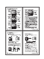
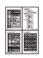
ae 4. Rear View and Part Names
U7: LE) DC 12V Input Model
@ Function О VIDE X O Video Out Jack
Setup Button ( ee on mm roi (©) \
О О О | © © Power LED
W(Y) O TS DISTANCE IN
OÖ =u @ Selection
Class 2 Only witc
22223] [2] | © power tput
ower Inpu
© gn Ere "969 [29°
D OZ E € @остМме
87:1) AC 24V/DC 12V Input Model
@ Function у О VIDEC 5) @ Video Out Jack
Setup Button lon CE Fo! ©
O 00 @ Power LED
ww) (Bow + oe IN |
“On Tm @ Selection
AC 24VV Switch
aesgale| lee 6) Power Input
ower Inpu
© Tal U OOOO] Ojo ) ) Terminal
@ © 7 FC еост2уе
Le) DC 12V Input Model
= N-—— O Video Out Jack
® Function 5 vos {OUT
Setup Button f f О ©
О — 6) Power LED
w(v) (POWE3) DISTANCE
O Con
O D23
ss В5232С | Class 2 Only
I @ Selection
Switch
witc
oo
aa 6) Power Input
© ©
990
© Control OJOLOILO ОО
Terminal ® © RD TD GND SZ Terminal
AI
WIE) UTP Transmisson Model
; т @ Video Out Jack
@ Function О ve OU \
Setup Button (2 7
№7 @ Power LED
Cone O TS fo | @ Selection
Control Oni O
© Terminal Switch
| ее ВЕ © Power Input
alo ower Inpu
Creel] 190 | Terminal
@ UTP Video 20 99 eme,
Output Terminal N — —Ñ—íÁm————
® Function Setup Button:
Functions can be setup using 5 buttons on the camera's rear panel.
T(A)
Also used to escape menu mode.
O O Ol >TELEWIDE Buttons : Used to choose the
w(v) desired menu item. It also moves the cursor
O up or down in the menu screen.
© NEAR/FAR Buttons : Used to change the parameter of the selected
ON EM Fo)
menu item. It also moves the cursor the left of right in the menu screen.
9 MENU Buttons : Used to access menu mode.
O VIDEO OUT Jack: Used to connect an external video monitor in jack.
@ Power LED: The LED turns on when power is supplied.
O Selection Switch:
21:08) © When the distance is far from camera to monitor,
set "Selection Switch" in 2 or 3. It shows more clear video on the monitor.
* Used to choose video output or UTP output.
® POWER Input Terminal
E Control Terminal
@ UTP Video Output Terminal: These terminals provide a composite
video output signal which may be transmitted over a twisted-pair
connection to furnished with a suitable receiver.
8 Digital Power Zoom COLOR VIDEO CAMERA 9
@_ 5. Installation
1. Connecting to Monitor * UTP Video Output Model
Connect the video out jack on the back of the product to the monitor. Connect the UTP video output terminal on the back of the product
to the monitor.
Camera Е . Camera Monitor(or DVR)
: Ÿ Monitor
O pry
con >» UY Selection Switch
o © © fot Video Output
О “to tm
CET) EXILE Class 2 Only
Se Ш -
* The method of connecting the camera to a monitor varies
depending on the model.
Please refer to the manual for your model. 300m(Max) UTP Receiver
* Connect the camera after switching off each piece of equipment. * When using UTP video output terminal, set "Selection Switch"
at the "UTP OUT".
* Change the 752/Hi-Z conversion switch of each piece of equipment
according to the following diagram- move the switch of the * When the distance is far from camera to monitor, set "Selection Switch"
intermediate video receiver to Hi-Z, and the end equipment to 759. in the middle.
The picture will show a better image.
Camera Intermediate End Equipment * Connect UTP (Unshielded Twisted Pair) wire to the UTP output of the
TA) VIDEO OUT Video Recelver camera directly.
ome (© VIDEO VIDEO UTP transmitter is included in the camera therefore additional UTP
о © gow de 50 MHz 79 Hi-Z transmitter is not necessary.
as 3
Bes EEE our n cu * UTP receiver is necessary to connect UTP wire to Monitor or DVR.
6 я * When connecting UTP wire, make sure the polarity of the video signal.
* Use UTP wire "CAT5 24AWG" to have the best transmission quality.
10 Digital Power Zoom COLOR VIDEO CAMERA 11
2. Connecting to Power
Each model has different power specification, please check the name of
the model and power specification before connecting to power source.
Please refer to the sticker identifying the model, which is attached on the
product, for power specification.
* For DC 12V Power Type
- The wire is polarized. Be careful of polarity.
- Use DC 12V === power source.
vlass 2 Only
Tía) VIDEO OUT
CABLE
wiv) DISTANCE
O Lo tm
023
Class 2 Only
ooo
22) 2) ©) 5),
o|olo|olo]
®@ 6 z_F ci HB
Resistance of copper wire [at 20°C (68°F)]
Copper wire size
(AWG)
#24 #22 #20 #18
(0.22m) (0.33mw) — (0.52mm) (0.83m)
Resistance(&2/m) 0.078 0.050 0.030 0.018
| Voltage Drop(V/m) | 0.028 | 0.018 | 0011 | 0006 |
. As voltage may drop according to the length of electric cord as above
table, a camera may malfunction if too long output line of adaptor is
connected to the camera.
- Voltage for camera operation: DC 12V + 10%
- Voltage drops on above table are variable according to types of electric cord
and makers.
12 Digital Power Zoom
e For AC 24V / DC 12V Power Type
- Use AC 24Vv power source or DC 12V === power source.
Tía) VIDEO OUT
О
A
CABLE
w(v) DISTANCE
Ch 2
less Con
O Mza
CONTROLLER AC 24VV
oJoJo|o ©
ose 68e© .
O|O|O|O|O|;*
® 9 2 EC: et
JAI Power Supply
AG 24V
100m(Max)
* When using AC 24V power with UTP wire, it is possible to supply the
power within 100m.
* Use 4 wires by 2 pair of wires.
* When using DC 12V power, UTP wire can not be used for power line.
Notes
. Be sure to connect power after all the installation is done.
. Note that AC adaptor is not supplied with camera.
. Use only AC 24V | DC 12V UL listed class 2 power supply.
. Do not use power sources other than that specified.
COLOR VIDEO CAMERA 13
14
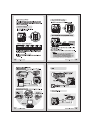
3. Camera Control Methods
ГСМ [7: 19) : Remote control using for PTZ controller.
* PTZ Controller
Pr
« [000000000000 e
00000000000007
00000000000000
< ооооооовооововово
00000000600
0.0.0...
pe
«©
"A" SK Jw 2a EYL Le 21) - Remote control using for RS-485.
* Pelco-D [= * Receiver &
Keyboard
> AT oc. Remote Control
e Signal (RS-485
* DVR System | = o
Digital Power Zoom
* DVR
* DVR-Connet to Serial PORT
(COM1 or COM2)
wn CED rm HB
OO =
wm Em SA
O Lo =
TRxD + (_)
TRxD -()—[ =] * Camera RS-485 Converter
* Keyboard (Pelco-D)
* Pelco-D Keyboard
COLOR VIDEO CAMERA” 15
o Receiver & Remote Control
* RS-485 Signal
90 8000
С 5
DDD)
OJOJO|O
® © ® ©
DC 12V, 500mA - White Terminal : O
©O—e—® - Black Terminal : ©
@ Camera Selection
o - After camera connects with receiver,
firstiy check camera 1.D.
I
© © © - Press camera |.D. number(1-39 buttons)
O © ©! on the top of wireless remote controller.
| | © Example: ZOOM IN
O © * |.D. No.5: Press 5 + <TELE>
' (0)! * |.D. No.15: Press <F1> +5 + <TELE>
SEQ “77 PAN *|.D. No.24: Press <F2> + 4 + <TELE>
* Caution : Usually camera 1.D. number
are selected from No.1 to No.39.
over 1.0. №.40, you will have a use limit.
- Initial camera 1.D. number is set up No.0
1 ©) when it takes out of manufacturer's warehouse.
* | D. No.34: Press <F3> + 4 + <TELE>
o 560)
[es
© (og) | | @ ® Menu (PROG): Shows/ Hides Menu.
CF) ET) (3) © (TELE):
@ (WIDE):
® (NEAR)
ФЕ “ak | Set data for the selected items.
16 Digital Power Zoom
| Moves up and down items.
N———oo—]————
Le AUD : Remote control using for RS-232C.
* PC (RS-232C)
* PC-Connet to Serial PORT
(COM1 or COM2)
1. Frame GND
2. RD
3. TD
4. DTR
5. Signal GND
6. DSR
7. RTS
8. CTS
9. RI
Camera Terminal | Controller Wire
KEY O WHITE
KEY O BLACK
COLOR VIDEO CAMERA 17
al 6. Communication Protocol
m PELCO "D" Byte Format -RS-485,2400bps,1 Start bit,8 data bits,1 stop bit,no parity
m Command Message
Function Zoom Tele
BYTE 1 | BYTE 2 | BYTE 3 | BYTE 4 | BYTE 5 | BYTE 6 | BYTE 7
MSG OxFF CamiD | 0x00 0x20 0x00 0x00 | Checksum
Function Zoom Wide
BYTE i | BYTE 2 | BYTE 3 | BYTE 4 | BYTE 5 | BYTE 6 | BYTE 7
MSG OxFF | CamiD | 0x00 0x40 0x00 0x00 | Checksum
Function Focus Near
BYTE1 | BYTE2 | BYTE3 | BYTE4 | BYTE 5 | BYTE 6 | BYTE 7
MSG OxFF— | CamiD | 0x01 0x00 0x00 0x00 | Checksum
Function Focus Far
BYTE i | BYTE 2 | BYTE 3 | BYTE 4 | BYTE 5 | BYTE 6 | BYTE 7
MSG OxFF | CamiD | 0x00 0x80 0x00 0x00 | Checksum
Function Menu On / Off
BYTE 1 | BYTE 2 | BYTE 3 | BYTE 4 | BYTE 5 | BYTE 6 | BYTE 7
MSG OxFF | CamiD | 0x40 0x00 0x00 0x00 | Checksum
Function Ромег Оп
ВУТЕ 1 | ВУТЕ 2 | ВУТЕ 3 | ВУТЕ 4 | ВУТЕ 5 | ВУТЕ 6 | ВУТЕ 7
MSG OxFF | CamiD | 0x88 0x00 0x00 0x00 | Checksum
Function Power Off
BYTE 1 | BYTE 2 | BYTE 3 | BYTE 4 | BYTE 5 | BYTE 6 | BYTE 7
MSG OxFF | CamiD | 0x08 0x00 0x00 0x00 | Checksum
Function Pelco D Stop
BYTE 3 | BYTE 4 | BYTE 5 | BYTE 6 | BYTE 7
| MSG | OxFF | CamiD | 0x00 | 0x23 | 0x00 | Ox5F |Checksum|
e V/D Keyboard (Set Preset + 98)
Function Menu On / Off
BYTE 1 | BYTE 2 | BYTE 3 | BYTE 4 | BYTE 5 | BYTE 6 | BYTE 7
| MSG | OxFF | CamiD | Ox00 | 0x03 | 0x00 | 0х62 |Checksum|
18 Digital Power Zoom
a (7. On-Screen Display
m Explanation of the On-Screen Display
The OSD (On Screen Display) is as follows:
p
(7 de Fi] PuB X10000 ID 255
1 23
4 5 6
WAIT
X132
8
—
. Focus 4. WBC(White Balance Control) Display
The [appear during the focus manual See Page 20.
mode.
5. Shutter Speed
2. Mirror Use to select the shutter speed.
When IMAGE MIRROR is ON state. The
image is displayed in the opposite direction. 6- Camera ID Display
The 4m appear during the mirror mode. See Page 20.
3. Back light Display 7. Wait Mode
In case the excessive light is behind the Indicates the camera stand-by mode
center object, it is necessary to prevent until the camera power turns on.
the center object from too much .
darkness. Turn the BACK LIGHT ON, 3 Example of Zoom, Brightness,
then the center object is not influenced Sharpness Display
by the back light. See Page 20.
COLOR VIDEO CAMERA” 19
FUNCTION | OSD Format DESCRIPTION
1 | Focus Mode | Nondisplay | Automatic focus mode
Es Manual focus mode
2 | Mirror Mode | Non display No screen inverted
фин Screen is inverted to the left or right
3 | Back Light Non display Back Light compensation off
A Back Light compensation mode
4 | WBC Mode Non display White Balance AUTO
Push Auto White Balance: In this mode
_— "Menu key" pressed, the white point traced
Pub automatically (PWB Auto Mode), "Menu Key"
released, the white point preserved currently
(PWB Manual Mode).
5 | Shutter Non display | Normal shutter (NTSC:1/60 PAL:1/50)
Speed 1/125 8 variable
1/10000 -
6 | Camera ID After input the identification number to each camera,
Multi-point control is available. (000—255)
7 | Wait Mode Wait Indicates the camera stand-by mode.
until the camera power turns ON.
8 | Zoom x16 : Optical Zoom only mode
Display x32 : Digital Zoom x 2 mode
x192 : Digital Zoom x 12 mode
8.1 | Sharpness —
Adjustment SHP jr] — x10
Mode Display
g.2 | Brightness
Adjustment © =] x18
Mode Display
20
Digital Power Zoom
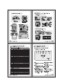
a 8. Menu Format
1. General Model <>
7
MENU |
1 BACKLIGHT OFF
[72 NEG/ POS | Can be changed
3 COLOR ON using the < / >
Move up and down >| 4 WB CONTROL | AUTO button.
using the TELE/ 5 SHUTTER 1/10000
WIDE button. 6 CAMERA 123
al _J
a NN
7 ZOOM START 1
8 ZOOM STOP 192
9 BRIGHTNESS 48
10 SHARPNESS 10
11 FOCUS AUTO
12 PROTOCOL DEF
13 INIT SET ON
END |
2. Day & Night Model
(MENU D
1 BACKLIGHT OFF
[22 SLOW SHUTTER FLD24
3 DAY/NIGHT OFF
4 WB CONTROL AUTO
5 SHUTTER 1/10000
6 CAMERA 123
\_ J
(MENU )
7 ZOOM START 1
8 ZOOM STOP 192
9 BRIGHTNESS 48
10 SHARPNESS 10
11 FOCUS AUTO
12 PROTOCOL DEF
13 INIT SET ON
| END )
COLOR VIDEO CAMERA | 21
iE 9. Menu Format Table
% : Day & Night Model
NO NAME FUNCTION
1 | BACKLIGHT Use to select BLC mode.
FF——>ON
2 | NEG/ POS Use to change NEGATIVE and POSITIVE mode.
ON : NEGATIVE mode OFF : POSITIVE mode
SLOW SHUTTER | Use under very low light condition for full color
surveillance.
O OFF——>FLD2——>———>FLD128
3 | COLOR Use the change color and monochrome of picture.
ON : Color mode = OFF : Black and White mode
DAY & NIGHT Use under low light condition for continuous
surveillance.
© Auto—— >ON—— > OFF
4 | WB CONTROL « AUTO : maintan best color condition by controlling
the change of color Automatic ly.
WB Range 2800°K ~ 8000
« PUSH AUTO(PWB) : Can find Whi Balance exactly
in case precise WB maintenance
is needed under any environment.
--Turn the AUTO mode, WB acts automatically.
--Turn the PUSH AUTO mode, WB doesn't act.
5 | SHUTTER Use to select the shutter speed 8 steps
NORMAL(NTSC:1/60, PAL:1/50),1/125, “17250, ---,1/10000
6 | CAMERA ID To connect a large number of camera, identification
number can be assigned to each camera control easily.
(OFF, 1-255 : total number of ID is 256)
CAUTION : Set the ID number of camera, then
the ID number is displayed continuously.
7 | ZOOM START Use to change the zoom start position.
8 | ZOOM STOP Use to change the zoom stop position.
9 | BRIGHTNESS Use to change the brightness of scene (0—48).
10 | SHARPNESS Use to change the contour of scene (0~15).
11 | FOCUS = AUTO : Set the focus mode to Auto mode.
: PUSH AUTO : Set the focus mode to Push Auto mode.
12 | PROTOCOL = DEF : Default
= P/D: Pelco-D
13 | INIT SET Set the initial mode ON, the changed data are renewed.
E 10. Specifications
Signal System
Signal System 525 Lines 625 Lines
Scanning System 2 : 1 Interlace
Scanning Frequency(H) 15.734 kHz 15.625 kHz
Scanning Frequency(V) 59.94 Hz 50Hz
Image Sensor 1/4 inch SONY IT CCD
Effective Pixels Number | 768(H) x 494(V)[Noma!510(H) x 49200) 1752{H) x 582{V)[Normal:500(H) x 562(V)]
S/N Ratio More than 48dB (AGC Off)
Resolution Horizontal : 480 TV Lines [Normal : 380 TV Lines]
Video Output Level 1.0 Vp-p (75 Ohms, composite)
Lens 16x (F1.4, 1=3.9~62.4mm)/ (22x (F1.6,1=3.9-—85.8mm))
Digital Zoom Ratio 12x (Total Zoom Ratio: 192x)/ (10x (Total Zoom Ratio: 220x))
Min. Shooting Distance 1 cm (Wide) / 1 meter (Tele)
Min. Illumination 1.0 Lux (30 IRE), 0.001 Lux (Day & Night Model)
Sync. System Internal
OSD(On Screen Display) On / Off
Shutter Speed (8 Steps) 1/60 ~ 1/10,000 Sec. 1/50 ~ 1/10,000 Sec.
Input/ Output Connector | Control: 5 Pin Terminal, Power: 2 Pin Terminal, Video: BNC
Power Consumption DC 12V (DC 9V—15V), Max. 5.4W / 450mA
(Option: AC24V/DC12V) | AC 24V (20V~28V) or DC 12V (11V~15V), Max 6W/ 0.5A
Dimensions (WxHXD) 58 x 58 x 103.4 mm /
Weight Approx. 300g
Reset the data to its shipping condition.
22
Digital Power Zoom
COLOR VIDEO CAMERA = 23