1
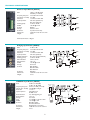
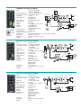
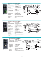
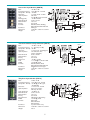
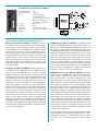
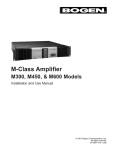
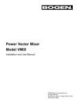
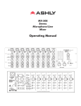
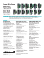
Input Modules
Models BAL2S,
BRG1R, LMM1S,
LMR1S, MAX1R,
MIC1S, MIC2S,
MIC1X, MIC2X,
SAX1R, TBL1S,
TEL1S, TNG1S
DESCRIPTION
Bogen’s advanced plug-in modules provide a wide range of functions to support a variety of applications.
These modules support different signal-source requirements, including the ability to interface to balanced and
unbalanced high- and low-level inputs, stereo or mono, telco systems, and microphones.
FEATURES
BALANCED (BAL2S)
MICROPHONES (MIC1S, MIC1X)
TRANSFORMER-BALANCED (TBL1S)
Stereo, balanced input module
• Stereo, high-impedance, balanced inputs
• Professional-quality, low noise performance
• Selectable gain of 0 or 18 dB
• Mutable by higher priority modules
• Variable ducking level when muted
• Fade back from mute
• Screw terminal connections
Transformer-balanced, low-impedance microphone
input modules
• Gain/Trim control
• Bass & Treble controls
• Noise gate w/Threshold & Duration
• Limiter w/Threshold control
• Limiter activity LED
• 24V Phantom power
• Mute send & receive
• 4 Priority levels
• Bus assignable
• Balanced, transformer-isolated
• Screw terminal (MIC1S); XLR connector
(MIC1X) models
Transformer-balanced AUX input module
• Transformer-isolated line-level input
• Gain/Trim control
• Bass & Treble controls
• Gating w/Threshold & Duration
• Mute send & receive
• Variable ducking level when muted/gated
• Fade back from mute/gate
• 4 Priority levels
• Bus assignable
• Pluggable screw terminal connections
BRIDGING (BRG1R)
Daisy chain multiple amplifiers input module
• Gain/Trim control
• Input signal available at buffered output
• Mute send & receive
• Variable ducking level when muted
• Fade back from mute
• 4 Priority levels
• Buffered output not mutable
• Bus assignable
• RCA input and output connectors
LINE/MIC (LMM1S, LMR1S)
LINE/MIC level input modules
• Gain control
• Bass & Treble controls
• Actively-balanced input
• LINE/MIC Attenuator switch
• Gating w/Threshold & Duration
• 24V Phantom power supply
• 4 Priority levels
• Bus assignable
• Built-in limiter w/ LED (LMR1S)
• Remote control volume option (LMR1S)
• Single-gang remote control panel
included (LMR1S)
• Remote distance up to 2,000 Ft. (LMR1S)
• Screw terminal connectors
©2005 Bogen Communications, Inc.
54-5093-01D 0707
Specifications subject to change without notice.
MICROPHONES (MIC2S, MIC2X)
Electronic-balanced, low-impedance microphone
input modules
• Gain/Trim control
• High Cut/Low Cut controls
• Voice Enhancement control
• Noise gate w/Threshold control
• Limiter w/Threshold control
• 24V Phantom power
• Mute send & receive
• 4 Priority levels
• Bus assignable
• Electronically balanced
• Screw terminal (MIC2S); XLR connector
(MIC2X) models
MONO, STEREO AUX
(MAX1R, SAX1R)
Unbalanced input modules
• Gain/Trim control
• Bass & Treble controls
• Gating w/Threshold & Duration
• Mute send & receive
• Variable ducking level when muted/gated
• Fade back from mute/gate
• 4 Priority levels
• Bus assignable
• Stereo to mono summing option (SAX1R)
• RCA connectors
TELEPHONE (TEL1S)
Telephone interface input module
• Loop start or ground start trunk interfacing
(requires external power supply)
• Dry loop interface to paging ports
• Audio-activated paging in dry loop
• Gain/Trim control
• Limiter
• Noise gate w/Threshold & Duration
• Mute send & receive
• 4 Priority levels
• Bus assignable
• Transformer-isolated
• Screw terminal connections
TONE GENERATOR (TNG1S)
Multiple tone generator input module
• Select 4 of 8 tones to trigger
• 512 Hz Burst/steady, slow whoop, siren,
mechanical bell, Klaxon, night ringer, double
chime, & doorbell tones
• Momentary & continuous playback modes
• Screw terminal trigger connections
• Level control
• Microprocessor-controlled operation
• Mute send & receive
• 4 Priority levels
TECHNICAL SPECIFICATIONS
Balanced Input Module (BAL2S)
Gain
0 dB (or +18 dB; switch
selectable per channel)
Frequency Response +0/-3 dB, 5 Hz-100 kHz
S/N (20 Hz - 20 kHz) -100 dBV
Distortion
< 0.005%, 20 Hz-20 kHz
Input Impedance
10k ohms (unbalanced)
20k ohms (balanced)
Ducking (level)
-10 dB to -48 dB
CMRR
> 80 dB @ 1 kHz
Controls
Ducking
Priority
Lowest or none
Connector
6-position barrier strip
Dimensions
1-3/8" W x 3-1/8" H x 3-1/2" D
Weight
2.8 oz.
0 dB
+18 dB
0 dB
+18 dB
All measurements at 0 dB gain.
Bridging Input Module (BRG1R)
Gain
Frequency Response
S/N (20 Hz - 20 kHz)
Distortion
Input Impedance
Output Impedance
Ducking (level)
Gate Threshold
Gate Duration
CMRR
Priority
Controls
Connector
Dimensions
Weight
-5 dB to 5 dB
+0/-3 dB, 5 Hz-100 kHz
-100 dBV
< 0.005%, 20 Hz-20 kHz
10k ohms (balanced)
200 ohms (pseudo-balanced)
-10 dB to -48 dB
3 mV to 30 mV
0.5s to 5s
> 60 dB @ 1 kHz
Four levels
Gain, Ducking,
Gate Threshold,
Gate Duration
RCA Type
1-3/8" W x 3-1/8" H x 3-1/2" D
2.3 oz.
LINE/MIC Input Module (LMM1S)
18 dB to 60 dB (MIC)
-2 dB to 40 dB (LINE)
Frequency Response 20 Hz to 50 kHz (+0/-3 dB)
S/N (20 Hz - 20 kHz) -76 dBV @ 60 dB gain
Distortion
< 0.01%
Input Impedance
15K LINE mode
2K MIC mode
Gate Threshold
2 to 25mV @ min. gain
Gate Duration
0.5s to 5s
Priority
Four levels
Tone
± 10 dB @ 100 Hz & 10 kHz
CMRR
> 80 dB @ 1 kHz
Controls
Gain, Bass, Treble,
Threshold, Duration
Connector
Pluggable Euro Screw Type
Dimensions
1-3/8" W x 3-1/8" H x 3-1/2" D
Weight
2.2 oz.
Gain
2
MIC/LINE
INPUT
INPUT
ATTEN.
+
GND
_
MIC/LINE
LINE/MIC Input Module (LMR1S)
18 dB to 60 dB (MIC)
-2 dB to 40 dB (LINE)
Frequency Response 20 Hz to 50 kHz (+0/-3 dB)
MIC/LINE INPUT
S/N (20 Hz - 20 kHz) -74 dBV @ 60 dB gain
INPUT
ATTEN.
Distortion
< 0.03%
+
Input Impedance
15K LINE mode
GND
_
2K MIC mode
Gate Threshold
2 to 25mV @ min. gain
Gate Duration
0.5s to 5s
Priority
Four levels
Tone
± 10 dB @ 100 Hz & 10 kHz
CMRR
> 80 dB @ 1 kHz
Controls
Gain, Bass, Treble,
Limit, Threshold, Duration
Limit (threshold)
-16 dBV to off
Remote Voltage
0 to 4.5V DC
Remote Loop Current 0.5mA
Max. Distance
200 Ft. (2 Conductor), 2,000 Ft. (3 Conductor Shielded)
Connector
Fixed Euro Screw Type
Dimensions
1-3/8" W x 3-1/8" H x 3-1/2" D
Weight
2.6 oz.
Gain
CS+
W
GND
MIC/LINE
Microphone Input Module (MIC1S)
Gain
28 dB to 62 dB
Frequency Response +0/-3 dB, 10 Hz-20 kHz
S/N (20 Hz - 20 kHz) -71 dBV @ 60 dB gain,
-131 dBV EIN
Distortion
< 0.5%, 20 Hz-20 kHz
Input Impedance
500 ohms
Tone
±10 dB @ 100 Hz & 10 kHz
Limit (threshold)
-10 dBV to off
Gate Threshold
3 mV to 30 mV
Gate Duration
0.5s to 5s
CMRR
> 80 dB @ 1 kHz
Priority
Four levels
Phantom Power
24V DC (defeatable)
Controls
Gain, Bass, Treble, Limit,
Gate Threshold,
Gate Duration
Connector
Screw Terminal
Dimensions
1-3/8" W x 3-1/8" H x 3-1/2" D
Weight
3.6 oz.
Microphone Input Module (MIC1X)
3
BUS
ASSIGNMENT
GAIN
LIMITER
BASS/TREBLE
GATING
BUS A
BUS B
INPUT
PHANTOM
ON / OFF
PRIORITY
LEVEL
GATE CONTROL
MUTE HIGH
MUTE MED
PHANTOM
POWER
MUTE LOW
GATE
ENABLE/
DISABLE
MUTE IN
Gain
28 dB to 62 dB
Frequency Response +0/-3 dB, 10 Hz-20 kHz
S/N (20 Hz - 20 kHz) -71 dBV @ 60 dB gain,
-131 dBV EIN
Distortion
< 0.5%, 20 Hz-20 kHz
Input Impedance
500 ohms
Tone
±10 dB @ 100 Hz & 10 kHz
Limit (threshold)
-10 dBV to off
Gate Threshold
3 mV to 30 mV
Gate Duration
0.5s to 5s
CMRR
> 80 dB @ 1 kHz
Priority
Four levels
Phantom Power
24V DC (defeatable)
Controls
Gain, Bass, Treble, Limit,
Gate Threshold,
Gate Duration
Connector
XLR
Dimensions
1-3/8" W x 3-1/8" H x 3-1/2" D
Weight
3.6 oz.
MUTE OUT
Remote
Control
Panel
included
Microphone Input Module (MIC2S)
Gain
18 dB to 62 dB
Frequency Response +0/-3 dB, 10 Hz-40 kHz
S/N (20 Hz - 20 kHz) -73 dBV @ 60 dB gain,
-133 dBV EIN
Distortion
< 0.02%, 20 Hz-20 kHz
Input Impedance
2K ohms
Tone
-10 dB @ 100 Hz & 3 kHz
(cut only)
Limit (threshold)
-10 dBV to off
Gate Threshold
3 mV to 30 mV
CMRR
> 80 dB @ 1 kHz
Priority
Four levels
Phantom Power
24V DC (defeatable)
Controls
Gain, Low Cut, High Cut,
Enhance, Limit, Gate Threshold
Connector
Screw Terminal
Dimensions
1-3/8" W x 3-1/8" H x 3-1/2" D
Weight
2.2 oz.
Microphone Input Module (MIC2X)
Gain
18 dB to 62 dB
Frequency Response +0/-3 dB, 10 Hz - 40 kHz
S/N (20 Hz - 20 kHz) -73 dBV @ 60 dB gain,
-133 dBV EIN
Distortion
< 0.02%, 20 Hz - 20 kHz
Input Impedance
2K ohms
Tone
-10 dB @ 100 Hz & 3 kHz
(cut only)
Limit (threshold)
-10 dBV to off
Gate Threshold
3 mV to 30 mV
CMRR
> 80 dB @ 1 kHz
Priority
Four levels
Phantom Power
24V DC (defeatable)
Controls
Gain, Low Cut, High Cut,
Enhance, Limit, Gate Threshold
Connector
XLR
Dimensions
1-3/8" W x 3-1/8" H x 3-1/2" D
Weight
2.2 oz.
Mono Aux Input Module (MAX1R)
Gain
Frequency Response
S/N (20 Hz - 20 kHz)
Distortion
Input Impedance
Tone
Ducking (level)
Gate Threshold
Gate Duration
Priority
Controls
Connector
Dimensions
Weight
-20 dB to 6 dB
+0/-3 dB, 5 Hz-100 kHz
-100 dBV
< 0.005%, 20 Hz-20 kHz
50k ohms
±10 dB @ 100 Hz & 10 kHz
-10 dB to -48 dB
3 mV to 30 mV
0.5s to 5s
Four levels
Gain, Bass, Treble, Ducking,
Gate Threshold, Gate Duration
RCA type
1-3/8" W x 3-1/8" H x 3-1/2" D
2.6 oz.
4
Stereo Aux Input Module (SAX1R)
Gain
Frequency Response
S/N (20 Hz - 20 kHz)
Distortion
Input Impedance
Tone
Ducking (level)
Gate Threshold
Gate Duration
Priority
Controls
Connector
Dimensions
Weight
-20 dB to 6 dB
+0/-3 dB, 5 Hz - 100 kHz
-100 dBV
< 0.005%, 20 Hz - 20 kHz
50k ohms
±10 dB @ 100 Hz & 10 kHz
-10 dB to -48 dB
3 mV to 30 mV
0.5s to 5s
Four levels
Gain, Bass, Treble, Ducking,
Gate Threshold, Gate Duration
RCA type
1-3/8" W x 3-1/8" H x 3-1/2" D
2.6 oz.
Transformer-Balanced Input Module (TBL1S)
Gain
Frequency Response
S/N (20 Hz - 20 kHz)
Distortion
Input Impedance
Gate Threshold
Gate Duration
Priority
Duck Level
Tone
CMRR
Controls
Connector
Dimensions
Weight
-11 dB to +19 dB
10 - 40 kHz (+0/-3 dB)
-75 dBV
< 0.3%, 20 Hz - 20 kHz @ 1V
10k ohms/600 ohms
(jumper selectable)
5 mV to disable
0.5s to 5s
Four levels
-10 dB to -72 dB
+/- 10 dB @ 100 Hz & 10 kHz
> 80 dB @ 1 kHz
Gain, Bass, Treble, Duck,
Gate Threshold, Gate Duration
Pluggable Euro Screw Type
1-3/8" W x 3-1/8" H x 3-1/2" D
3.8 oz.
Telephone Input Module (TEL1S)
Gain
0 dB to 30 dB
Frequency Response +0/-3 dB, 20 Hz - 20 kHz
S/N (20 Hz - 20 kHz) -90 dBV @ 30 dB of gain,
-120 dBV EIN
Distortion
< 0.1%, 20 Hz - 20 kHz
Input Impedance
Dry loop 30k ohms,
Wet loop 1k ohms
Limit (threshold)
-10 dBV to off
Gate Threshold
3 mV to 30 mV
Gate Duration
0.5s to 5s
Priority
Four levels
External Power
48V DC (for talk battery)
CMRR
> 80 dB @ 1 kHz
Controls
Gain, Limit,
Gate Threshold,
Gate Duration
Connector
6-position barrier strip
Dimensions
1-3/8" W x 3-1/8" H x 3-1/2" D
Weight
2.8 oz.
5
BUS
ASSIGNMENT
BUS A
BUS B
600/10K
GATE
ENABLE/
DISABLE
Tone Generator Input Module (TNG1S)
Max. Output Level
Max. Contact Resist.
Tones
Priority
Controls
Connector
Dimensions
Weight
1.8V
100 ohms
8 total, 4 selectable;
512 Hz Burst/steady,
slow whoop, siren, mechanical
bell, Klaxon, night ringer,
double chime, & doorbell
Four levels
Level
5-position barrier strip
1-3/8" W x 3-1/8" H x 3-1/2" D
2 oz.
ARCHITECT & ENGINEER SPECIFICATIONS
LINE/MIC Input Module (LMM1S) The LMM1S module
shall be a LINE/MIC level input module. Input shall be via
front-mounted screw terminals. It shall have an internal, 24V
DC phantom power supply that is enabled by a PCB jumper.
The module shall have a gain control that will allow gain to be
adjusted from 18 dB to 60 dB in MIC position, or from -2 dB
to 40 dB in LINE position. It shall have the ability to mute
lower priority modules and be muted by higher priority modules. The module shall be able to assume any of four priority
levels. The module shall have an internal gating circuit with
controls for threshold and duration. The module shall have
bass and treble controls with cut and boost of 10 dB at 100
Hz and 10 kHz, respectively. The module’s output shall be
assignable to either or both of two mixing buses.
Balanced Input Module (BAL2S) The BAL2S input module shall be a stereo, high-impedance, electronically-balanced
input module. It shall be mutable by higher priority modules
and shall feature an internal PCB jumper to enable or disable
muting from the priority bus system. It shall have a continuously variable ducking control that will enable attenuation of
the input signal from a minimum of 10 dB to a maximum of 48
dB relative to the normal unmuted condition.The module shall
have a rapid mute when the mute function is activated and a
gradual fade back from mute when the mute control is deactivated. Gain shall be switch selectable per channel and shall
be 0 dB or +18 dB.
Bridging Input Module (BRG1R) The BRG1R input module shall have a mono-balanced input and a buffered pseudobalanced output that will enable the connection of several
amplifiers to each other in a daisy chain configuration without
creating ground loops between units. It shall have an RCA jack
for both the input and the output connections. The module
shall have a gain/trim control that will allow the gain to be
adjusted plus or minus 5 dB relative to 0 dB nominal gain. It
shall have the ability to mute lower priority modules and be
muted by higher priority modules. The module shall be able to
assume any of 4 priority levels. It shall have a continuously
variable ducking control that will enable attenuation of the
input signal from a minimum of 10 dB to a maximum of 48 dB
relative to the normal unmuted condition and a gradual fade
back from mute when the mute control is deactivated. The
buffered output shall not be mutable. The module shall have a
VOX/gating circuit to control muting of lower priority modules and an internal gating circuit with controls for threshold
and duration.The module’s output shall be assignable to either
or both of two mixing buses.
LINE/MIC Remote Input Module (LMR1S) The LMR1S
module shall be a LINE/MIC level input module with remote
volume control capability. Input level control shall be by
remote potentiometer or by direct voltage input (0 – 4.5V
DC). Input shall be via front-mounted screw terminals. The
LMR1S shall have an internal, 24V DC phantom power supply
that is enabled by a PCB jumper. The module shall have a gain
control that will allow gain to be adjusted from 18 dB to 60
dB in MIC position, or from -2 dB to 40 dB in LINE position.
It shall have the ability to mute lower priority modules and be
muted by higher priority modules. The module shall be able to
assume any of four priority levels. The module shall have an
internal gating circuit with controls for threshold and duration. It shall have a built-in limiter to control the maximum
output level of the module. The module shall have an LED to
indicate limiter activity. The module shall have bass and treble
controls with cut and boost of 10 dB at 100 Hz and 10 kHz,
respectively. The module’s output shall be assignable to either
or both of two mixing buses.
A Remote Volume Control Panel is included with the module.
The panel shall be wall mountable and shall be able to control
input level from a distance of up to 200 feet using a 2-conductor cable, or up to 2,000 feet using a 3-conductor shielded
cable.
6
ARCHITECT & ENGINEER SPECIFICATIONS (cont.)
Microphone Input Module (MIC2S) The MIC2S module
shall have an electronically-balanced input with screw terminal
connector. It shall interface with low-impedance dynamic
microphones. It shall also interface with electret condenser
microphones and shall have an internal 24V DC phantom
power supply to provide the bias supply that is enabled by a
PCB jumper. The module shall have a gain control that will
allow the gain to be adjusted from 18 dB to 62 dB. It shall have
the ability to mute lower priority modules and be muted by
higher priority modules. The module shall be able to assume
any of 4 priority levels.The module shall have a VOX/gating circuit to control muting of lower priority modules and its internal gating circuit with a threshold control. It shall have a builtin limiter, with a threshold control, to limit the maximum output level of the module. The module shall have bass and treble
controls with cut only of 10 dB at 100 Hz and 3 kHz, respectively. The module shall have a voice enhancement control for
improving voice intelligibility. The module’s output shall be
assignable to either or both of two mixing buses.
Microphone Input Module (MIC2X) The MIC2X module
shall have an electronically-balanced input with XLR connector. It shall interface with low-impedance dynamic microphones. It shall also interface with electret condenser microphones and shall have an internal 24V DC phantom power
supply to provide the bias supply that is enabled by a PCB
jumper.The module shall have a gain control that will allow the
gain to be adjusted from 18 dB to 62 dB. It shall have the ability to mute lower priority modules and be muted by higher
priority modules. The module shall be able to assume any of 4
priority levels. The module shall have a VOX/gating circuit to
control muting of lower priority modules and its internal gating circuit with a threshold control. It shall have a built-in limiter, with a threshold control, to limit the maximum output
level of the module. The module shall have bass and treble
controls with cut only of 10 dB at 100 Hz and 3 kHz, respectively. The module shall have a voice enhancement control for
improving voice intelligibility. The module’s output shall be
assignable to either or both of two mixing buses.
Stereo AUX Input Module (SAX1R) The SAX1R module
shall be a stereo, high-impedance, unbalanced input module.
The module shall have two RCA jacks for its input connectors. The module shall have a gain/trim control that will allow
the gain to be adjusted from -20 dB to +6 dB relative to 0 dB
nominal gain. It shall have the ability to mute lower priority
modules and be muted by higher priority modules. The module shall be able to assume any of 4 priority levels. It shall have
a continuously variable ducking control that will enable attenuation of the input signal from a minimum of 10 dB to a maximum of 48 dB relative to the normal unmuted condition and
a gradual fade back from mute when the mute or gate control
is deactivated. The module shall have a VOX/gating circuit to
control muting of lower priority modules and its internal gating circuit, with controls for threshold and duration. The module shall have bass and treble controls with cut or boost of 10
dB at 100 Hz and 10 kHz, respectively. The module’s outputs
shall be independently assignable to each of two mixing buses.
The module shall allow stereo sources to be summed and sent
mono to either or both of two mixing buses.
Mono Aux Input Module (MAX1R) The MAX1R module
shall be a mono, high-impedance, unbalanced input module.
The module shall have an RCA jack as its input connector. The
module shall have a gain/trim control that will allow the gain
to be adjusted from -20 dB to +6 dB relative to 0 dB nominal
gain. It shall have the ability to mute lower priority modules
and be muted by higher priority modules. The module shall be
able to assume any of 4 priority levels. It shall have a continuously variable ducking control that will enable attenuation of
the input signal from a minimum of 10 dB to a maximum of 48
dB relative to the normal unmuted condition and a gradual
fade back from mute when the mute or gate control is deactivated. The module shall have a VOX/gating circuit to control
muting of lower priority modules and its internal gating circuit,
with controls for threshold and duration. The module shall
have bass and treble controls with cut or boost of 10 dB at
100 Hz and 10 kHz, respectively. The module’s output shall be
assignable to either or both of two mixing buses.
Microphone Input Module (MIC1S) The MIC1S module
shall have a transformer-isolated, balanced input with screw
terminal connector. It shall interface with low-impedance
dynamic microphones. It shall also interface with electret condenser microphones and shall have an internal 24V DC phantom power supply to provide the bias supply that is enabled
by a PCB jumper.The module shall have a gain control that will
allow the gain to be adjusted from 28 dB to 62 dB. It shall have
the ability to mute lower priority modules and be muted by
higher priority modules. The module shall be able to assume
any of 4 priority levels.The module shall have a VOX/gating circuit to control muting of lower priority modules and its internal gating circuit with controls for threshold and duration. It
shall have a built-in limiter, with a threshold control, to limit
the maximum output level of the module. A front panel LED
will indicate limiter activity. The module shall have bass and
treble controls with cut or boost of 10 dB at 100 Hz and 10
kHz, respectively. The module’s output shall be assignable to
either or both of two mixing buses.
Microphone Input Module (MIC1X) The MIC1X module
shall have a transformer-isolated, balanced input with XLR
connector. It shall interface with low-impedance dynamic
microphones. It shall also interface with electret condenser
microphones and shall have an internal 24V DC phantom
power supply to provide the bias supply that is enabled by a
PCB jumper. The module shall have a gain control that will
allow the gain to be adjusted from 28 dB to 62 dB. It shall have
the ability to mute lower priority modules and be muted by
higher priority modules. The module shall be able to assume
any of 4 priority levels.The module shall have a VOX/gating circuit to control muting of lower priority modules and its internal gating circuit with controls for threshold and duration. It
shall have a built-in limiter, with a threshold control, to limit
the maximum output level of the module. A front panel LED
will indicate limiter activity. The module shall have bass and
treble controls with cut or boost of 10 dB at 100 Hz and 10
kHz, respectively. The module’s output shall be assignable to
either or both of two mixing buses.
7
ARCHITECT & ENGINEER SPECIFICATIONS (cont.)
Transformer-Balanced Input Module (TBL1S) The
TBL1S input module shall be a transformer-isolated, line-level,
balanced input module. The module shall have a pluggable 3pin screw terminal input barrier strip connector to make the
input connection. The module shall have a jumper selectable
input impedance of 600 ohms or 10k ohms. The module shall
have a gain/trim control that will allow the gain to be adjusted
from -11 dB to +19 dB. It shall have the ability to mute lower
priority modules and be muted by higher priority modules.
The module shall be able to assume any of 4 priority levels.
The module shall have a VOX/gating circuit to control muting
of lower priority modules and its internal gating circuit with
controls for threshold and duration. It shall have a continuously variable ducking control that will enable attenuation of the
input signal from a minimum of -10 dB to a maximum of -72
dB relative to the normal unmuted condition and a gradual
fade back from mute when the mute or gate control is deactivated. The module’s output shall be assignable to either or
both of two mixing buses.
Tone Generator Input Module (TNG1S) The TNG1S
input module shall be a multiple tone generator input module.
The module shall have a 5-pin screw terminal input barrier
strip connector to make the trigger connections. The module
shall include 8 tones: 512 Hz burst/steady, slow whoop, siren,
mechanical bell, Klaxon, night ringer, double chime, and doorbell tones. The module shall permit 4 of the 8 tones to be triggered. Momentary and continuous playback modes shall be
available.The module shall have a level control. It shall have the
ability to mute lower priority modules and be muted by higher priority modules. The module shall be able to assume any
of 4 priority levels. The module shall have a gradual fade back
from mute when the mute control is deactivated. The module’s output shall be assignable to either or both of two mixing buses.
Telephone Input Module (TEL1S) The TEL1S module
shall have a transformer-isolated, balanced input and configuration jumpers that will allow it to interface with both wet and
dry loop telephone systems. In the dry loop mode, this module shall allow connections to page port systems. In the wet
mode of operation, it shall allow connections to both ground
start and loop start telephone systems. The module shall have
a 6-pin screw terminal input barrier strip connector to make
the input connection. The module shall provide for the connection of an external talk-battery power supply of 48V DC.
The module shall have a gain control that will allow the gain
to be adjusted from 0 dB to 30 dB. It shall have the ability to
mute lower priority modules and be muted by higher priority
modules. The module shall be able to assume any of 4 priority levels. The module shall have a VOX/gating circuit to control
muting of lower priority modules and its internal gating circuit
with controls for threshold and duration. It shall have a builtin limiter, with a threshold control, to limit the maximum output level of the module. The module’s output shall be assignable to either or both of two mixing buses.
50 Spring Street, Ramsey, New Jersey 07446, U.S.A.
Tel: 201-934-8500 Fax 201-934-9832 www.bogen.com