1
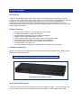
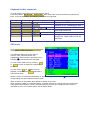
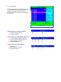
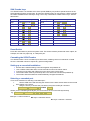
SCOUTcombo Installation guide Specifications Part Numbers 1013-108 8 port KVM Switch 1013-116 Cables & Accessories 2094-02PU USB & PS/2 Cable Set 1.8m 2094-03PU USB & PS/2 Cable Set 3.0m Package Contents 1013-108 9014-00A 5 v PSU Rackmount Brackets 16 port KVM Switch 2094-05PU USB & PS/2 Cable Set 5.0m 1013-116 9014-00A 5 v PSU Rackmount Brackets Physical Properties 8 Port 16 Port Height 4.5 cm 4.5 cm Width 44.0 cm 44.0 cm Operation and Storage parameters Operating Temperature: Storage Temperature: Humidity: Power Depth 15.7 cm 15.7 cm Unit Weight 1.90 kg 1.90 kg 0~50° C (32 to 122° F) -20~60° C (-4 to 140° F) 0~80% RH non-condensing Via External PSU. Resolution 2048 x 1536 @ 85Hz Selection Method Push button, Hot Key (PS/2 or USB Keyboards) and On Screen Display LED’s Red - PC selected. Green – PC on line. Connections Computer Ports Monitor Keyboard, Mouse Console Ports Monitor Keyboard Mouse 8 Port 8 sets: HD 15 pin Female USB & PS/2 signals combined 16 Port 16 sets: HD 15 pin Female USB & PS/2 signals combined 1 set: HD 15 pin Female 1 set: PS/2 6 pin mini DIN 1 set: USB A-type* 1 set: PS/2 6 pin mini DIN 1 set: USB A-type* 1 set: HD 15 pin Female 1 set: PS/2 6 pin mini DIN 1 set: USB A-type* 1 set: PS/2 6 pin mini DIN 1 set: USB A-type* * USB HID devices only © Copyright 2007. All rights reserved. Daxten, the Daxten logo, SCOUTcombo and The Brains Behind KVM Switching and Sharing are trademarks of Daxten Industries. All other trademarks acknowledged. Revision 1.0 SCOUTcombo Introduction Thank you for purchasing the SCOUTcombo Switch. This product will ensure easy and accurate control over 8 to 16 Servers through a single console. The SCOUTcombo is compatible with USB style computers. The SCOUTcombo supports high resolutions of up to 2048 x 1536 without any deterioration of the image quality. Switching between PCs can be accomplished in three ways: through keyboard Hot Key commands, the On Screen Display (OSD) or by using the convenient front panel PC selection buttons. Product Features Allows a user to control 8 – 16 computers from one console. No additional software is required for operation. Supports Monitor resolutions of up to 2048 x 1536 @ 85Hz. Supports VGA, SVGA and MultiSync monitors. Select via Push-button, Keyboard Hot Key control or Menu Driven OSD Comes with Auto-Scan mode for convenient automatic switching. Front panel status LEDs give a clear indication of the active PC. Rack Mountable in 19” Rack (1U). Tri-Level Cascade, allowing up to 4096 Servers to controlled from one console. Hardware Installation Before connecting your computers and console devices to the SCOUTcombo switch, please ensure that all devices are powered off. Note: USB keyboards with an integrated USB hub are not supported. Rear Panel Layout 164-Port switch Using the SCOUTcombo The SCOUTcombo provides three methods to select the desired computer. You may either use the Select button on the unit, use the keyboard Hot Key commands, or use the Menu Driven OSD. Keyboard Hot Key commands To send Hot Key commands to the SCOUTcombo switch, press and release Scroll Lock Scroll Lock within 5 seconds. Press a command key followed by Enter, for the desired effect. The following commands are supported: First Key Second Key Command Key Command Result Display‟s the OSD menu Switches to PC connected to port 1 Switches to the desired PC Auto-Scan mode ON Console Lock Changes Hot Key- Cycles through Scroll Lock, Caps Lock or Ctrl as Hot Keys. Scroll Lock Scroll Lock Enter Scroll Lock Scroll Lock 1 Enter Scroll Lock Scroll Lock 1 Scroll Lock Scroll Lock S Enter Scroll Lock Scroll Lock H Enter Scroll Lock Scroll Lock K Enter …… 16 Enter OSD menu Press Scroll Lock Scroll Lock will display the OSD‟s Main Menu Enter , this The OSD Main Menu shows the channel number, name, selected channel row (highlighted), Servers that are powered on and available (), Channels that are cascaded. You can exit the OSD menu by pressing Esc or Enter to leave the OSD to the selected server. You can use the and arrow keys to highlight a computer, and Enter will select it and leave the OSD. User OSD Where a server is connected and powered on, the following symbol will appear and the corresponding front panel indicator will turn green. When a channel is cascaded a will appear to the left of the name. When running the OSD on a cascaded switch, a number will appear in the top left corner of the OSD menu (below the KVM layer number), indicating the parent port. E.g. 8 indicates that the switch is cascaded on port 8. On a master switch this will remain blank. The Administrator OSD st nd rd 1. KVM Layer No – 1 , 2 or 3 . 2. Cascaded channel number. 3. PC Name – User defined name (31 Characters) 4. Page Up / Page Down indicator (16 Port unit only) 5. PC Status a Buzzer On b Buzzer Off L Locked Port Computer Powered On Channel Scan Function On 6. Current Channel Number F1: Set up: basic set up menu F2: Scan: autoscan function Administrator’s OSD F3: Lock: setup lock/unlock, and available when F5 Security is set „ON‟ F4: Rename: rename selected port name. F5: Security: security function and user priority setting F6: Lock Port: PC port lock function (administrator only) F1: - Setup Mode. Use the up / down arrow keys to move through the menu, and the left / right arrow keys to make changes. Scan Mode: Select - Scan through selected channels “S” as indicated on the main OSD menu in Status column. PC ON - Scan through all powered servers only. Scan Time: 5 seconds (default) to 90 seconds in 5 second increments. OSD Setup Banner Time: Sets the banner display time. – 5 seconds to 15 seconds in 5 second increments. Position: Menu - Allows you to set the position of the OSD menu, by using the arrow keys. Banner - Allows you to set the position of the channel banner, by using the arrow keys. Hotkey: Allows selection of Hot Keys. Choices are Scroll Lock , Caps Lock or Ctrl Note: Hot Keys can also be changed by the use of hot key command K. e.g.: If the hot key is set to Scroll Lock, then Scroll Lock Scroll Lock K make Caps Lock or Ctrl the hot key. Enter will Sound: Enable (ON) or disables (OFF) the internal buzzer. Language: Sets language of the OSD menu. Choices are: English (En), Deutsch (De) or Francais (Fr). F3: - Logout / Console Lock When the console is in locked mode, the push buttons and the console will lock. Pressing any key on the keyboard will present an unlock window. This will only accept the correct password. Note: If you forget your password, then there is no way in which to disable the security and the switch will need to be returned to Daxten. F4: - Rename. Allows you to rename the PC / Server name shown on the OSD menu and channel banner. F5: - Security Mode Entering the correct password enables the security function. Note: The Default settings are User Name: admin Password: 123456 After setting the security mode to ON, this automatically enables the Lock Mode (F3), and also allows the use of the Hot Key H command. This will lock the console and log the user off. Only the Administrator can unlock the console. Users will have access to servers for which they have rights to access. Security Setup User Authorisation Setting F6: - Lock Port This blocks all access to the locked server. An “L” with be displayed in the Status column of the OSD menu. The port can be unlocked by selecting F6 from the OSD menu and keying in the password. Port Lock Channel Banner (Single Switch) 1. Channel Number. (PC No). 2. PC name (Channel) Channel Banner (Cascaded Switches) 1. 2. 3. 4. st 1 Layer Channel Number. (PC No) nd 2 Layer Channel Number. (PC No). Channel Number. (PC No). PC name (Channel) Channel Banner (Scan Mode) 1. Scan Mode. 2. Channel Number. (PC No). 3. PC name (Channel) SUN Combo keys The SCOUTcombo can emulate some of the special SUN keys to perform special functions in the SUN Operating System environment. So when the SCOUTcombo is connected to a SUN computer, the switch emulates these SUN keys using a set of key combinations called Combo keys. See the table below. SUN key Stop Combo key Left key Left Alt SUN key Help Combo key Left key F11 Props Left key Left Ctrl Compose Left key Left Shift Front Left key F1 Mute Left key 1 Open Left key F2 Volume Down Left key 2 Find Left key F3 Volume Up Left key 3 Again Left key F4 Power Left key F12 Undo Left key F5 Copy Left key F6 Paste Left key F7 Cut Left key F8 Reset Switch Press the reset switch to perform a system reset. This switch must be pushed with a thin object, for example, the end of a paper clip, or a ball point pen. Cascading the SCOUTcombo The SCOUTcombo can be cascaded up to three levels, enabling control of a maximum of 4096 servers. Cascaded units don‟t require any special configuration. Setting up a cascaded installation: Ensure all the switches being connected together are powered off. Use a USB & PS/2 Cable Set to connect the slave units of the maser switch. Connect only the VGA and PS/2 ports on the slave units console ports. The master switch must be powered up first. The slave units can then be powered up. The master and slave switches will automatically configure themselves. Selecting a cascaded port. There a two methods for selecting a cascaded port:1. Use the OSD menu and selecting the channel for the slave switch and then the second slave switch or the server. 2. Using the hot key to access the port directly using the Hot Key D command. Scroll Lock Scroll Lock D number Enter Where you are cascading three layers you can access a server on the last layer directly e.g. Scroll Lock Scroll Lock D 2 D 5 D 7 Enter D2: layer 1 channel 2 links to D5: layer 2 channel 5 links to D7: layer 3 channel 7 selected Service Information Technical Support If you cannot determine the nature of a problem, please call Daxten and ask for Technical Support. If possible, call from a phone located near the unit, as we may be able to solve your problem directly over the phone. If we cannot solve your problem, and determine that the fault is in the unit, we will issue a Return Material Authorisation (RMA) number that must appear on the outside of all returned products. The unit should be double-packed in the original container, insured, and shipped to the address given to you by our Technical Support representative. The Technical Support offices are found on the back of this manual. Limited Warranty Daxten warrants to the end user that this product is and will be free from defects in materials and workmanship for a period of 24 months from the date of purchase. If during the warranty period the product should fail, the purchaser must promptly call Daxten for a RETURN MATERIALS AUTHORIZATION (RMA) number. Make sure that the RMA number appears on the packing slip, proof of purchase, AND ON THE OUTSIDE OF EACH SHIPPING CARTON. Unauthorized returns or collect shipments will be refused. Ship prepaid to the Daxten office (see back page) where you purchased your product. The above limited warranty is voided by occurrence of any of the following events, upon which the product is provided as is, with all faults, and with all disclaimers of warranty identified below: 1. 2. 3. 4. 5. 6. 7. If non-Daxten approved power supply or cabling is attached to the product. If defect or malfunction was caused by abuse, mishandling, unauthorized repair, or use other than intended. If unauthorized modifications were made to product. If unreported damages occurred in any shipment of the product. If damages were due to or caused by equipment or software not provided by Daxten. If the product is used with non-grounded or incorrectly polarized AC power. If the product is used in contradiction to any instruction provided by any User Guide or Instruction Sheet provided to you or with the product. EXCEPT AS SPECIFICALLY PROVIDED ABOVE AND TO THE MAXIMUM EXTENT ALLOWED BY LAW, DAXTEN DISCLAIMS ALL WARRANTIES AND CONDITIONS WHETHER EXPRESS, IMPLIED, OR STATUTORY AS TO ANY MATTER WHATSOEVER INCLUDING, WITHOUT LIMITATION, TITLE, NON-INFRINGEMENT, CONDITION, MERCHANTABILITY OR FITNESS FOR ANY PARTICULAR OR INTENDED PURPOSE. EXCEPT AS EXPRESSLY PROVIDED ABOVE AND TO THE MAXIMUM EXTENT ALLOWED BY LAW, DAXTEN SHALL NOT BE LIABLE FOR ANY SPECIAL, INDIRECT OR CONSEQUENTIAL DAMAGES (INCLUDING WITHOUT LIMITATION, LOSS OF PROFIT, LOSS OF BUSINESS, LOSS OF INFORMATION, FINANCIAL LOSS, PERSONAL INJURY, LOSS OF PRIVACY OR NEGLIGENCE) WHICH MAY BE CAUSED BY OR RELATED TO, DIRECTLY OR INDIRECTLY, THE USE OF A PRODUCT OR SERVICE, THE INABILITY TO USE A PRODUCT OR SERVICE, INADEQUACY OF A PRODUCT OR SERVICE FOR ANY PURPOSE OR USE THEREOF OR BY ANY DEFECT OR DEFICIENCY THEREIN EVEN IF DAXTEN OR AN AUTHORIZED DAXTEN DEALER HAS BEEN ADVISED OF THE POSSIBILITY OF SUCH DAMAGES OR LOSSES. Waste Electrical and Electronic Equipment (WEEE) Within the European Union, this symbol indicates that this product should not be disposed in household waste. It should be deposited at an appropriate facility to enable recovery and recycling. For information on how to recycle this product, please check with the reseller of the product that replaces this product "Take Back" or the original seller of this product. www.daxten.com Ireland Bay 21 Free Zone West Shannon, Co. Clare [email protected] www.daxten.ie Tel: +353 (0) 61 23 4000 Fax: +353 (0) 61 23 4099 • Österreich Tenschert Str. 8 A-1230 Wien [email protected] www.daxten.at Tel: +43 (0)1 879 77 65 Fax: +43 (0)1 879 77 65 30 Worldwide [email protected] www.daxten.eu • USA [email protected] www.daxten.us • Deutschland Salzufer 16, Geb. B 10587 Berlin [email protected] www.daxten.de Tel: +49 (0) 30 8595 37-0 Fax: +49 (0) 30 8595 37-99 United Kingdom 5 Manhattan Business Park Westgate London W5 1UP [email protected] www.daxten.co.uk Tel: +44 (0) 20 8991 6200 Fax: +44 (0) 20 8991 6299 • Schweiz Badenerstrasse 701 8048 Zürich [email protected] www.daxten.ch Tel: +41 (0) 43 321 73 93 Fax:+41 (0) 43 321 73 94 • • • España C/Florian Rey, 8 50002 Zaragoza [email protected] www.daxten.com.es Tel: +34 902 197 662 Fax: +34 976 201 633 Sweden [email protected] www.daxten.se France 44, rue du Général Leclerc 91230 Montgeron [email protected] www.daxten.fr Tel: +33 (01) 69 40 04 05 Fax:+33 (01) 69 03 75 19 • • • Denmark [email protected] www.daxten.dk •