1
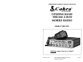
OPERATING INSTRUCTIONS FOR YOUR
40 CHANNEL
CITIZENS BAND
SSB/AM 2-WAY
MOBILE RADIO
Model 148 GTL
Nothing comes close to a Cobra™
PRINTED IN CHINA
©2002 COBRA ELECTRONICS CORPORATION
6500 WEST CORTLAND STREET
CHICAGO, IL 60707 USA
480-046-P
How To Use Your
Serial No.
Date of Purchase
Dealer Name
Keep this manual for detailed information
about your Cobra CB Radio System.
SAVE YOUR SALES RECEIPT, THE
CARTON AND “PACKING” FOR
POSSIBLE FUTURE USE.
40-CHANNEL,
CITIZENS BAND
SSB/AM 2-WAY MOBILE RADIO
Model 148 GTL
Contents
Page
Section I: Introduction ..........................................................................................2
Section II: Specifications ....................................................................................3, 4
Section III: Installation ..............................................................................5, 6, 7, 8
Section IV: Operation........................................................................................9-17
Controls and Indicators ..........................................................................................9
A.Control Functions....................................................................................9, 10, 11
The Cobra® line of quality products includes:
B.Indicator Functions ............................................................................................12
Operating Procedure to Receive ..........................................................................12
CB radios
Operating Procedure to Transmit ..........................................................................13
®
microTALK radios
Receiving SSB Signals ....................................................................................13, 14
Radar/Laser Detectors
Alternate Microphones and Installation ....................................................15, 16, 17
GPS
Section V: Maintenance and Adjustment ........................................................18-21
®
Safety Alert
Traffic Warning Systems
Accessories
HighGear™ Accessories
If You Think You Need Service,
please contact your local dealer.
Section VI: Appendix ................................................................................19, 20, 21
Ten Code ..............................................................................................................19
A few Rules That Should Be Obeyed ....................................................................20
How Your CB Can Serve You ................................................................................20
Use Channel 9 for Emergency Messages Only ......................................................21
Section I Introduction
Section II Specifications
FREQUENCY RANGE
The COBRA 148GTL transceiver represents one of the most advanced SSB/AM
two-way radios ever designed for use as a Class D station in the Citizens Radio
Service. This unit features advanced Phase Lock Loop (PLL) circuitry, which is used
in the AM mode and in the upper and lower single sideband modes, providing
complete coverage of all 40 channels shown below.
Channel
Channel Frequency
in MHz
Channel
Channel Frequency
in MHz
GENERAL
Channels
Frequency Range
Frequency Control
Frequency Tolerance
Frequency Stability
Operating Temperature Range
Microphone
1
2
3
4
5
26.965
26.975
26.985
27.005
27.015
21
22
23
24
25
27.215
27.225
27.255
27.235
27.245
6
7
8
9
10
27.025
27.035
27.055
27.065
27.075
26
27
28
29
30
27.265
27.275
27.285
27.295
27.305
11
12
13
14
15
27.085
27.105
27.115
27.125
27.135
31
32
33
34
35
27.315
27.325
27.335
27.345
27.355
Weight
Antenna Conductor
Semiconductors
16
17
18
19
20
27.155
27.165
27.175
27.185
27.205
36
37
38
39
40
27.365
27.375
27.385
27.395
27.405
Meter (3-in-1)
The COBRA 148GTL has a vastly superior receiver which includes an RF gain
control and noise blanker circuitry effective in both AM and SSB modes., and an
automatic noise limiter effective in the AM mode. The receiver also features
increased protection against cross modulation and strong adjacent channel signals.
To obtain maximum performance please read carefully the descriptions and
operating instructions in this manual.
2
Input Voltage
Current Drain
Size
40 AM, 40 LSB, 40 USB.
26.965 to 27.405 MHz.
Phase Lock Loop (PLL) synthesizer.
0.005%.
0.001%.
-22° F to +122° F (-30° C to +50° C).
Plug-in dynamic; with push-to-talk switch and
coiled cord.
13.8V DC nominal, 15.9V max., 11.7V min.
(positive or negative ground).
Transmit: AM full mod., 2.2A. SSB 12 watts PEP
output, 2A.
Receive: Squelched, 0.25A Maximum audio
output, 0.6A.
2 3/8”(H) x 7 7/8”(W) x 9 1/4”(D).
(6 cm (H) x 20 cm (W) x 23.5 cm (D)).
5 lbs. (2.27 kg).
UHF, S0239.
3 field effect transistors, 45 transistors, 63 diodes,
6 integrated circuits, 1 two color light emitting
diode.
Illuminated; indicates relative output power,
received signal strength, and SWR.
TRANSMITTER
Power Output
Modulation
Intermodulation Distortion
SSB Carrier Suppression
Unwanted Sideband
Frequency Response
Output Impedance
Output Indicators
AM, 4 watts. SSB, 12 watts, PEP.
High-and low-level Class B, Amplitude
Modulation.
SSB: 3rd order, more than -25 dB. 5th order,
more than -35 dB.
55 dB.
50 dB.
AM and SSB; 300 to 2500 Hz.
50 ohms, unbalanced.
Meter shows relative RF output power and SWR.
Transmit LED glows red when transmitter is in
operation.
3
Section II Specifications (Cont.)
Section III Installation
LOCATION
RECEIVER
Sensitivity
SSB: 0.25 µV for 10dB (S+N)/N at greater than
1/2-watt of audio output.
AM: 0.5 µV for 10 dB (S+N)/ at greater than 1/2watt of audio output.
Selectivity
AM: 6dB @ 3 KHz, 50 dB @ 9 KHz.
SSB: 6 dB @ 1.1 KHz, 60 dB @ 2.3 KHz.
Image Rejection
More than 65 dB.
IF Frequency
AM: 7.8 MHz 1st IF, 455 KHz 2nd IF.
SSB: 7.8 MHz.
Adjacent-Channel Rejection
60 dB AM & 70 dB SSB.
AM and SSB RF Gain Control
40 dB adjustable for optimum signal reception.
Automatic Gain Control (AGC)
Less than 10 dB change in audio output for
inputs from 10 to 100,000 microvolts.
Squelch
Adjustable; threshold less than 0.25 µV.
ANL
Switchable.
Noise Blanker
RF type, effective on AM and SSB.
Voice Lock Range
±2.5 KHz.
Audio Output Power
4 watts into 8 ohms.
Frequency Response
300 to 2500 Hz.
Built-in Speaker
4 ohms, round.
External Speaker (Not Supplied)
8 ohms; disables internal speaker when
connected.
Plan the location of the transceiver and microphone bracket before starting the
installation. Select a location that is convenient for operation and does not
interfere with the driver or passengers in the vehicle. In automobiles, the
transceiver is usually mounted below the dash panel, with the microphone
bracket beside it.
MOUNTING THE CONNECTION
The COBRA 148GTL is supplied with a universal mounting bracket. When
mounting the bracket and radio to your car, make sure it is mechanically strong.
Also provide a good electrical connection to the chassis of the vehicle. Proceed as
follows to mount the transceiver:
1. After you have determined the most convenient location in your vehicle, hold
the COBRA 148GTL with mounting bracket in the exact location desired. If
nothing will interfere with mounting it in the desired position, remove the
mounting bolts. Before drilling the holes, make sure nothing will interfere with
the installation of the mounting bolts.
2. Connect the antenna cable plug to the standard receptacle on the rear panel.
Most CB antennas are terminated with a type PL-259 plug and mate with the
receptacle.
3. Connect the red DC power input wire (with the fuse) to +13.8V DC. This wire
extends from the rear panel. In automobile installation, +13.8V DC is usually
obtained from the accessory contact on the ignition switch. This prevents the
set being left on accidentally when the driver leaves the car and also permits
operating the unit without the engine running. Locate the accessory contact on
most ignition switches by tracing the power wire from the AM broadcast
receiver in the car.
4. Connect the black lead to -13.8V DC. This is usually the chassis of the car. Any
convenient location with good electrical contact (remove paint) may be used.
PA SYSTEM
Power Output
4 watts into external speaker.
External Speaker for PA
(Not Supplied)
8 ohms.
5. Mount the microphone bracket on either side of the transceiver, using the two
screws supplied. When mounting in an automobile, place the bracket under
the dash so the microphone is readily accessible.
(SPECIFICATIONS SUBJECT TO CHANGE WITHOUT NOTICE)
4
5
Section III Installation (Continued)
Section III Installation (Continued)
IGNITION NOISE INTERFERENCE
TUNING THE ANTENNA FOR OPTIMUM SWR
Use of a mobile receiver at low signal levels is normally limited by the presence
of electrical noise. The primary source of noise in automobile installations is from
the generator and ignition system in the vehicle. Under most operating conditions,
when signal level is adequate, the background noise does not present a serious
problem. Also, when extremely low level signals are being received, the
transceiver may be operated with vehicle engine turned off. The unit requires very
little current and therefore will not significantly discharge the vehicle battery.
Even though the COBRA 148GTL has ANL and NB controls, in some installations
ignition interference may be high enough to make good communications
impossible. The electrical noise may come from several sources. Many possibilities
exist and variations between vehicles require different solutions to reduce the
noise. Consult your COBRA dealer or a 2-way radio technician for help in
locating and correcting the source of severe noise.
Since there is such a wide variety of base and mobile antennas, this section will
strictly concern itself to the various types of mobile adjustable antennas.
Because antenna length is directly related to the channel frequency, it must be
tuned to resonate optimally all 40 channels of the transceiver. Channel 1 requires
a longer antenna than Channel 40 because it is a lower frequency.
Due to the various methods of adjusting antennas for proper SWR we have chosen
what we think is the optimum method:
ANTENNA
Since the maximum allowable power output of the transmitter is limited by the
FCC, the antenna is one important factor affecting transmission distance. Only a
properly matched antenna system will allow maximum power transfer from the
50 ohm transmission line to the radiating element. In mobile installations (cars,
trucks, boats, etc.), an antenna system that is non-directional should be used.
A vertically polarized, quarter-wavelength whip antenna provides the most reliable
operation and greatest range. Shorter, loaded-type whip antennas are more
attractive, compact and adequate for applications where the maximum possible
distance is not required. Also, the loaded whips do not present the problems of
height imposed by a full quarter-wavelength whip.
Mobile whip antennas utilize the metal body of the vehicle as a ground plane.
When mounted at a corner of the vehicle they are slightly directional, in the
direction of the body of the vehicle. For all practical purposes, however, the
radiation pattern is nondirectional. The slight directional characteristic will be
observed only at extreme distances. A standard antenna connector (type SO239)
is provided on the transceiver for easy connection to a standard PL 259 cable
termination.
If the transceiver is not mounted on a metal surface, it is necessary to run a
separate ground wire from the unit to a good metal electrical ground in the
vehicle. When installed in a boat, the transceiver will not operate at maximum
efficiency without a ground plate, unless the vessel has a steel hull.
Before installing the transceiver in a boat, consult your dealer for information
regarding an adequate grounding system and prevention of electrolysis between
fittings in the hull and water.
6
A. Antennas with adjustable screws (set screws)
1. Start with the antenna extended and tighten the set screw lightly enough so
that the antenna can be lightly tapped with your finger for easy adjustment.
2. Set your COBRA 148GTL to Channel 21. Press the PTT (Push-to-Talk)
switch, and tap the antenna (making it shorter). The SWR meter will show a
lower reading each time the antenna is tapped. By continuing to shorten
the antenna you will notice the SWR reading will reach a low point and
then start rising again. This means that you have passed the optimum point
for Channel 21. Extend the antenna a short distance and again follow the
procedure above.
When the lowest point has been reached, switch to Channel 1 and then to
Channel 40 and compare SWR readings. They should be almost equal.
B. Antennas which must be cut to proper length
1. Follow the same procedure as above, but adjust the length by cutting in
1/8” increments until a good match is obtained.
2. Be very careful not to cut too much at one time, as once it is cut, it can no
longer be lengthed.
3. The whip is easily cut by filing a notch all the way around and breaking the
piece off with a pliers.
NOTE
THE PROPER SETTING IS ACHIEVED WHEN THE SWR IS
1.5 OR BELOW, AND WHEN IT HAS THE SAME READING
FOR CHANNELS 1 AND 40.
If you are having difficulties in adjusting your antenna, check the following:
A. All doors must be closed when adjusting the antenna.
B. Make sure the antenna base is grounded.
C. Check your coaxial cable routing (it may be pinched when routed into the car).
7
Section III Installation (Continued)
D. Try a different location on your car (keeping in mind the radiation pattern
you wish).
E. Is the antenna perfectly vertical?
F. Try a different location in your neighborhood. Stay away from large metal
objects when adjusting (metal telephone or light posts, fences, etc.).
Section IV Operation
CONTROLS AND INDICATORS
There are thirteen controls and three indicators on the front panel of your
COBRA 148GTL.
NOTE
The COBRA 148GTL will operate into an SWR of 2 to 1 indefinitely
and sustain an SWR of 20:1 for a maximum of 5 minutes at rated
operating conditions.
EXTERNAL SPEAKER
The external speaker jack (EXT SPK) on the rear panel is used for remote receiver
monitoring. The external speaker should have 8 ohms impedance and be able to
handle at least 4 watts. When the external speaker is plugged in, the internal
speaker is disconnected.
PUBLIC ADDRESS
To use the transceiver as a public address system connect an external 8 ohm
speaker (4 watts minimum) to the PA SPK jack located on the rear panel. Direct
speaker away from the microphone to prevent acoustic feedback. Physical
separation or isolation of the microphone and speaker is important when operating
the PA at high output levels.
A. CONTROL FUNCTIONS
1. OFF/ON/VOLUME (inner dual concentric). Turn clockwise to apply power to
the unit and to set the desired listening level. During normal CB operation,
the Volume control is used to adjust the output level obtained either at the
transceiver speaker or the external speaker, if used.
2. SQUELCH (outer dual concentric). This control is used to cut off or eliminate
receiver background noise in the absence of an incoming signal. For
maximum receiver sensitivity it is desired that the control be adjusted only to
the point where the receiver background noise or ambient background noise
is eliminated. Turn fully counterclockwise then slowly clockwise until the
receiver noise disappears. Any signal to be received must now be slightly
stronger than the average received noise. Further clockwise rotation will
increase the threshold level which a signal must overcome in order to be
heard. Only strong signals will be heard at a maximum clockwise setting.
3. RF GAIN CONTROL (inner dual concentric). Used to reduce the gain of the
RF amplifier under strong signal conditions.
8
9
Section IV Operation (Continued)
Section IV Operation (Continued)
4.
SWR CAL CONTROL (outer dual concentric). In order for you to achieve
maximum radiated power and the longest range, it is important that your
antenna be in good condition, properly adjusted and matched to your
transceiver. The Built-in SWR (standing wave ratio) meter lets you easily
measure your antenna condition. To operate this function, connect your
antenna to the transceiver antenna output connector. Select a channel near
the middle of the band such as 21 or the channel you plan to use most
frequently. Turn the power on and set the meter function switch to the CAL
position. Press and hold the microphone push-to-talk button and using the
SWR CAL control, adjust the meter to read the CAL position indicated on the
meter face. Then, without releasing the microphone button, switch the meter
function switch to the SWR position and read the SWR indicated. The lower
the figure, the better, with 1 being ideal. Generally speaking, readings up to
3 are acceptable, but over 3 indicates that you are losing radiated power and
antenna adjustment may be advisable.
5.
DYNAMIKE. Adjusts the microphone gain in the transmit and PA modes. This
controls the gain to the extent that full talk power is available several inches
away from the microphone. In the Public Address (PA) mode the control
functions as the volume control.
10. PA/CB SWITCH. Selects the mode of operation. In the CB position, the PA
function is disabled and the unit will transmit and receive on the speaker that is
connected. In the PA mode, incoming CB transmission will be heard through the
PA speaker. This allows you to monitor messages while outside of your vehicle.
To use the PA feature, a speaker having a voice coil impedance of 8 ohms and
a power handling capability of at least three watts should be used. This speaker
must be plugged into the PA SPKR jack at the rear of the transceiver. If the
public address feature is to be used primarily for outdoor applications, the use
of a weatherproof horn type public address speaker is recommended. The
durability of this type speaker plus the inherent efficiency of such a speaker
will provide more than adequate results when combined with the high audio
output level available from the COBRA 148GTL. With the PA speaker
connected as outlined previously, be sure that there is physical separation
between the microphone and the speaker itself. If the speaker is located too
close to the microphone, acoustic feedback will result when the public address
system is operated at high volume. A directional type outdoor speaker reduces
the amount of isolation required. Some experimentation will determine the
minimum amount of isolation required for a given sound level from the public
address system.
6.
7.
8.
9.
VOICE LOCK. Allows variation of the receiver operating frequencies above
and below the assigned frequency. Although this control is intended
primarily to tune in SSB signals, it may also be used to optimize AM signals
as described in the Operating Procedure paragraphs.
DIM/NOR/BRT SWITCH. Controls the brightness of the meter and LED
channel indicator for optimum intensity for day or night-time driving.
CHANNEL SELECTOR. This switch selects any one of the forty Citizens Band
channels desired. The selected channel appears on the LED readout directly
above the Channel Selector knob. Channel 9 has been reserved by the FCC
for emergency communications involving the immediate safety of life of
individuals or immediate protection of property. Channel 9 may also be used
to render assistance to a motorist.
0FF/ANL/NB + ANL SWITCH. In the ANL position only the automatic
noise limiter in the audio circuits is activated. When the switch is placed
in the ANL + NB position, the RF noise blanker also is activated. The
RF noise blanker is very effective for repetitive impulse noise such as
ignition interference.
10
NOTE
PA volume is controlled by adjusting the DYNAMIKE knob to
the desired volume.
11. S-RF/CAL/SWR SWITCH. When in the S-RF position, the meter swings
proportionally to the strength of the received signal. When transmitting, the
meter indicates relative RF output power.
When in the “CAL” position, the SWR meter can be calibrated by adjusting the
“SWR” control to the “CAL” mark on the meter face.
When in “SWR” position, the standing wave ratio is measured.
12. MODE (LSB/AM/USB) SWITCH. This switch is used to select AM, LSB or USB
mode of operation. Unless the station with which communication is desired is
equipped with SSB, the AM mode is normally used. The mode selector switch
changes the mode of operation of both transmitter and receiver simultaneously.
Turn to “Receiving SSB signals” for a further explanation of single sideband.
13. TONE SWITCH-HI/NOR/LOW. This switch is used to shape the audio
response to the operator’s preference. Bass is increased in the LOW position
and treble is increased in the HI position.
11
Section IV Operation (Continued)
Section IV Operation (Continued)
B. INDICATOR FUNCTIONS
7. Set the CHANNEL selector switch to the desired channel.
1. S-METER. Swings proportionally to the strength of the incoming signal.
8. Adjust the VOICE LOCK control to clarify the SSB signals or to optimize
AM signals.
2. RF METER. Swings proportionally to the RF output power.
3. SWR METER. Swings proportionally to the ratio of standing wave voltage and RF
output. Used to properly adjusts the length of the antenna, and to monitor the
quality of the coaxial cable and all RF electrical connections. If there is any
degradation whatsoever in any of the above, due to humidity, salt, spray, vibration or
corrosion, the SWR meter reading will rise, thereby indicating that a problem exists.
To calibrate, switch to the “CAL” position, transmit in AM Mode by pressing the (PTT)
mic switch, and adjust the SWR control to the “CAL” mark on the meter then switch to
“SWR” position for the SWR measurement (Note: CB must be in AM mode).
4. CHANNEL INDICATOR. Numbered LED indicates the selected channel you
wish to operate on.
5. RECEIVE/TRANSMIT INDICATOR. The receiver/transmit LED indicator is
located next to the channel indicator. When in receive, the LED will be green.
When in transmit the LED will be red.
6. PRESS-TO-TALK MICROPHONE. The receiver and transmitter are controlled
by the Press-To-Talk switch on the microphone. Press the switch and the
transmitter is activated, release the switch to receive. When transmitting, hold
the microphone two inches from the mouth and speak clearly in a normal
“voice”. The radio comes complete with low-impedance (500 ohm) dynamic
microphone. For installation instructions on the other microphones see
ALTERNATE MICROPHONES AND INSTALLATION section.
OPERATING PROCEDURE TO RECEIVE
1. Be sure that the power source, microphone and antenna are connected to the
proper connectors before going to the next step.
2. Set PA-CB Switch to the CB position and turn unit on by turning VOL control
clockwise on COBRA 148GTL.
3. Set the VOLUME for a comfortable listening level.
4. Set MODE switch to the desired mode.
5. Set the RF gain control fully clockwise for maximum RF gain.
6. Listen to the background noise from the speaker. Turn the SQUELCH control
slowly clockwise until the noise JUST disappears (no signal should be present).
Leave the control at this setting. The SQUELCH is now properly adjusted. The
receiver will remain quiet until a signal is actually received. Do not advance
the control too far, or some of the weaker signals will not be heard.
12
OPERATING PROCEDURE TO TRANSMIT
1.
Select the desired channel of transmission.
2.
Set the DYNAMIKE control fully clockwise.
3.
If the channel is clear, depress the Push-To-Talk switch on the microphone
and speak in a normal voice.
RECEIVING SSB SIGNALS
There are three types of signals presently used for communications in the Citizens
Band: AM, USB, and LSB. When the MODE switch on your unit is placed in the
AM position, only standard double-sideband, full carrier signals will be detected.
An SSB signal may be recognized while in the AM mode by its characteristic
“Donald Duck” sound and the inability of the AM detector to produce an
intelligible output. The USB and LSB modes will detect upper sideband and lower
sideband respectively, and standard AM signals.
SSB reception differs from standard AM reception in that SSB receiver does not
require a carrier or opposite sideband to produce an intelligible signal. A singlesideband transmitted signal consists only of the upper or the lower sideband and
no carrier is transmitted. The elimination of the carrier from the AM signal helps to
eliminate the biggest cause of whistles and tones heard on channels which make
even moderately strong AM signals unreadable. Also, SSB takes only half of an
AM channel, therefore two SSB conversations will fit into each channel expanding
the 40 AM channels to 80 SSB channels. The reduction in channel space required
also helps in the receiver because only half of the noise and interference can be
received with 100% of the SSB signal.
An SSB signal may be received only when the listening receiver is functioning in
the same mode. In other words, an upper sideband signal (USB) may be made
intelligible only if the receiver is functioning in the USB position.
If a lower sideband (LSB) signal is heard when the receiver is in the USB mode,
no amount of tuning will make the signal intelligible. The reason for this may be
understood if you consider that when the modulation is applied to the
transmitter’s microphone in the USB mode, the transmitter’s output frequency is
increased whereas in the LSB mode the transmitter’s output frequency is decreased.
The result in listening to the receiver is that when the MODE switch is in the
proper position (either USB or LSB), a true reproduction of single tone of
modulation will result, and if the tone is increased in frequency (such as a low-
13
Section IV Operation (Continued)
pitched whistle or a high-pitched whistle) you will hear the increase in the output
tone of the receiver. If the incorrect mode is selected, an increase in tone of a
whistle applied to the transmitter will cause a decrease in the resultant tone from
the receiver.
Thus when a voice is used in place of a whistle or tone, in the proper listening
mode the voice will be received correctly whereas in the incorrect mode, the
voice will be translated backwards and cannot be made intelligible by the voice
lock control. When listening to an AM transmission, a correct sideband is heard
in either mode since both upper and lower sideband are received.
Section IV Operation (Continued)
ALTERNATE MICROPHONES AND INSTALLATION
For best results, the user should select a low-impedance dynamic type microphone
or a transistorized microphone. Transistorized type microphones have a low output
impedance characteristic. The microphones must be provided with a 4-lead cable.
The audio conductor and its shielded lead comprise two of the leads. The third
lead is for receive control, the forth is for transmit control.
The microphone should provide the functions shown in schematic below:
4 WIRE MIC CABLE
Pin Number
Once the desired SSB mode has been selected, frequency adjustment may be
necessary in order to make the incoming signal intelligible, the VOICE LOCK
control allows the operator to vary frequency above and below the exact-center
frequency of the received signal. If the sound of the incoming signal is high or
low pitched, adjust the operation of the VOICE LOCK. Consider it as performing
the same function as a phonograph speed control. When the speed is set too
high, voices will be high-pitched and if set too low, voices will be low-pitched.
Also, there is only one correct speed that will make a particular record produce
the same sound that was recorded. If the record is played on a turntable that
rotates in the wrong direction (opposite sideband) no amount of speed control
(VOICE LOCK) will produce an intelligible sound.
Mic Cable Lead
1
2
3
4
An AM signal received while listening in one of the SSB modes will produce a
steady tone (carrier) in addition to the intelligence, unless the SSB receiver is
tuned to exactly the same frequency by the VOICE LOCK control. For simplicity it
is recommended that the AM modes be used to listen to AM signals.
Grounding
Audio Lead
Transmit Control
Receive Control
Fig. 1. Cobra 148GTL microphone schematic.
If the microphone to be used is provided with pre-cut leads, they must be revised
as follows:
1.
Cut leads so that they extend 7/16” (11 mm) beyond the plastic insulating
jacket of the microphone cable (see Fig. 2.)
2.
All leads should be cut to the same length. Strip the ends of each wire 1/8”
(2 mm) and tin the exposed wire.
Before beginning the actual wiring, read carefully, the circuit and wiring
information provided with the microphone you select. Use the minimum heat
required in soldering the connections. Keep the exposed wire lengths to a
minimum to avoid shorting when the microphone plug is reassembled.
14
15
Section IV Operation (Continued)
Section IV Operation (Continued)
3
Fig. 2. Microphone Cable Preparation.
To wire the microphone cable to the plug provided, proceed as follows:
3
4
2
1
2
4
1
Fig. 4. Microphone plug pin numbers viewed from rear of pin receptacle.
Be sure that the housing and the knurled ring of Fig. 3 are pushed back onto the
microphone cable before starting to solder. If the washer is not captive to the pin
receptacle body, make sure that it is placed on the threaded portion of the pin
receptacle body before soldering.
If the microphone jack is used to hold the pin receptacle during soldering
operation, best results are obtained when the connections to pins 1 and 3 are
made first and then the connections to pins 2 and 4. Use a minimum amount of
solder and be careful to prevent excessive solder accumulation on pins, which
could cause a short between the pin and the microphone plug housing.
Fig. 3. Microphone plug wiring.
1.
Remove the retaining screw.
2.
Unscrew the housing from the pin receptacle body.
3.
Loosen the two cable clamp retainer screws.
4.
Feed the microphone cable through the housing, knurled ring and washer as
shown Fig. 3B.
5.
The wires must now be soldered to the pins as indicated in the above wiring
tables. If a vise or clamping tool is available it should be used to hold the pin
receptacle body during the soldering operation, so that both hands are free to
perform the soldering. If a vise or clamping tool is not available, the pin
receptacle body can be held in a stationary position by inserting it into the
microphone jack on the front panel. The numbers of the pins of the microphone
plug are shown in Fig 4, as viewed from the back of the plug. Before soldering
the wire to the pins, pre-tin the wire receptacle of each pin of the plug.
Section IV Operation
(Continued)
16
6.
When all soldering connections to the pins of the microphone are complete,
push the knurled ring and the housing forward and screw the housing onto
the threaded portion of the pin receptacle body. Note the location of the
screw clearance hole in the plug housing with respect to the threaded hole
in the pin receptacle body. When the housing is completely threaded into
the pin receptacle body, a final fraction of a turn either clockwise or
counterclockwise may be required to align the screw hole with the threaded
hole in the pin receptacle body. When these are aligned, the retaining screw
is then screwed into place to secure the housing to the pin receptacle body.
7.
The two cable clamp retainer screws should now be tightened to secure the
housing to the microphone cord. If the cutting directions have been carefully
followed, the cable clamp should secure to the insulation jacket of the
microphone cable.
8.
Upon completion of the microphone plug wiring, connect and secure the
microphone plug in the transceiver.
17
Section V Maintenance and Adjustment
The COBRA 148GTL transceiver is specifically designed for the environment
encountered in mobile installations. The use of all solid state circuitry and its light
weight result in high reliability. Should a failure occur, however, replace parts
only with identical parts. Do not substitute. Refer to the schematic diagram and
parts list.
NOTE
If the performance described in the OPERATION and MAINTENANCE
AND ADJUSTMENT sections is not obtained, review the operating
instructions to insure that proper procedures were followed. If a problem
still exists, please contact your local dealer.
Section VI Appendix
Citizens Band radio operators have largely adopted the “10-code” for standard
questions and answers. Its use permits faster communications and better
understanding in noisy areas. The following table lists some of the more
common codes and their meanings:
10-CODE
Code
10-1
10-2
10-3
10-4
10-5
10-6
10-7
10-8
10-9
10-10
10-11
10-12
10-13
10-16
10-17
10-18
10-19
10-20
10-21
10-22
10-23
10-24
10-25
10-26
10-27
10-28
10-29
10-30
10-32
10-33
10-34
10-35
10-36
18
Meaning
Receiving poorly
Receiving well
Stop transmitting
OK, message received
Relay message
Busy, stand by
Out of service, leaving air
In service, subject to call
Repeat message
Transmission completed,
standing by
Talking too rapidly
Visitors present
Advise Weather/Road conditions
Make pick up at
Urgent business
Anything for us?
Nothing for you, return to base
My location is
Call by telephone
Report in person to
Stand by
Completed last assignment
Can you contact
Disregard last information
I am moving to channel
Identify your station
Time is up for contact
Does not conform to FCC rules
I will give you a radio check
EMERGENCY TRAFFIC
Trouble at this station
Confidential information
Correct time is
19
Code Meaning
10-37 Wrecker needed at
10-38 Ambulance needed at
10-39 Your message delivered
10-41 Please turn to channel
10-42 Traffic accident at
10-43 Traffic Tie up at
10-44 I have a message for you
10-45 All units within range
please report
10-50 Break channel
10-60 What is the next message
number?
10-62 Unable to copy, use
phone
10-63 Net directed to
10-64 Net clear
10-65 Awaiting your next
message/assignment
10-67 All units copy
10-70 Fire at
10-71 Proceed with transmission
in sequence
10-77 Negative contact
10-81 Reserve hotel room for
10-82 Reserve room for
10-84 My telephone number is
10-85 My address is
10-91 Talk closer to mike
10-93 Check my frequency on
this channel
10-94 Please give me a long
count
10-99 Mission completed, all
units secure
10-200 Police needed at
Section VI Appendix (Continued)
Section VI Appendix (Continued)
A FEW RULES THAT SHOULD BE OBEYED
1.
You are not allowed to carry on a conversation with another station for more
than five minutes at a time without taking a one-minute break, to give others
a chance to use the channel.
2.
You are not allowed to blast others off the air by over-powering them with
illegally amplified transmitter power, or illegally high antennas.
USE CHANNEL 9 FOR EMERGENCY MESSAGES ONLY
FCC gives the following examples of permitted and prohibited types of
communications for use on Channel 9. These are guidelines and are not
intended to be all-inclusive:
Permitted
Example Message
3.
You can’t use the CB to promote illegal activities.
Yes
”A tornado sighted six miles (10 km) north of town.”
4.
You are not allowed to use profanity.
No
”This is observation post number 10. No tornado sighted.”
5.
You may not play music in your CB.
Yes
”I am out of gas on Interstate 95.”
6.
You may not use your CB to sell merchandise or professional service.
No
”I am out of gas in my driveway.”
Yes
There is a four-car collision at Exit 10 on the Beltway, send
police and ambulance.”
No
”Traffic is moving smoothly on the Beltway.”
Yes
”Base to Unit 1, the Weather Bureau has just issued a
thunder storm warning. Bring the sailboat into port.”
No
”Attention all motorists. The Weather Bureau advises that the
snow tomorrow will accumulate 4 to 6 inches (10 to
15 cm).”
Yes
“There is a fire in the building on the corner of 6th and
Main Streets.”
No
“This is Halloween patrol unit number 3. Everything is
quiet here.“
HOW YOUR CB CAN SERVE YOU
•
•
•
•
•
•
•
•
•
Warn of traffic tie ups ahead.
Provide weather and road information.
Provide help fast in event of emergency or breakdown.
Suggest good spots to eat and sleep.
Make long trips more interesting, and help keep you awake.
Provide direct contact with your office or home.
Make friends for you as you travel.
Provide “local information” to find your destination.
Help law enforcement officers by reporting drunk and reckless drivers.
20
21
INSTRUCCIONES DE USO DEL
40 CANALES
RADIO BIDIRECCIONAL
MÓVIL SSB/AM DE
BANDA CIUDADANA
Modelo 148 GTL
Nada se compara a Cobra™
IMPRESO EN CHINA
©2002 COBRA ELECTRONICS CORPORATION
6500 WEST CORTLAND STREET
CHICAGO, IL 60707 USA
480-046-P
Instrucciones de uso del
Número de serie
Fecha de compra
Nombre del distribuidor
Conserve este manual como referencia detallada
de su sistema de radio CB Cobra.
GUARDE EL COMPROBANTE DE VENTA,
LA CAJA Y LOS MATERIALES DE EMBALAJE,
YA QUE POSIBLEMENTE TENGA QUE
UTILIZARLOS EN EL FUTURO.
RADIO BIDIRECCIONAL
MÓVIL SSB/AM DE 40 CANALES
DE BANDA CIUDADANA
Modelo 148 GTL
Índice
Página
Sección I: Introducción ................................................................................................2
Sección II: Especificaciones ......................................................................................3, 4
Sección III: Instalación ....................................................................................5, 6, 7, 8
Sección IV: Operación ............................................................................................9-17
Controles e indicadores ................................................................................................9
A. Funciones de control ....................................................................................9, 10, 11
La línea de productos de calidad Cobra® también incluye:
B. Funciones de los indicadores ..................................................................................12
Procedimiento operativo para recibir ..........................................................................12
Radios de banda civil (CB)
Procedimiento operativo para transmitir ......................................................................13
Radios microTALK®
Recepción de señales SSB ....................................................................................13, 14
Detectores de radar y láser
Micrófonos alternativos e instalación ..............................................................15, 16, 17
Sistemas GPS
Sistemas de advertencia de tráfico
Safety Alert®
Accesorios
Accesorios HighGear™
Si cree que requiere servicio,
comuníquese con un distribuidor de su localidad.
Sección V: Mantenimiento y ajustes ......................................................................18-21
Sección VI: Apéndice ......................................................................................19, 20, 21
Código 10....................................................................................................................19
Reglas que debe obedecer ..........................................................................................20
Aplicaciones del radio CB ..........................................................................................20
Utilice el canal 9 únicamente para mensajes de emergencia ......................................21
Sección I Introducción
Sección II Especificaciones
INTERVALO DE FRECUENCIAS
GENERALES
El transmisor-receptor COBRA 148GTL es uno de los radios transmisores-receptores
SSB/AM más avanzados que se han diseñado para usarse como estación de clase D
en el servicio de radio ciudadana. Esta unidad tiene avanzados circuitos de sincronización de fase (PLL, Phase Lock Loop), que se utilizan en la modalidad AM y en las
modalidades de banda lateral única (SSB) superior e inferior, permitiendo una cobertura
completa de los 40 canales de la banda ciudadana que se indican a continuación.
Canales
Intervalo de frecuencias
Control de frecuencia
Tolerancia de frecuencia
Estabilidad de frecuencia
Temperatura operativa
Micrófono
Canal
Frecuencia del canal
en MHz
Canal
Frecuencia del canal
en MHz
1
2
3
4
5
26,965
26,975
26,985
27,005
27,015
21
22
23
24
25
27,215
27,225
27,255
27,235
27,245
6
7
8
9
10
27,025
27,035
27,055
27,065
27,075
26
27
28
29
30
27,265
27,275
27,285
27,295
27,305
11
12
13
14
15
27,085
27,105
27,115
27,125
27,135
31
32
33
34
35
27,315
27,325
27,335
27,345
27,355
16
17
18
19
20
27,155
27,165
27,175
27,185
27,205
36
37
38
39
40
27,365
27,375
27,385
27,395
27,405
Voltaje de entrada
Consumo de corriente
Tamaño
Peso
Conductor de antena
Semiconductores
Medidor (3 en 1)
TRANSMISOR
Potencia de salida
Modulación
Distorsión por intermodulación
El radio COBRA 148GTL tiene un receptor ampliamente superior, con control de
ganancia de RF, un circuito de cancelación de ruido para las modalidades AM y SSB y
un limitador automático de ruido para la modalidad AM. El receptor también tiene
mayor protección contra modulación cruzada y señales fuertes de canales adyacentes.
Para obtener el mejor rendimiento, sírvase leer detenidamente las descripciones y las
instrucciones de uso presentadas en este manual.
2
40 AM, 40 LSB, 40 USB.
26,965 a 27,405 MHz.
Sintetizador de sincronización de fase (PLL).
0.005%.
0.001%.
-30° C a +50° C (-22° F a +122° F).
Dinámico, de conexión directa, con botón de
transmisión y cordón en espiral.
13,8 VCC nominales, 15,9 V máx., 11,7 V mín.
(tierra positiva o negativa).
Transmisión: AM modulación completa, 2,2 A.
SSB 12 W de potencia de cresta (PEP) de salida,
2A. Recepción: Con reducción automática de ruido
de fondo, 0,25 A Salida sonora máxima, 0,6 A.
6 cm (2 3/8”) de altura x 20 cm (7 7/8”) de anchura
x 23,5 cm (9 1/4”) de profundidad.
2,27 kg (5 lb).
UHF, S0239.
3 transistores de efecto de campo, 45 transistores,
63 diodos, 6 circuitos integrados, 1 diodo emisor
de luz bicolor.
Iluminado; indica la potencia de salida relativa, la
intensidad de la señal recibida y relación de onda
estacionaria (SWR).
Supresión de portadora SSB
Banda lateral indeseada
Respuesta de frecuencia
Impedancia de salida
Indicadores de salida
AM, 4 W SSB, 12 W, PEP.
Clase B de alto y bajo nivel, modulación
por amplitud.
SSB: 3er orden, más de -25 dB. 5º orden, más
de -35 dB.
55 dB.
50 dB.
AM y SSB; 300 a 2500 Hz.
50 ohmios, asimétrica.
El medidor indica la potencia relativa de salida
de RF y la relación de onda estacionaria (SWR).
El LED de transmisión se ilumina en color rojo
cuando el transmisor está funcionando.
3
Sección II Especificaciones (cont.)
Sección III Instalación
LUGAR
RECEPTOR
Sensibilidad
Selectividad
Rechazo de imagen
Frecuencia intermedia (FI)
Rechazo de canal adyacente
Control de ganancia
de RF en AM y SSB
Control automático
de ganancia (AGC)
Reducción de ruido de fondo
Limitador automático de ruido
(ANL)
Cancelador de ruido
Intervalo de bloqueo de voz
Potencia de salida de audio
Respuesta de frecuencia
Altoparlante integrado
Altoparlante externo (no incluido)
SSB: 0,25 µV para 10 dB (S+N)/N a más de 0,5 W
de potencia de audio.
AM: 0,5 µV para 10 dB (S+N)/N a más de 0,5 W
de potencia de audio.
AM: 6dB a 3 KHz, 50 dB a 9 KHz.
SSB: 6 dB a 1,1 KHz, 60 dB a 2,3 KHz.
Más de 65 dB.
AM: 7,8 MHz 1ª FI, 455 KHz 2ª FI.
SSB: 7,8 MHz.
60 dB AM y 70 dB SSB.
40 dB, ajustable para la recepción óptima
de la señal.
Menos de 10 dB de cambio en la salida de audio
con entradas de 10 a 100.000 microvoltios.
Ajustable; umbral menor que 0,25 µV.
Conmutable.
Tipo RF, eficaz en AM y SSB.
±2,5 KHz.
4 W a 8 ohmios.
300 a 2500 Hz.
4 ohmios, redondo.
8 ohmios; desactiva el altoparlante interno al
estar conectado.
SISTEMA DE ALTAVOZ
Potencia de salida
Altoparlante externo para
sistema de altavoz
(No incluido)
4 W a un altoparlante externo.
8 ohmios.
Antes de iniciar la instalación, determine dónde colocará el transmisor-receptor y el
soporte del micrófono. Busque un lugar donde la unidad pueda operarse fácilmente
y no interfiera con el conductor o los pasajeros del vehículo. En un automóvil, el
transmisor-receptor por lo general se monta debajo del tablero, con el soporte del
micrófono al lado.
MONTAJE DE LA CONEXIÓN
El radio COBRA 148GTL se entrega con un soporte de montaje universal. Al montar el
soporte y el radio en su automóvil, compruebe que el montaje sea resistente. También
debe proveer una buena conexión eléctrica al chasis del vehículo. Siga estos pasos
para montar el transmisor-receptor:
1. Después de determinar el lugar más práctico para montar el radio en el vehículo,
sostenga el radio COBRA 148GTL con el soporte de montaje en la posición exacta
deseada para el montaje. Si nada interfiere con el montaje en la posición deseada,
quite los pernos de montaje. Antes de taladrar los agujeros, compruebe que nada
interfiera con la instalación de los pernos de montaje.
2. Conecte la clavija del cable de la antena al receptáculo normal del panel trasero.
La mayoría de las antenas de CB tiene un conector tipo PL-259, compatible con el
receptáculo.
3. Conecte el cable rojo de alimentación de CC (con fusible) a un suministro
de +13,8 VCC. Este cable sale del panel trasero. Al instalar la unidad en un
automóvil, el suministro de +13,8 VCC por lo general se obtiene del contacto
para accesorio del interruptor de encendido del vehículo. De esta manera se
evita que la unidad quede encendida accidentalmente cuando el conductor no
está en el vehículo, y también permite utilizar la unidad con el motor apagado.
En la mayoría de los interruptores de encendido, encontrará el contacto para
accesorios siguiendo el cable de energía del receptor de AM del vehículo.
4. Conecte el cable negro a un suministro de -13,8 VCC, que usualmente será el
chasis del vehículo. Puede utilizar cualquier lugar práctico con buen contacto
eléctrico (quite la pintura si es necesario).
5. Utilice los dos tornillos provistos para montar el soporte del micrófono a un lado
del transmisor-receptor. Al montar la unidad en un automóvil, coloque el soporte
debajo del tablero para que pueda acceder fácilmente al micrófono.
(ESPECIFICACIONES SUJETAS A CAMBIOS SIN AVISO PREVIO.)
4
5
Sección III Instalación (continuación)
INTERFERENCIA POR RUIDO DEL ENCENDIDO
El uso de un receptor móvil con señales de baja intensidad por lo general es limitado
por la presencia de ruido eléctrico. Al instalar la unidad en un automóvil, las principales
fuentes de ruido son el generador y el sistema de encendido del vehículo. En la
mayoría de las condiciones operativas, el nivel de intensidad de la señal es adecuado
y el ruido de fondo no representa problemas graves. Además, al recibir señales de
muy baja intensidad, el transmisor-receptor puede usarse con el motor del vehículo
apagado. La unidad consume muy poca corriente y por lo tanto no descargará
rápidamente el acumulador del vehículo.
Aunque el radio COBRA 148GTL tiene un limitador automático de ruido (ANL) y un
cancelador de ruido (NB), en algunas instalaciones la interferencia generada por el
sistema de encendido del vehículo puede impedir que se logren buenas comunicaciones. El ruido eléctrico puede ser provocado por varias fuentes. Son muchas las
posibilidades y las diferencias entre un vehículo y otro requieren distintas soluciones
para reducir el ruido. Consulte con un distribuidor de productos COBRA o con un
técnico de radio bidireccional para obtener ayuda en la localización y corrección de
la fuente de ruido intenso.
ANTENA
Dado que la potencia máxima de salida permitida para el transmisor está limitada por
la Comisión Federal de Comunicaciones de Estados Unidos (FCC), la antena es un
factor importante que afecta la distancia de transmisión. Sólo un sistema de antena
apropiado permitirá obtener la transferencia máxima de potencia de la línea de
transmisión de 50 ohmios al elemento de radiación. En las instalaciones móviles
(automóviles, camiones, barcos, etc.), debe utilizar un sistema de antena que no sea
direccional. Una antena de látigo polarizada verticalmente, de cuarto de longitud de
onda, ofrece el funcionamiento más fiable y el mayor alcance. Las antenas más cortas,
con carga, son más atractivas, compactas y apropiadas para aplicaciones en las que
no se requiere la mayor distancia de transmisión posible. Además, las antenas de
látigo con carga no tienen los problemas de altura que se presentan con una antena
de látigo de cuarto de longitud de onda.
Las antenas de látigo móviles utilizan el cuerpo metálico del vehículo como plano
de tierra. Al montarse en una esquina del vehículo son ligeramente direccionales,
en la dirección del cuerpo del vehículo. Sin embargo, el patrón de radiación es no
direccional para todos los fines prácticos. Esta característica ligeramente direccional
sólo se observará a grandes distancias. El transmisor-receptor incluye un conector de
antena normal (tipo SO239) para permitir una conexión fácil a un cable normal con
terminación PL 259.
Si el transmisor-receptor no está montado en una superficie metálica, es necesario tender
un cable separado de puesta a tierra, de la unidad a una buena tierra eléctrico metálica
del vehículo. Si instala el transmisor-receptor en un barco, no funcionará con la eficiencia
máxima si no hay una placa de puesta a tierra, salvo que el barco tenga casco de acero.
Antes de instalar el transmisor-receptor en un barco, consulte con un distribuidor para
obtener información adicional sobre sistemas apropiados de puesta a tierra y
prevención de electrólisis entre los conectores en el casco y el agua.
6
Sección III Instalación (continuación)
AJUSTE DE LA ANTENA PARA OBTENER LA RELACIÓN ÓPTIMA ONDA
ESTACIONARIA (SWR)
Dado que hay tanta variedad entre las antenas base y móviles, esta sección abarca
exclusivamente los diversos tipos de antenas móviles ajustables. La longitud de la
antena tiene una relación directa con la frecuencia del canal, por lo cual debe
ajustarse para una resonancia óptima en los 40 canales del transmisor-receptor.
El canal 1 requiere una antena más larga que el canal 40, debido a que tiene una
frecuencia más baja.
Hay varios métodos para ajustar las antenas para una relación apropiada de onda
estacionaria (SWR). Sin embargo, hemos elegido un método que consideramos óptimo:
A. Antenas con tornillos ajustables
1. Comience con la antena extendida y apriete el tornillo ligeramente, lo suficiente
para que pueda golpear con suavidad la antena con el dedo para realizar los
ajustes.
2. Seleccione el canal 21 en el radio COBRA 148GTL. Oprima el botón de
transmisión (PTT) y golpee la antena suavemente para acortarla. El medidor de
relación de onda estacionaria (SWR) mostrará una lectura más baja cada vez
que golpee la antena. Si sigue reduciendo la longitud de la antena, observará
que la lectura de relación de onda estacionaria (SWR) llegará a un valor mínimo
y luego comenzará a aumentar de nuevo. Esto significa que ha rebasado el
punto óptimo para el canal 21. Extienda un poco la antena y vuelva a seguir
el procedimiento anterior.
Al llegar a la lectura más baja, cambie al canal 1 y luego al canal 40 y compare
las lecturas de relación de onda estacionaria (SWR). Deben ser casi iguales.
B. Antenas que deben recortarse a la longitud apropiada
1. Siga el mismo procedimiento previamente descrito, pero ajuste la longitud cortando
la antena en incrementos de unos 3 mm (1/8”) hasta obtener un buen ajuste.
2. Tenga cuidado de no cortar demasiado, ya que no podrá alargar la antena.
3. Es fácil cortar la antena de látigo, haciendo una muesca en la circunferencia y
luego rompiendo el pedazo con unas pinzas.
NOTA
LE OBTIENE EL AJUSTE APROPIADO CUANDO LA RELACIÓN DE
ONDA ESTACIONARIA (SWR) ES 1,5 O MENOR Y CUANDO SE
OBTIENE LA MISMA LECTURA PARA LOS CANALES 1 Y 40.
Si tiene dificultades para ajustar la antena, revise lo siguiente:
A. Todas las puertas deben estar cerradas al ajustar la antena.
B. Compruebe que la base de la antena esté puesta a tierra.
C. Revise el tendido del cable coaxial (puede prensarse al tenderlo al interior
del automóvil).
7
Sección III Instalación (continuación)
D. Coloque la antena en otro lugar del vehículo (tenga en cuenta el patrón de
radiación que desea).
E. ¿Está la antena perfectamente vertical?
F. Pruebe en otro lugar de su vecindario. Manténgase lejos de objetos metálicos
grandes (postes metálicos de teléfono o electricidad, cercas, etc.).
Sección IV Operación
CONTROLES E INDICADORES
En el panel delantero del radio COBRA 148GTL hay 13 controles y tres indicadores.
NOTA
El radio COBRA 148GTL funcionará indefinidamente en un relación
de onda estacionaria (SWR) de 2 a 1 y mantendrá una relación de onda
estacionaria (SWR) de 20:1 durante un período máximo de 5 minutos
en las condiciones operativas nominales.
ALTOPARLANTE EXTERNO
El receptáculo para altoparlante externo (EXT SPK) del panel trasero se utiliza para
escuchar las recepciones en forma remota. El altoparlante externo debe tener una
impedancia de 8 ohmios y ser capaz de manejar una potencia mínima de 4 vatios.
El altoparlante interno se desconecta automáticamente al conectar el altoparlante
externo.
SISTEMA DE ALTAVOZ
Para utilizar el transmisor-receptor como sistema de altavoz, conecte un altoparlante
externo de 8 ohmios (4 vatios mínimo) al receptáculo PA SPK del panel trasero.
Oriente el altoparlante lejos del micrófono, para evitar problemas de retroalimentación
acústica. Al utilizar el sistema de altavoz con altos niveles de salida, es importante
aislar o separar físicamente el micrófono y el altavoz.
A. FUNCIONES DE CONTROL
1. ENCENDIDO, APAGADO Y VOLUMEN (OFF/ON/VOLUME) (parte interior del
control doble concéntrico). Gire la perilla en sentido horario para encender la
unidad y ajustar el volumen. Durante la operación normal en banda ciudadana
(CB), el control de volumen se usa para ajustar el nivel de salida en el altoparlante
del transmisor-receptor o en el altoparlante externo, si se utiliza.
2. REDUCCIÓN DE RUIDO DE FONDO (SQUELCH) (parte exterior del control
doble concéntrico). Este control se emplea para eliminar el ruido de fondo en el
receptor cuando no se recibe ninguna señal. Para lograr la mayor sensibilidad del
receptor, el control debe ajustarse justo en el punto donde se elimina el ruido de
fondo del receptor o el ruido de fondo ambiental. Gire el control totalmente en
sentido antihorario y luego lentamente en sentido horario hasta que desaparezca el
ruido del receptor. Toda señal que se reciba debe ser más fuerte que el promedio
del ruido recibido. Cuanto más gire en control en sentido horario, más alto será el
umbral que debe superar la señal para que pueda escucharse. Al girar el control
totalmente en sentido horario, únicamente se escuchan señales fuertes.
3. CONTROL DE GANANCIA DE RF (RF GAIN CONTROL) (parte interior del
control doble concéntrico). Se usa para reducir la ganancia del amplificador de
radiofrecuencia (RF) en condiciones de señales fuertes.
8
9
Sección IV Operación (continuación)
Sección IV Operación (continuación)
4. CONTROL DE CALIBRACIÓN DE RELACIÓN DE ONDA ESTACIONARIA (SWR
CAL CONTROL) (parte exterior del control doble concéntrico). Para que usted
obtenga la máxima potencia radiada y el mayor alcance, es importante que la
antena esté en buen estado, bien ajustada y que corresponda al transmisorreceptor. El medido integrado de relación de onda estacionaria (SWR) le permite
medir fácilmente el estado de la antena. Para utilizar esta función, conecta la
antena al conector de salida de antena del transmisor-receptor. Seleccione un
canal cerca del punto medio de la banda (por ejemplo, el canal 21) o el canal que
piensa utilizar con mayor frecuencia. Encienda la unidad y mueva el interruptor
de función de medidor a la posición CAL. Mantenga oprimido el botón de
transmisión del micrófono y use el control SWR CAL para ajustar el medidor de
manera que aparezca la posición de calibración en la carátula del medidor.
Después, sin soltar el botón del micrófono, mueva el interruptor de función del
medidor a la posición SWR y lea la relación de onda estacionaria (SWR) que se
indica. Cuanto más bajo sea el valor, mejor. Un valor de 1 es ideal. Por lo general
son aceptables las lecturas de hasta 3, pero un valor superior indica que está
perdiendo potencia radiad y que es recomendable ajustar la antena.
10. INTERRUPTOR DE SISTEMA DE ALTAVOZ Y BANDA CIUDADANA (PA/CB).
Selecciona la modalidad operativa. Cuando este selector está en la posición CB (banda
ciudadana), se desactiva el sistema de altavoz (PA) y la unidad transmite y recibe
utilizando el altoparlante conectado. En la modalidad de sistema de altavoz (PA), las
transmisiones de banda ciudadana recibidas se oyen en el altoparlante del sistema de
altavoz. De esta manera, usted podrá oír los mensajes aunque esté fuera del vehículo.
Para utilizar la función de sistema de altavoz (PA), se requiere un altoparlante con
impedancia de bobina de voz de 8 ohmios y capacidad de potencia mínima de 3
vatios. Este altoparlante debe conectarse al receptáculo PA SPKR de la parte trasera del
transmisor-receptor. Si utilizará el sistema de altavoz principalmente al aire libre, se
recomienda el uso de un altoparlante de tipo bocina a prueba de la intemperie. La
durabilidad de este tipo de altoparlante, aunada a su eficiencia inherente, le dará
resultados más que adecuados al combinarlo con el alto nivel de salida sonora del
radio COBRA 148GTL. Cuando el altoparlante del sistema de altavoz (PA) está
conectado en la forma descrita, asegure que el micrófono y el altoparlante estén
separados. Si el altoparlante está demasiado cerca del micrófono, se presentarán
problemas de retroalimentación acústica al utilizar el sistema de altavoz a alto
volumen. Los altoparlantes direccionales para uso al aire libre reducen los requisitos de
aislamiento. Tal vez tenga que hacer algunas pruebas para determinar el aislamiento
mínimo que se requiere al utilizar el sistema de altavoz a un nivel sonoro determinado.
5. CONTROL DE GANANCIA DEL MICRÓFONO (DYNAMIKE). Ajusta la ganancia
del micrófono en las modalidades de transmisión y sistema de altavoz (PA).
Controla la ganancia en la medida que se obtiene todo el poder de conversación
a varios centímetros de distancia del micrófono. En la modalidad de sistema de
altavoz (PA), funciona como control de volumen.
6. BLOQUEO DE VOZ (VOICE LOCK). Permite la variación de las frecuencias
operativas del receptor por encima y debajo de la frecuencia asignada. Aunque
este control ha sido diseñado principalmente para sintonizar señales de banda
lateral única (SSB), también puede emplearse para optimizar las señales de AM,
tal como se describe en los procedimientos operativos.
7. INTERRUPTOR DE CONTROL DE BRILLO (DIM/NOR/BRT). Controla la
brillantez del medidor y del indicador de canales para que obtenga la intensidad
óptima durante el día y la noche.
8. SELECTOR DE CANAL. Este control selecciona cualquiera de los 40 canales de
banda ciudadana. En canal seleccionado aparece en la pantalla, directamente
encima de la perilla del selector de canal. El canal 9 ha sido reservado por la FCC
para comunicaciones de emergencia relacionadas con la seguridad o vida de las
personas o la protección de bienes. El canal 9 también puede usarse para ayudar
a automovilistas.
9. INTERRUPTOR DE LIMITADOR AUTOMÁTICO DE RUIDO Y CANCELACIÓN
DE RUIDO (OFF/ANL/NB + ANL). Solamente, en la posición ANL, se activa el
limitador automático de ruido de los circuitos de audio. Al mover el interruptor
a la posición ANL + NB, también se activa el cancelador de ruido de radiofrecuencia (RF). El cancelador de ruido de radiofrecuencia es muy eficaz para
eliminar ruidos pulsantes repetitivos, como la interferencia del sistema de
encendido.
10
NOTA
El volumen del sistema de altavoz (PA) se controla girando la perilla
DYNAMIKE al nivel deseado.
11. INTERRUPTOR INTENSIDAD DE SEÑAL RECIBIDA, CALIBRACIÓN Y RELACIÓN
DE ONDA ESTACIONARIA (S-RF/CAL/SWR). Cuando el interruptor está en la
posición “S-RF”, el medidor se mueve proporcionalmente a la intensidad de la
señal recibida. Durante la transmisión, el medidor indica la potencia relativa de
salida de radiofrecuencia (RF).
En la posición “CAL”, el medidor de relación de onda estacionaria puede calibrarse
ajustando el control “SWR” a la marca “CAL” de la carátula del medidor.
En la posición “SWR”, se mide la relación de onda estacionaria.
12. INTERRUPTOR DE MODALIDAD (LSB/AM/USB). Este interruptor se utiliza para
seleccionar la modalidad operativa: AM, LSB o USB. Normalmente se emplea la
modalidad AM, salvo que la estación con la que desea comunicarse esté equipada
con bada lateral única (SSB). El selector de modalidad cambia al mismo tiempo la
modalidad operativa del transmisor y del receptor. Consulte la sección “Recepción de
señales SSB” para obtener más información sobre el uso de la banda lateral única.
13. INTERRUPTOR DE TONO (TONE - HI/NOR/LOW). Este interruptor se utiliza
para ajustar la respuesta sonora conforme a las preferencias del operador. Los
sonidos graves aumentan cuando el interruptor está en la posición “LOW” y los
sonidos agudos se incrementan cuando el interruptor está en la posición “HI”.
11
Sección IV Operación (continuación)
B. FUNCIONES DE LOS INDICADORES
1. MEDIDOR DE INTENSIDAD DE SEÑAL. Se mueve proporcionalmente a la
intensidad de la señal recibida.
2. MEDIDOR DE RADIOFRECUENCIA (RF). Se mueve proporcionalmente a la
potencia de salida de radiofrecuencia.
3. MEDIDOR DE RELACIÓN DE ONDA ESTACIONARIA (SWR). Se mueve
proporcionalmente a la relación entre el voltaje de la onda estacionaria y la salida
de radiofrecuencia. Se utiliza para ajustar la longitud de la antena y para vigilar la
calidad del cable coaxial y de las conexiones eléctricas de radiofrecuencia. Si
algunos de estos elementos tiene degradación como consecuencia de la humedad,
la sal, el rocío, la vibración o la corrosión, aumentará la lectura del medidor SWR
para indicar la presencia de un problema.
Para calibrar, mueva el interruptor a la posición “CAL”, transmita en la modalidad
AM oprimiendo el botón de transmisión (PTT) del micrófono, ajuste el control
SWR a la marca “CAL” del medidor y luego mueva el interruptor a la posición
“SWR” para medir la relación de onda estacionaria (nota: el radio de banda
ciudadana debe estar en la modalidad AM).
4. INDICADOR DE CANAL. El número en la pantalla indica el canal seleccionado.
5. INDICADOR DE RECEPCIÓN Y TRANSMISIÓN. El indicador de recepción y
transmisión se encuentra junto al indicador de canal. El indicador se ilumina en
color verde durante la recepción y en color rojo durante la transmisión.
6. MICRÓFONO CON BOTÓN DE TRANSMISIÓN. El receptor y el transmisor se
controlan con el botón de transmisión (PTT) del micrófono. Oprima el botón para
activar el transmisor; suelte el botón para recibir. Al transmitir, sostenga el
micrófono a unos cinco centímetros (dos pulgadas) de la boca y hable
normalmente. El radio incluye un micrófono dinámico de baja impedancia (500
ohmios). Consulte la sección “MICRÓFONOS ALTERNATIVOS E INSTALACIÓN”
para conocer la instrucciones de instalación de otros micrófono.
PROCEDIMIENTO OPERATIVO PARA RECIBIR
1. Compruebe que la fuente de poder, el micrófono y la antena estén conectados
correctamente antes de continuar.
2. Mueva el interruptor PA-CB a la posición CB y encienda la unidad girando en
sentido horario el control VOL del radio COBRA 148GTL.
3. Ajuste el volumen al nivel deseado.
4. Mueva el interruptor MODE a la modalidad deseada.
5. Gire el control de ganancia de radiofrecuencia (RF) totalmente en sentido horario
para tener la mayor ganancia de radiofrecuencia.
12
Sección IV Operación (continuación)
6. Escuche el ruido de fondo en el altoparlante. Gire el control de ruido de fondo
(SQUELCH) lentamente en sentido horario justo hasta que desaparezca el ruido (no
debe haber señal presente). Deje el control en esta posición. La reducción de ruido
de fondo (SQUELCH) ha sido ajustada en forma correcta. El receptor permanecerá
en silencio hasta que reciba una señal. No gire demasiado el control, ya que esto
podría provocar que no escuche algunas de las señales débiles.
7. Mueve el selector de canal (CHANNEL) al canal deseado.
8. Ajuste el control de bloqueo de voz (VOICE LOCK) para que las señales SSB sean
más claras o para optimizar las señales de AM.
PROCEDIMIENTO OPERATIVO PARA TRANSMITIR
1. Seleccione el canal deseado para la transmisión.
2. Gire el control DYNAMIKE totalmente el sentido horario.
3. Si el canal está libre, oprima el botón de transmisión del micrófono y hable
normalmente.
RECEPCIÓN DE SEÑALES SSB
En la banda ciudadana se utilizan tres tipos de señales para la comunicación: AM,
USB y LSB. Cuando el interruptor de modalidad (MODE) de la unidad está en la
posición AM, únicamente se detectan señales normales de portadora completa de
doble banda lateral. Las señales de banda lateral única (SSB) se reconocerán en la
modalidad AM por su característico sonido de “pato Donald” y la incapacidad del
detector de AM para generar salidas inteligibles. Las modalidades USB y LSB detectar
la banda lateral superior e inferior, respectivamente, y las señales normales de AM.
La recepción SSB difiere de la recepción AM normal en que el receptor SSB no
requiere una portadora o una banda lateral opuesta para producir una señal inteligible.
Una señal transmitida con banda lateral única consiste sólo en la banda lateral
superior o inferior y no se transmite portadora. La eliminación de la portadora de la
señal de AM sirve para eliminar la principal causa de silbidos y tonos en los canales,
que provocan que incluso las señales AM bastante fuertes sean incomprensibles.
Además, la bada lateral única sólo ocupa la mitad de un canal de AM, de manera que
caben dos conversaciones SSB en cada canal, expandiendo los 40 canales AM a 80
canales SSB. La reducción en el espacio requerido en el canal también es útil para la
recepción, ya que sólo se recibe la mitad del ruido y la interferencia con el 100 por
ciento de la señal SSB.
Una señal SSB sólo puede recibirse cuando el receptor está funcionando en la misma
modalidad. Dicho de otra manera, la señal de banda lateral superior (USB) sólo será
inteligible si el receptor funciona en la modalidad USB.
13
Sección IV Operación (continuación)
Si se escucha una señal de banda lateral inferior (LSB) cuando el receptor está en la
modalidad USB, la señal no será inteligible, no obstante cuántos ajustes se hagan
a la sintonización. Es más fácil comprender por qué sucede esto si considera que al
aplicar la modulación al micrófono del transmisor en la modalidad USB se incrementa
la frecuencia de salida del transmisor, mientras que la frecuencia de salida del
transmisor se reduce en la modalidad LSB. Al escuchar en el receptor con el
interruptor de modalidad (MODE) en la posición correcta (USB o LSB), se obtiene una
reproducción fiel de un solo tono de modulación. Si aumenta la frecuencia del tono
(por ejemplo, un silbido de baja frecuencia o de alta frecuencia) escuchará el
aumento en el tono de salida del receptor. Si selecciona la modalidad incorrecta,
la aplicación de un aumento en el tono de un silbido en el transmisor causará una
reducción en el tono resultante en el receptor.
Por lo tanto, al utilizar una voz en lugar de un silbido o tono, en la modalidad de
recepción apropiada la voz se recibirá de manera correcta, mientras que en la
modalidad incorrecta la voz se invertirá y el control de bloqueo de voz no podrá
hacerla inteligible. Al escuchar una transmisión de AM, se escucha una banda lateral
correcta en cualquiera de las modalidades, ya que se recibe tanto la banda lateral
superior como la inferior.
Después de seleccionar la modalidad SSB deseada, tal vez sea necesario ajustar la
frecuencia para que la señal recibida sea inteligible. El control de bloqueo de voz
(VOICE LOCK) permite al operador variar la frecuencia por encima y por debajo de la
frecuencia central exacta de la señal recibida. Si el sonido de la señal recibida es
demasiado aguda o grave, ajuste el funcionamiento del bloqueo de voz (VOICE
LOCK). Piense en esta función como si controlara la velocidad de un fonógrafo.
Cuando la velocidad es demasiado alta, las voces suenan agudas; si es demasiado
baja, las voces suenan graves. Además, sólo hay una velocidad correcta a la cual un
disco producirá el sonido exacto que se grabó. Si el disco se reproduce en una
tornamesa que gira en sentido incorrecto (banda lateral opuesta), será imposible
producir un sonido inteligible con el control de velocidad (bloqueo de voz).
Una señal de AM recibida al escuchar en una de las modalidades SSB producirá un
tono constante (portadora) además de la inteligencia, salvo que el receptor SSB esté
sintonizado en la misma frecuencia por el control de bloqueo de voz. Por cuestiones
de sencillez, es recomendable utilizar la modalidad de AM para oír señales de AM.
Sección IV Operación (continuación)
MICRÓFONOS ALTERNATIVOS E INSTALACIÓN
Para obtener los mejores resultados, el usuario debe seleccionar un micrófono dinámico
de baja impedancia o un micrófono transistorizado. Los micrófonos transistorizados
tienen una característica de baja impedancia de salida. Los micrófonos deben tener un
cable de cuatro hilos. Dos de los hilos son el conductor de audio y su hilo blindado.
El tercer hilo es para el control de recepción y el cuarto para el control de transmisión.
El micrófono debe proveer las funciones que se ilustran en el siguiente diagrama
esquemático.
CABLE DE MICRÓFONO DE 4 HILOS
Número de pata
Hilo del cable del micrófono
1
Puesta a tierra
2
Hilo de audio
3
Control de transmisión
4
Control de recepción
Figura 1. Diagrama esquemático del micrófono del radio Cobra 148GTL:
Si el micrófono que usará tiene hilos de conexión previamente cortados, deberán
modificarse de la siguiente manera:
1. Corte los hilos de conexión de manera que se extiendan 11 mm (7/16”) más allá de
la camisa de plástico aislante del cable del micrófono (vea la figura 2).
2. Todos los hilos de conexión deben cortarse a la misma longitud. Desforre 2 mm
(1/8”) de los extremos de los hilos de conexión y estañe el hilo metálico expuesto.
Antes de comenzar con el cableado, lea detenidamente la información del circuito y el
cableado que se incluye con el micrófono seleccionado. Use el calor mínimo al soldar
las conexiones. La parte no aislada de los hilos de conexión debe ser lo más corta
posible, para evitar cortocircuitos al armar la clavija del micrófono.
14
15
Sección IV Operación (continuación)
Sección IV Operación (continuación)
3
Figura 2. Preparación del cable del micrófono.
2
4
1
Para conectar el cable del micrófono a la clavija provista, siga estos pasos:
3
4
2
1
Figura 4. Números de pata de la clavija del micrófono, visto
desde la parte trasero del receptáculo de las patas.
Compruebe que la estructura y el anillo de la figura 3 estén hacia atrás, sobre el cable
del micrófono, antes de comenzar a soldar. Si la arandela no está cautiva en el cuerpo
del receptáculo de las patas, compruebe que esté colocada en la porción roscada del
cuerpo del receptáculo de las patas antes de soldar.
Si utiliza el receptáculo del micrófono para sostener el receptáculo de las patas
durante la operación de soldado, obtendrá los mejores resultados si suelda primeros
las conexiones de las patas 1 y 3 y luego las conexiones de las patas 2 y 4. Utilice la
menor cantidad posible de soldadura y evite la acumulación excesiva de soldadura en
las patas, ya que esto podría ocasionar un cortocircuito entre la pata y la estructura de
la clavija del micrófono.
Figura 3. Cableado de la clavija del micrófono.
1. Quite el tornillo de sujeción.
2. Desenrosque la estructura del cuerpo del receptáculo de las patas.
3. Afloje los dos tornillos de sujeción de la abrazadera del cable.
4. Introduzca el cable del micrófono en la estructura, el anillo y la arandela, como se
muestra en la figura 3B.
5. Ahora tiene que soldar los hilos metálicos a las patas, tal como se indica en las
tablas de cableado. Si dispone de un tornillo de banco o herramienta de sujeción,
utilícela para sostener el cuerpo del receptáculo de las patas durante la operación
de soldado, para que pueda utilizar ambas manos en el soldado. Si no dispone de
un tornillo de banco o herramienta de sujeción, el cuerpo del receptáculo de las
patas puede mantenerse fijo introduciéndolo en el receptáculo del micrófono,
localizado en el panel delantero. Los números de las patas de la clavija del
micrófono se presentan en la figura 4, vistas desde la parte trasera de la clavija.
Antes de soldar los hilos de conexión a las patas, estañe el receptáculo de cada
pata de la clavija.
16
6. Al terminar de soldar las conexiones de las patas del micrófono, mueva el anillo y
la estructura hacia delante y enrosque la estructura en la parte roscada del cuerpo
del receptáculo de las patas. Tome nota de la posición del orificio para el tornillo
en la estructura de la clavija, respecto del orificio roscado del cuerpo del
receptáculo de las patas. Cuando la estructura esté completamente roscada en el
cuerpo del receptáculo de las patas, tal vez requiera una fracción de giro en
sentido horario o antihorario para alinea el orificio del tornillo con el orificio
roscado del cuerpo del receptáculo de las patas. Una vez alineados los dos
orificios, se enrosca el tornillo para sujetar la estructura al cuerpo del receptáculo
de las patas.
7. Ahora debe apretar los dos tornillos de sujeción de la abrazadera para sujetar la
estructura al cordón del micrófono. Si siguió al pie de la letra las instrucciones de
corte, la abrazadera del cable debe quedar firmemente sujetada a la camisa
aislante del cable del micrófono.
8. Una vez terminado el cableado de la clavija del micrófono, conecte y sujete el
micrófono en el transmisor-receptor.
17
Sección V Mantenimiento y ajustes
El transmisor-receptor COBRA 148GTL ha sido diseñado de manera específica para el
entorno que usualmente está presente en instalaciones móviles. El radio únicamente
tiene circuitos de estado sólido y es una unidad ligera de alta fiabilidad. Sin embargo,
si llegase a ocurrir una avería, únicamente debe reemplazar las piezas por otras
idénticas. No utilice otras piezas de repuesto. Consulte el diagrama esquemático y la
lista de piezas.
NOTA
Si no obtiene el rendimiento descrito en las secciones OPERACIÓN y
MANTENIMIENTO Y AJUSTES, revise las instrucciones operativas para
asegurar que se hayan seguido los procedimientos correctos. Si el
problema persiste, comuníquese con un distribuidor de su localidad.
Sección VI Apéndice
Los operadores de radios de la banda ciudadana han adoptado el “código 10” para las
preguntas y respuestas más usuales. Esto permite una comunicación más rápida y
mayor comprensión en áreas ruidosas. En la siguiente tabla se enumeran varios de los
códigos más usuales y su significado:
CÓDIGO 10
Código
10-1
10-2
10-3
10-4
10-5
10-6
10-7
10-8
10-9
10-10
10-11
10-12
10-13
10-16
10-17
10-18
10-19
10-20
10-21
10-22
10-23
10-24
10-25
10-26
10-27
10-28
10-29
10-30
10-32
10-33
18
Significado
Mala recepción
Buena recepción
Fin de la transmisión
Correcto, mensaje recibido
Reenviar mensaje
Ocupado, espere
Fuera de servicio, fuera del aire
En servicio, listo para recibir
llamadas
Repetir mensaje
Transmisión finalizada,
esperando
Habla demasiado rápido
Visitantes presentes
Informe sobre las condiciones
del clima o de los caminos
Efectuar recolección en
Asunto urgente
¿Algo para nosotros?
Nada para usted, regrese a la
base
Mi posición es
Llame por teléfono
Preséntese en persona con
Espere
Última tarea concluida
Puede comunicarse con
Haga caso omiso de la última
información
Cambiaré al canal
Identifique su estación
Ha transcurrido el tiempo de
contacto
No cumple las reglas de la
FCC
Efectuaré una revisión de su
radio
TRÁFICO DE EMERGENCIA
19
Código
10-34
10-35
10-36
10-37
10-38
10-39
10-41
10-42
10-43
10-44
10-45
Significado
Problemas en esta estación
Información confidencial
La hora correcta es
Se requiere una grúa en
Se requiere una ambulancia en
Su mensaje ha sido entregado
Por favor, cambie al canal
Accidente de tráfico en
Embotellamiento de tráfico en
Tengo un mensaje para usted
Todas las unidades cercanas,
favor de reportarse
10-50 Interrupción en canal
10-60 ¿Cuál es el siguiente número
de mensaje?
10-62 No comprendo, use el teléfono
10-63 Neto dirigido a
10-64 Neto libre
10-65 En espera de su siguiente
mensaje o tarea
10-67 Todas las unidades, confirmen
10-70 Incendio en
10-71 Continúe con la transmisión
en secuencia
10-77 Contacto negativo
10-81 Reserve habitación de hotel
para
10-82 Reserve habitación para
10-84 Mi número telefónico es
10-85 Mi dirección es
10-91 Hable más cerca del micrófono
10-93 Compruebe mi frecuencia
en este canal
10-94 Por favor, proporcione un
recuento largo
10-99 Misión cumplida, todas las
unidades seguras
10-200 Se requiere la policía en
Sección VI Apéndice (continuación)
Sección VI Apéndice (continuación)
REGLAS QUE DEBE OBEDECER
UTILICE EL CANAL 9 ÚNICAMENTE PARA MENSAJES DE EMERGENCIA
1. Las conversaciones con otras estaciones no deben durar más de cinco minutos sin
que haya una pausa de un minuto o más para permitir que otras personas utilicen
el canal.
La Comisión Federal de Comunicaciones de Estados Unidos (FCC) ofrece los siguientes
ejemplos de los tipos de comunicación permitidos y prohibidos en el canal 9.
Recuerde que estos ejemplos son únicamente pautas y no son exhaustivos:
2. No saque del aire a otras personas utilizando una potencia de transmisión
amplificada de manera ilegal o antenas de altura ilegal.
Permitido
3. No puede utilizar la banda ciudadana para promover actividades ilegales.
Sí
“Tornado avistado a diez kilómetros (6 millas) al norte
del pueblo.”
No
“Éste es el puesto de observación número 10. No se ha avistado
ningún tornado.”
Sí
“Me he quedado sin combustible en la carretera 95.”
No
“Me he quedado sin combustible en la entrada de la cochera.”
Sí
Ha ocurrido un choque de cuatro vehículos en la salida 10
de la circunvalar. Envíen a la policía y una ambulancia.”
4. No se permite el uso de palabras soeces.
5. No puede transmitir música en la banda ciudadana.
6. No puede emplear la banda ciudadana para vender mercancías o servicios
profesionales.
APLICACIONES DEL RADIO CB
Ejemplo de mensaje
•
Advertir sobre de problemas de tráfico.
•
Proporcionar información sobre el clima y los caminos.
No
“El tráfico avanza con fluidez por la circunvalar.”
•
Proveer ayuda rápidamente en casos de emergencia o averías.
Sí
•
Sugerir buenos lugares para comer y dormir.
“Base a unidad 1, la Oficina Meteorológica ha emitido un aviso
de tormenta. Traigan el velero a puerto.”
•
Hacer que los viajes largos sean más interesantes y ayudarle a
mantenerse despierto.
No
“Atención, todos los conductores. La Oficina Meteorológica
ha informado que mañana habrá entre 10 a 15 centímetros
(4 a 6 pulgadas) de nieve.”
•
Mantener un contacto directo con su oficina u hogar.
Sí
•
Hacer amigos mientras viaja.
“Hay un incendio en el edificio que está en la esquina de la
Calle 6 y la Calle Main.”
•
Proveer “información local” para llegar a su destino.
No
“Habla la patrulla número 3 de vigilancia del Día de Brujas.
Todo está en calma.”
•
Ayudar a los oficiales de policía informando de conductores ebrios e imprudentes.
20
21