1
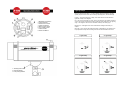
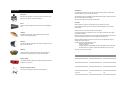
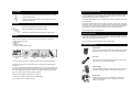
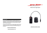
About Pro Line
Pro Line’s studio lighting equipment is recognised worldwide
as the leading brand of studio equipment for both the
professional and amateur photographer. The most innovative
technology, coupled with high quality manufacture and ease
of use puts Pro Line at the forefront for today’s studio or
location photographer.
OPERATING INSTRUCTIONS
PROLINE INTERNATIONAL
www.prolinestudio.co.uk
Lighting Setups
Below is a diagram of the basic 1, 2, 3 and 4 lighting setups. Each light is used for a
specific purpose and are known as the Primary, Fill, Background, and Rim/Flair light.
Primary – This is the main light in a setup, and in cases where it is used with other
lights will normally be the brightest.
1. Modelling Light Switch
2. Power Indicator
3. Flash Power Control
4. Photo Cell Switch
5. Mains Power Switch
6. Sync Cable Socket
7. Power Socket
8. Flash Test Button
1. 360 Deg Photo Cell
2. Umbrella Holder
3. Lamp Tilting Bracket
Fill – This is the second light in a setup, where a second light is not available a reflector
can be used to bounce light from the Primary light back to the subject from an opposing
angle. The Fill light is used to remove shadows created by the Primary light.
Background – A third light can be used to illuminate the background behind your
subject.
Rim/ Flair – This is used to add another dimension of illumination to your subject it can
help separate the subject from the background and accentuate details such as hair.
1 Light Setup
2 Light Setup
3 Light Setup
4 Light Setup
Safety Notes
Accessories
Barn Doors
Barn doors are designed to control the direction and spread of the
light. They can also be used with coloured gels.
The Apollo lights must not be used in an environment where moisture or flammable
vapour is likely to come into contact with the unit.
Avoid touching either the modelling or flash bulbs with bare hands. This will shorten the
life of the bulb and cause it to blacken.
Do not operate if the cord or unit has been damaged.
Snoot
A snoot focuses the light precisely and can be used to highlight an
area.
Operation
Please check the contents to ensure all the items are present and correct.
Fit the modelling bulb to the unit, and use the mains lead supplied to connect to the
mains supply.
Switch the unit on via the power switch on the back panel.
Umbrella
Umbrellas can be used to reflect or diffuse light and to create
cooling or warming lighting effects.
Reflector
The reflector attaches to the front of the light and helps to focus the
light in a specific direction.
Reflector
It is recommended that you charge the unit for 1 hour prior to initial use and/or after a
long period of inactivity.
Set the power control to desired level. The charge indicator will illuminate and the there
will be an audible beep when the unit is fully charged and ready to use.
Both the modelling bulb and the photo cell can be turned of independently using the
switches at the rear of the unit.
The flash unit can be triggered in three ways:
Manually using the test button.
Via the sync socket
Using the built in photocell enabling the unit to be triggered by any other flash,
the built in flash on a camera, a camera mounted flash gun or by infra-red.
We hope you enjoy using this lamp.
Used to reflect the light towards the subject and, depending on
what side is used, can produce a cooling or warming effect.
SPECIFICATIONS
Equipment Bag
The padded equipment bags help to protect the equipment either in
the studio or on the move.
Background Support System
Can be used to hang paper, cloth and vinyl backgrounds.
X-180 Apollo
X-300 Apollo
Output
180 w/s
300 w/s
Guide Number
35GN
48GN
Recharge Time
3.0 sec
3.6 sec
Colour Temp
5500 K
5500 K
Power Control
Full to 1/8 fully variable
Full to 1/8 fully variable
Modelling Lamp
50W
50W
Flash Duration
1/1000 sec
1/1000 sec
Triggering Methods
Slave / Infrared / Sync Cable
Slave / Infrared / Sync Cable
Sync Voltage
6V DC
6V DC
Light Stand
Replacing the Flash Tube
Set up the light stand to the required height and remove the white
plastic cap from the top.
The legs should be positioned as far apart as possible in order to
obtain the most stability.
Umbrella
Turn off the unit and disconnect from the mains supply and press the Flash Test Button
in order to discharge any stored power. It is recommended that you wait 30 minutes
before touching either the flash or modelling bulb.
Unwind the twisted trigger wire from the flash tube and gently pull the flash tube assembly out of the unit.
Remove the umbrella from the protective sleeve.
Pick up the replacement flash tube with either a clean cloth or paper towel, taking care
not to touch it with your bare hands, and gently but firmly insert it into the unit. Wind the
trigger wire back around the flash tube ensuring that it is not touching the metal reflector, (if the wire is in contact with any other part of the unit it will fail to operate).
Open the umbrella fully so that it locks into place.
Always replace with the correct flash tube.
Insert into the Umbrella Holder located directly under the light.
Softbox
Please check the contents to ensure all the items are present and correct (Fig 1):
Replacing the Fuse
The fuse is located directly above the Power Socket on the rear of the light. In order to
replace the fuse, unplug the power lead from both the mains and the light, the fuse tray
can then be pulled out and the fuse replaced.
The F-180 Apollo & F-300 Apollo lights require a 10 amp fuse.
1 x Black / Silver Outer Cover
1 x Speedring
4 x Rods
1 x Internal Diffuser
1 x Translucent Outer Diffuser Cover
Triggering Methods
Camera Flash
The Pro Line flash lights have built in Slave Sensors and so can be
triggered by the use of flash gun or by the cameras built in flash.
Fig 1
Fig 2
Fig 3
Fig 4
Fig 5
1. Place the black outer cover on a flat surface with the silver lining facing upwards.
2. Place the speedring in the centre of the outer cover with the widest part facing upwards (Fig 2).
3. Insert the rods into the speedring and locate the other end of one of the rods into one
of the small pockets located around the edge of the outer cover. Repeat this with all the
other rods, starting with the opposite rod to the one just fitted until all rods are in place
(Fig 3). The rods will bend sufficiently for this to happen.
4. Attach the inner diffuser onto the outer cover (Fig 4).
5. Attach the outer diffuser to the front of the softbox (Fig 5).
6. The softbox can now be fitted to the light.
Sync Lead
One end of the sync lead plugs into the camera and the other end
plugs into the sync socket of the flash light.
Infrared Trigger
The infrared trigger fits directly onto the hotshoe of the camera. The
test button should be pressed in order to start the charge cycle.
Radio Trigger
The radio trigger has two parts; a transmitter, that fits onto the
hotshoe of the camera and a receiver that plugs into the sync
socket of the flash light.