1
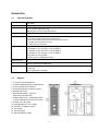
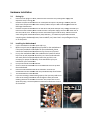
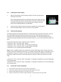
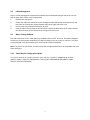
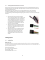
TWELVE HUNDRED V3
USER’S MANUAL
Congratulations on your purchase of the Antec Twelve Hundred V3.
Antec’s Twelve Hundred V3 gaming case combines maximum performance, cooling and compatibility in
a full-tower package. Thirteen drive bays, space for graphics cards as large as 17.5,” a CPU cutout, an
internal 2.5” SSD drive mount and newly integrated USB 3.0 round off a robust foundation for your
components. The Twelve Hundred V3 features a top Big Boy 200™ blue LED cooling fan, two rear blue
LED 120 mm fans and three front blue LED 120 mm fans. Apart from standard size power supplies, the
Twelve Hundred V3 can accommodate Antec’s CPX form factor PSUs.
The Twelve Hundred V3 comes without a power supply. Make sure you choose a power supply that is
compatible with your computer components and has a long enough power harness to reach your
motherboard and peripheral devices. We recommend our High Current Gamer, High Current Pro or CP
power supplies for the latest ATX specification compliance, broad compatibility, and power savings
capability.
At Antec, we continually refine and improve our products to ensure the highest quality. It’s possible that
your new case will differ slightly from the descriptions in this manual. This isn’t a problem; it’s simply an
improvement. As of the date of publication, all features, descriptions, and illustrations in this manual are
correct.
Disclaimer: This manual is not designed to cover CPU, RAM, or expansion card installation. Please
consult the motherboard manual for specific mounting instructions and troubleshooting. Before
proceeding, check the manual for your CPU cooler to find out if there are steps you must do before
installing the motherboard.
1
Table of Contents
Introduction
1.1
1.2
Case Specifications ....................................................................................3
Diagram......................................................................................................3
Hardware Installation Guide
2.1
2.2
2.3
2.4
2.5
2.6
2.7
2.8
2.9
2.10
Setting Up ..................................................................................................4
Motherboard Installation .............................................................................4
Power Supply Installation ...........................................................................5
Flexi-Drive Bay System ..............................................................................5
Internal 3.5” Device Installation ..................................................................5
External 5.25” Device Installation ...............................................................6
Internal 2.5” Device Installation ..................................................................6
Cable Management Compartment ..............................................................7
Water Cooling Platform ..............................................................................7
Three-Way SLI Configuration Option ..........................................................7
Connecting the Front I/O Ports
3.1
3.2
3.3
3.4
3.5
USB 2.0 Ports.............................................................................................8
USB 3.0 Port ..............................................................................................8
AC’97 / HD Audio Ports ..............................................................................9
Power Switch / Reset Switch / Hard Disk Drive LED Connectors................9
Rewiring Motherboard Header Connections ...............................................10
Cooling System
4.1
4.2
Included Fans .............................................................................................10
Washable Air Filters ...................................................................................12
2
Introduction
1.1
Case Specifications
Case Type
Full Tower
Color
Black
Dimensions
22.9” (H) x 8.4” (W) x 20.2” (D)
582 mm (H) x 213 mm (W) x 513 mm (D)
Weight
31.3 lbs / 14.2 kg
Cooling
- 2 rear 120 mm blue LED exhaust fan
- 1 top 200 mm Big Boy 200™ blue LED exhaust fan
- 3 front 120 mm blue LED intake fans with front speed control
- 1 window side panel 120 mm fan slot
- 1 middle 120 mm fan bracket
Drive Bays
13 Drive Bays:
- External 3 x 5.25"; Internal 9 x 3.5" for HDD, or
- External 6 x 5.25"; Internal 6 x 3.5" for HDD, or
- External 9 x 5.25"; Internal 3 x 3.5" for HDD or
- External 12 x 5.25 for HDD
- Internal 1 x 2.5" SSD bottom mount
Expansion Slots
7
Motherboard Size
Mini-ITX, microATX, Standard ATX
2 x USB 2.0
1 x USB 3.0
AC’97 / HD Audio In and Out
Front I/O Panel
1.2
Diagram
1. 2 x 120 mm rear blue LED fans
2. 1 x 200 mm Big Boy 200™ top blue LED fan
3. 3 x front 120 mm blue LED fans
4. 1 x window side panel 120 mm fan slot
5. Washable Air Filters
6. Motherboard Mount - Mini ITX,
MicroATX or Standard ATX
7. Power supply mount - Standard size PSUs
or Antec’s exclusive CPX form factor PSUs
8. 12 total 5.25” drive bays
9. 3 reconfigurable 3.5” drive cages
10. Internal 2.5” SSD drive mount
11. CPU cutout
12. Front I/O Panel
13. 200 mm Radiator mount
3
Hardware Installation
2.1
Setting Up
1.
3.
Place the case upright on a flat, stable surface so that the rear panel (power supply and
expansion slots) is facing you.
Remove the panel thumbscrews from a side panel and o
open
pen it by sliding it towards yourself.
Note: Place the panel thumbscrews carefully aside as they are NOT interchangeable with the
HDD cage thumbscrews.
Remove the panel thumbscrews from the other side panel and open it by sliding it towards you.
Place the screws carefully aside. Inside the case is the power supply mount at the lower rear of
the case and the 5.25” drive bay area with three HDD cages inside the bays. You will also find
some wiring with marked connectors (USB, PWR etc.), an installed I/O panel and a toolbox
containing more hardware (screws, brass standoffs, etc.) Note: Don’t use your fingernail to pry
or lift the panels.
2.2
Installing the Motherboard
1.
2.
Lay the case down so that the open side is up.
Make sure you have the appropriate I/O panel for the motherboard.
If the panel provided is not suitable for the motherboard, please
contact the motherboard manufacturer for the correct I/O panel.
Line up the motherboard with the standoff holes. Determine which
holes line up and remember where they are. Not all motherboards
will match with all of the provided screw holes, and this is not
necessary for proper functionality. Some standoffs may be pre
preinstalled for your convenience.
Lift up and remove the motherboard.
Screw in the brass standoffs to the threaded holes that line up with
the motherboard.
Place the motherboard on the brass standoffs. Screw in the
motherboard to the standoffs with the provided Phillips
Phillips-head screws.
The motherboard is now installed.
If you are installing a water cooling system, then you may need to run
some of the tubing outside the case through the hose ports with
rubber grommets on the back of the case. Also, make sure to read
about the pump / reservoir platform feature descr
described near the end
of the manual.
2.
3.
4.
5.
6.
7.
8.
4
2.3
Installing the Power Supply
1.
With the case upright, place the power supply on the four silicone pads on
the bottom of the case.
Note: Power supplies with fans on the bottom of the power supply will need
to be mounted so that the fan is facing the top of the case. Twelve Hundred
V3 provides mounting holes for power supplies with standard mounting
layouts to be installed upside up or upside down.
2.
3.
Push the power supply to the back of the case and align the mounting holes.
Attach the power supply to the case with the screws provided.
2.4
Flexi Drive Bay System
The Twelve Hundred V3 comes with twelve 5.25” external drive bays at the front of the case. There are
three HDD cages preinstalled inside the bottom nine 5.25” bays. Each HDD cage occupies three
consecutive 5.25” drive bays and can house three hard disk drives. For maximum flexibility you can
mount the HDD cage anywhere within the external drive bays (i.e., you are not limited to the bottom six
bays).
Possible Drive Bay combinations include but are not limited to:
• External 3 x 5.25” + internal 9 x HDD – default
• External 6 x 5.25” + internal 6 x HDD – by removing one HDD cage
• External 9 x 5.25” + internal 3 x HDD – by removing two HDD cages
• External 12 x 5.25” by removing all three HDD cages
Note: There is a middle fan bracket pre-installed on one of the HDD cages. Install a 120 mm fan to the
bracket so the air will be blown into the case, if you decide to use the HDD cage as a cooling duct to cool
your graphics card or CPU. However, this will stop you from installing your hard drives into this cage.
Remove the middle fan bracket from the HDD cage if you decide to mount your hard drives into this
cage.
• External 3 x 5.25” + internal 6 x HDD + cooling duct – by adding the middle fan to one of the HDD cages
(see Cooling System)
• External 6 x 5.25” + internal 3 x HDD + cooling duct – by adding the middle fan to one of the HDD cages
(see Cooling System)
2.5
1.
2.
3.
4.
Internal 3.5” Device Installation
Remove both side panels per the instructions in Setting Up.
Remove the cage thumbscrews fastening the HDD cage to the frame.
Slide the HDD cage forward out of the front of the case.
Mount the hard drive in the drive cage and fasten it using the long screws provided.
5
5.
6.
7.
Slide the HDD cage back into the case and fasten it with thumbscrews.
Connect the appropriate connector(s) from the power supply
to the device(s).
ce(s). Leave some slack in the connections so that
you can easily access the fan filters for cleaning.
There is a 120 mm fan pre-installed
installed into each cage. Connect
the 4-pin
pin connector to the power supply.
Note:: There is a middle fan bracket pre
pre-installed on one of
the HDD cages. Remove it from the cage if you decide to
mount your hard drives into this cage.
2.6
External 5.25” Device Installation
Note:: The HDD cages each occupy three consecutive drive bays, and will block
installation of larger devices such as optical drives, so please plan ahead before
installing your drives.
1. Remove both side panels per the instructions in Setting Up.
2. Remove the screws fastening the appropriate metal drive bay cover(s) to
the sides of the case.
3. Remove the cover(s).
4. If necessary, please remove the HDD cage that is
pre-installed in the bay.
5. Slide the 5.25” device into the bay from the front of the case.
6. Fasten the drive using the screws that came with your
drive.
7. Connect the appropriate power and interface connectors
from the power supply and motherboard to the device.
Make sure that you leave some slack in the connections
so that you can easily access the fan filters for cleaning.
8. Mount the other devices accordingly.
2.7
Internal 2.5” Device Installation
At the bottom of your case, there are mounting holes designed to support one
2.5” SSD device.
1. Locate the plastic bag labeled “For 2.5 HDD” and remove the 4 silicone
grommets.
2. Install the grommets into the four holes at the base of the case at the
bottom of the drive bay area as shown. You should install them with
the thick part of the grommets facing the inside of the case.
3. Lay the Twelve Hundred V3 on its side, and hold the drive in place on
top of the grommets.
4. Secure the device to the case with the screws provided, tightening the
screws with your fingers first, and then the screwdriver.
5. Connect the appropriate power and data cables to your device
6
2.8
Cable Management
There is a cable management compartment between the motherboard and right side panel. You can
tuck or route excess cables in this compartment.
1.
Remove both side panels
2.
Choose the cables you would like to pass through the holes behind the motherboard tray and
pull them out of the power supply chamber towards the right side of the case.
3.
Use the cable ties provided to hold them in place.
4.
Feed the cables back through the insertion point nearest the destination of the cable. Connect
the cable and then pull the slack back to the right side of the case.
2.9
Water Cooling Platform
This case comes with a 5.25” metal plate pre-installed in the 3rd 5.25” drive bay. This plate is designed
to allow you to easily mount components of a water cooling kit such as a pump or reservoir. The plate
can be mounted in any of the twelve 5.25” drive bays for maximum flexibility.
Note: The plate is not pre-drilled. You will need to drill the appropriate holes to be compatible with your
water cooling kit.
2.10
Three-Way SLI Configuration Option
The Twelve Hundred V3 has eight expansion slots, making it capable of supporting up to three
graphics cards in triple-SLI configuration. Consult your motherboard and graphics cards
manuals for more information.
7
Connecting the Front I/O Ports
Front I/O Ports and LEDs
Note: Please refer to your motherboard manual for specific pin outs or location of front panel
connectors.
1.
Connect the Reset switch (labeled RESET SW) to the motherboard at the RST connector. Polarity
(positive and negative) does not matter for switches.
2.
Power Switch (labeled POWER SW) connects to the PWR connector on the motherboard.
3.
There is no Power LED in this case. Three illuminated case fans will turn on when there is power
to the computer.
4.
Hard Drive LED (labeled H.D.D. LED) connects to the IDE connector. For LEDs, colored wires are
positive (+). White or black wires are negative (–). If the LED does not light up when the system
is powered on, try reversing the connection. For more info on connecting LEDs to your
motherboard, see your motherboard manual.
3.1
USB 2.0
Connect the front I/O panel USB cable to the USB header pin on your motherboard. Check the
motherboard manual to ensure that it matches the table below:
1
2
9 10
3.2
Pin
Signal Names
Pin
Signal Names
1
USB Power 1
2
USB Power 2
3
Negative Signal 1
4
Negative Signal 2
5
Positive Signal 1
6
Positive Signal 2
7
Ground 1
8
Ground 2
9
Key (No Connection)
10
Empty Pin
USB 3.0
There is a pre-routed cable for the front-panel USB 3.0 port. Plug the back end of this cable into an onboard USB 3.0 port on your motherboard to enable the front USB 3.0 port.
8
3.3
AC’97/HD Audio Ports
There is an Intel® standard 10-pin AC’97 connector and an Intel® 10-pin HDA (High Definition Audio)
connector linked to the front panel of the case.
Pin
1
Signal Names
(HDA)
Pin
Signal Names
(AC’97)
MIC2 L
1
MIC In
2
AGND
2
GND
3
MIC2 R
3
MIC Power
4
AVCC
4
NC
5
FRO-R
5
Line Out (R)
6
MIC2_JD
6
Line Out (R)
7
F_IO_SEN
7
NC
8
Key (no pin)
8
Key (no pin)
9
FRO-L
9
Line Out (L)
10
LINE2_JD
10
Line Out (L)
You can connect either the AC’97 or the HDA connector, depending on the model of the motherboard.
Locate the internal audio connectors from your motherboard or sound card and connect the
corresponding audio cable. Consult your motherboard or sound card manual for the pin-out positions.
Even if your system supports both audio standards, you may only use one connector.
3.4
Power Switch / Reset Switch / Hard Disk Drive LED Connectors
Connected to your front panel are LED and switch leads for power, reset, and HDD LED activity. Attach
these to the corresponding connectors on your motherboard. Consult your motherboard manual for
specific pin header locations. For LEDs, colored wires are positive ( + ). White or black wires are negative
( – ). If the LED does not light up when the system is powered on, try reversing the connection. For more
information on connecting LEDs to your motherboard, see your motherboard manual.
Note: Polarity (positive and negative) does not matter for switches. There is also no Power LED in this
case. The illuminated case fans will turn on when there is power to the computer.
9
3.5
Rewiring Motherboard Header Connections
There may come a time that you need to reconfigure the pin-out of a motherboard header connector.
Examples could be for your USB header, audio input header, or some other front panel connector such
as the Power Button connector.
Before performing any work, please refer to your motherboard manual or your motherboard
manufacturer's website to be sure of the pin-out needed for your connector. And we strongly
recommend making a notated drawing before beginning work so that you can recover if your work gets
disturbed.
1. Determine which wires you need to remove in
order to rewire your plug to match the USB pin-outs
on your motherboard (refer to your motherboard
manual). Working on one connector at a time, use
a very small flathead screwdriver or similar tool to
lift up on the black tab located beside the gold
posts (squares). This will allow you to easily slide
out the pins from the USB plug.
2. Working carefully so as not to damage the wires,
connectors, or pins, slowly remove the pin from
the connector. Repeat these steps for each wire
you need to change.
3. Working carefully so as not to damage the wires,
connectors or pins, slowly reinsert the pin into
the correct slot of the connector, then snap
closed the black tab that was lifted in step 1.
Repeat these steps for each wire you need to
change.
Cooling System
4.1
Included Fans
Big Boy 200™ fan:
The Twelve Hundred V3 comes with a Big Boy 200 mm blue LED fan. This fan has a three-speed switch
that lets you choose the speed best suited to your needs and a switch to turn on or off the blue LED. The
default fan speed setting is Low.
200 mm Fan Specifications:
Size: 200 x 30 mm three-speed fan
Rated Voltage: 12V DC
Operating Voltage: 10.8V ~ 13.2 V
10
Front TriCool™ LED Intake Fans:
The Twelve Hundred V3 comes with three 120 x 25 mm TriCool™ blue LED fans which are pre-installed in
front of each HDD cage to cool the hard drives. These fans are installed so the air will be blown into the
case. Each fan comes with a speed control knob at the front of the faceplate. Turn the knob clockwise
to increase the speed. The lowest speed is 1200 rpm while the highest speed is 2000 rpm. See the
following chart to get appropriate specification.
Rear TriCool™ LED Exhaust Fan
There are two 120 x 25 mm TriCool™ blue LED fans preinstalled at the rear of the case. The fans are
installed so the air will be blown out of the case. Each fan has a three-speed switch that lets you choose
between quiet, performance, or maximum cooling. These switches are located at the rear of the case.
The default fan speed setting is Low.
120 mm Fan Specifications:
Size: 120 x 25 mm TriCool™ Fan
Rated Voltage: 12V DC
Operating Voltage: 10.2V ~ 13.8V
Note: The minimum voltage to start a 120 mm TriCool™ fan is 5V. We recommend that you set the fan
speed switch to High if you choose to connect the fan(s) to a fan control device or to the Fan-Only
connector found on some Antec power supplies. A fan control device regulates the fan speed by varying
the voltage, which may start as low as 4.5V to 5V. Connecting a TriCool™ fan set on Medium or Low to a
fan-control device may result in the fan not being able to start because the already lowered voltage
from the fan control device will be further reduced by the TriCool™ circuitry below 5V.
Side Panel 120 mm Fan Slot
The side fan opening is there to enhance graphics card cooling. Just snap a fan into the bracket on the
side panel so that it blows air into the case.
Middle 120 mm Fan Bracket
The middle fan is designed to cool the CPU, graphics card or the power supply, depending on which
drive bays you install the HDD cage into. You can use the middle fan on any drive cage you do NOT
install hard drives in. This design is especially useful in cooling dual graphics card implementations.
1. To remove the black middle fan mount, press in on the clips that secure the bay to its cage.
2. Place a 120 mm fan inside the mount and press it into place so that the holes in the fan are secured to
the mount.
3. Use the long screws provided to secure the fan to the mount. Do not overtighten.
4. Run the power (and control switch if using a TriCool™ fan) through the cable guide that runs along the
side of the fan mount.
5. Clip the assembly onto the back of an empty HDD cage.
6. Connect the fan to the power supply.
11
4.2
Washable Air Filters
Front Air Filters – There is a filter located behind the faceplate of each HDD cage faceplates. There is a
total of three front air filters that come with the case by default.
To clean the filter:
1. Remove the cage thumbscrews fastening the HDD cage to the 5.25” drive bays and set them aside.
2. Slide the HDD cage forward about 1 or 2 inches. You will see the air filter behind the faceplate.
Note: There should be no need to disconnect the power or data connections from the HDD or the fan in
order to remove the filters for cleaning. Just make sure that you have left about 2 inches of slack in the
cables.
3. Lift the tab upwards to remove the filter.
Side Air Filter – There is a filter located in the side fan bracket. It is located on the inside of the side
panel, so you must open the side panel to access it. Remove the filter by sliding it out of the bracket.
From time to time it will be necessary to wash the installed air filters. Not washing the air filter will
result in high system temperatures and possible stability problems. We recommend checking the air
filter at least once a month initially. The frequency will change depending on environmental conditions
and system usage. Users who run their systems 24/7 will have to check their filters more often than
those who don’t use it every day.
12
Antec, Inc.
47900 Fremont Blvd.
Fremont, CA 94538
USA
tel: 510-770-1200
fax: 510-770-1288
Antec Europe B.V.
Stuttgartstraat 12
3047 AS Rotterdam
The Netherlands
tel: +31 (0) 10 462-2060
fax: +31 (0) 10 437-1752
Customer Support: US & Canada
1-800-22ANTEC
[email protected]
Europe
[email protected]
www.antec.com
© Copyright 2011 Antec, Inc.
All rights reserved.
All trademarks are the property of their respective
owners. Reproduction in whole or in part without
written permission is prohibited.
13