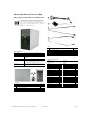
1
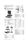
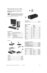
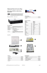
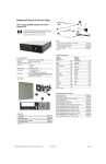
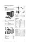
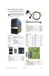
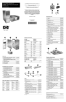
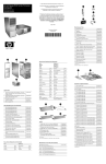
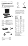
Illustrated Parts & Service Map
HP Compaq dc5800 Microtower Business PC
© 2008 Hewlett-Packard Development Company, L.P. The information contained herein is subject to change without notice. HP shall not be liable for
technical or editorial errors or omissions contained herein. Intel, Celeron,
Core 2 Duo, Core Quad, and the Intel logo are trademarks or registered trademarks of the Intel Corporation and its subsidiaries in the U. S. and other countries.
Document Number 481403-001.
1st Edition February 2008.
Cables
Key Specifications
1
Front I/O with USB
2
Power switch cable assembly
460885-001
460886-001
3
SATA HDD cable, 18 inch, 1 straight end, 1 angled end
393958-001
391739-001
4
SATA cable, 19 inch, 2 straight ends
Processor Type
Intel Core 2 Duo, Intel Core 2 Quad, Pentium, Celeron
*
SATA cable, 17 inch, 2 straight ends
453317-001
RAM Type
DDR2-SDRAM DIMMs, PC2-6400 (800 MHz) non-ECC
*
DMS-59 to dual VGA cable
463023-001
Maximum RAM Supported
8 GB
*Not shown
Expansion Slots
•
•
•
Graphics Adapter
Intel GMA 3100 integrated
Keyboards (not illustrated)
Drive Support
•
•
•
•
PS/2, Basic
USB, Basic
USB SmartCard
I/O Interfaces
Serial (2, 1 optional), optional parallel, USB 2.0 (8), RJ-45,
audio in (2), audio out (2), PS/2 ports (2), VGA, DVI-D
1 PCIe-x16
2 PCIe-x1
1 PCI
(2) 5.25-inch external bays
(1) 3.5-inch external bay
(2) 3.5-inch internal hard drive bays (SATA 3.0 Gb/s)
(1) diskette drive or (1) media card reader
Spare Parts
System Unit
1
2
Access panel
Front bezel
461859-001
460883-001
3
Power supply, 300W
460879-001
3
Power supply, 300W, 80% efficient
460880-001
*
5.25-inch bezel blank
335937-001
*
Chassis
not spared
435302-xxx
435382-xxx
435385-xxx
Arabic
-171
Kazakh
-DF1
Belgian
-181
Korean (Hangul)
-AD1*
BHCSY
-B41
LA Spanish
-161
Brazilian Portuguese
-201
Norwegian
-091
Czech
-221
Polish
-241
Danish
-081
Portuguese
-131
Dutch
-331
Romanian
-271
Estonian
-CA1
Russian
-251
Finnish
-351
S. Chinese
-AA1
French
-051
Slovakian
-231
French Arabic
-DE1
Spanish
-071
French Canadian
-121
Swedish
-101
German
-041
Swiss
-111
Greek
-151
Taiwanese
-AB1
Hebrew
-BB1
Thai
-281
Hungarian
-211
Turkish “F”
-541
Icelandic
-DD1
Turkish “Q”
-141
International
-B31
U.S.
-001
Italian
-061
U.K.
-031
Japanese
-291
*For 435385, Korean = -KD1
* Not shown
dc5800 Illustrated Parts & Service Map, MT Chassis
481403-001
page 1
Standard and Optional Boards (not illustrated)
Memory modules:
512 MB, PC2-6400, CL6
418952-001
1 GB, PC2-6400, CL6
418951-001
2 GB, PC2-6400, CL6
457624-001
Other boards:
Belkin 802.11a/g WLAN adapter for use in the United States and most of the
world
Miscellaneous Parts
1
2
Second serial port, LP
392414-001
Chassis fan
460884-001
3
Fan duct
460882-001
4
Heatsink with alcohol pad and factory-applied thermal grease
460897-001
*
Fan duct
463721-001
*
System board tray
460881-001
*
Printer port, LP
465339-001
*
Mouse, PS2, optical
417966-001
*
Mouse, optical
390938-001
*
Mouse, USB laser
459821-001
*
Battery, real-time clock
153099-001
*
Internal speaker
392413-001
391866-002
Belkin 802.11a/g WLAN adapter for use in the rest of the world
391866-001
ATI HD X2400, PCIEx16, DMS-59 and TV outputs, 256MB graphics adapter
462477-001
nVidia Quadro NVS 290, 256MB, PCI-E graphics adapter
456137-001
Broadcom NetXtreme GbE PCI-E NIC, FH
430654-001
56K modem, Agere 2006 PCI Hi-Speed, FH
398661-001
nVidia GeForce 8400 GS 256-MB video card with DMS-59 and TV
(S-Video) outputs, FH
461450-001
nVidia GeForce 8400 GS 256-MB video card with DMS-59 and TV
(S-Video) outputs, LP
445743-001
Nvidia Quadro NVS290 256-MB PCIe graphics card
460815-001
DVI, SDVO graphics card, FH
398333-001
HP FireWire IEEE 1394 PCI card, 2 external, 1 internal port, FH
441448-001
Intel Pro 1000 PT Gigabit PCIe NIC, FH
398754-001
ReadyBoost module, 1 GB
462851-001
System boards with thermal grease, alcohol pad, and CPU socket cover:
System board
461536-001
System board, for Russia only
462850-001
Intel Celeron Processors with alcohol pad and thermal grease:
430, 512-KB cache, 1.80 GHz
449165-001
420, 512-KB cache, 1.60 GHz
449164-001
Intel Celeron Dual-Core Processors with alcohol pad and thermal grease:
E1200, 512-KB cache, 1.60 GHz
468589-001
Intel Core 2 Quad Processors with alcohol pad and thermal grease:
*Not shown
LP = Low profile
Q6600, 8-MB cache, 2.40 GHz
452451-001
Intel Core 2 Duo Processors with alcohol pad and thermal grease:
System Board
E8400, 6-MB cache, 3.00 GHz
466169-001
E8200, 6-MB cache, 2.67 GHz
466171-001
E6750, 4-MB cache, 2.66 GHz
450791-001
E6550, 4-MB cache, 2.33 GHz
450694-001
E4600, 2-MB cache, 2.40 GHz
462569-001
E4500, 2-MB cache, 2.20 GHz
449452-001
Intel Pentium Dual-Core 2 Processors with alcohol pad and thermal grease:
E2200, 1-MB cache, 2.20-GHz
465216-01
E2180, 1-MB cache, 2.00-GHz
457656-01
Mass Storage Devices (not illustrated)
Diskette drive with bezel
431452-001
Media card reader, 3.5-inch
407187-001
16X SATA DVD±RW and CD-RW drive with LightScribe
447310-001
16X SATA DVD-ROM drive
419496-001
48X CD-RW/DVD-ROM combo drive
419497-001
500 GB SATA hard drive
457909-001
250 GB, 7200-RPM SATA hard drive, 8-MB cache
449980-001
250 GB, 7200-RPM SATA hard drive, 8-MB cache
440747-001
160 GB, 7200-RPM SATA hard drive, 8-MB cache
449979-001
160 GB, 7200-RPM SATA hard drive, 8-MB cache
440499-001
160 GB, 10000-RPM SATA hard drive, 16-MB cache
439995-001
System Board Connectors and Jumpers (position of some untitled
components may vary in location)
80 GB, 7200-RPM SATA hard drive, 8-MB cache
449978-001
80 GB, 7200-RPM SATA hard drive, 8-MB cache
440754-001
J9
RJ-45 over dual USB
P5
Power button/LED
80 GB, 10000-RPM SATA hard drive, 16-MB cache
439994-001
J10
Quad stack USB
P52
Second serial port
J20
PCI slot 1
P53
Serial port connector
J31
PCIe X1, slot 1
P6
Internal speaker
J32
PCIe X1, slot 2
P60
SATA0
J41
PCIe X16
P61
SATA1
J66
Keyboard
P62
SATA4
J67
Mouse
P63
SATA5
J69
VGA connector
P8
CPU fan
J78
Double stack audio connector
P9
System fan
P1
Main power
SW50
Clear CMOS
P10
Diskette drive
XBT1
Real-time-clock battery
P126
Parallel connector
XMM1
DIMM 1
P150
Media reader
XMM2
DIMM 2
P23
Front audio
XMM3
DIMM 3
P24
Front USB
XMM4
DIMM 4
P25
ReadyBoost
XU1
Processor
P3
CPU power
dc5800 Illustrated Parts & Service Map, MT Chassis
481403-001
page 2
Setup Utility
Diagnostic LEDs
Basic system information is maintained in the Setup Utility held in the system ROM, accessed
by pressing the F10 key when prompted (on screen) during the boot sequence.
Color
Beeps
LED Activity
State/Message
Computer Setup Menu
Green
none
On
Computer on
Heading
Option/Description
Green
none
1 blink every 2 seconds
Suspend to RAM Mode
File
System Information - Lists the following main system specifications:
Red
2
2 blinks every second followed
by a 2 second pause
•
•
•
•
•
•
•
Product name
SKU number (some models)
Processor type/speed/stepping
Cache Size (L1/L2)
Memory size/speed/channels
Integrated MAC Address
•
•
•
•
•
System BIOS
Chassis serial number
Asset tracking number
ME firmware version
ME management mode
•
•
Red
3
3 blinks, 1 blink every second
followed by a 2 second pause
Processor not installed (not indicator
of bad processor).
Red
4
4 blinks, 1 blink every second
followed by a 2 second pause
Power failure (power supply
overload).
Red
5
5 blinks, 1 blink every second
followed by a 2 second pause
Pre-video memory error.
Replicated Setup - Save to Removable Media and restore from Removable Media
Red
6
6 blinks, 1 blink every second
followed by a 2 second pause
Pre-video graphics error.
Default Setup: Save Current Settings as Default, Restore Factory Settings as
Default
Red
7
7 blinks, 1 blink every second
followed by a 2 second pause
System board failure (ROM detected
failure prior to video).
Red
8
8 blinks, 1 blink every second
followed by a 2 second pause
Invalid ROM based on bad checksum.
Save Changes and Exit - Saves changes to system configuration or default settings and exits Computer Setup.
Red
9
9 blinks, 1 blink every second
followed by a 2 second pause
System powers on but is unable to
boot.
Device Configuration - Lists all installed BIOS-controlled storage devices. The
following options are available:
• Diskette Type(Legacy Diskettes only)-3.5” 1.44 MB and 5.25” 1.2 MB
• Drive Emulation
• Emulation Type - ATAPI Zip drive, hard disk, legacy diskette, CD-ROM
drive, and ATAPI LS-120 drive
• Multisector Transfers (ATA disks only)
• Translation Mode (ATA disks only)
• Translation Parameters (ATA disks only)
• SATA Default Values
Red
10
10 blinks, 1 blink every second
followed by a 2 second pause
Bad option card.
none
none
System does not power on and
LEDs are not flashing
System unable to power on.
About - Displays copyright notice.
Set Time and Date - Allows you to set system time and date.
Flash System ROM - Allows you to select a drive containing a new BIOS.
Apply Defaults and Exit - Applies the selected default settings and clears any
established passwords.
Ignore Changes and Exit - Exits Setup without applying or saving any changes.
Storage
Storage Options
• Removable Media Boot
• Legacy Diskette Write
DPS Self-Test - Allows you to execute self-tests on ATA hard drives.
Boot Order - Allows you to specify boot order.
Shortcut to Temporarily Override Boot Order
Security
Setup Password - Allows you to set and enable the setup (Administrator) password.
Power-On Password - Allows you to set and enable power-on password.
Password Options - When any password exists allows you to lock legacy
resources, enable/disable network server mode, specify password requirement for
warm boot, and allows you to enable/disable Setup Browse Mode.
failure. For example, if a power failure were to occur during a BIOS upgrade, the ROM flash
would be incomplete. This would render the system BIOS unusable. The Boot Block is a flashprotected section of the ROM that contains code that checks for a valid system BIOS image
when the system is turned on.
• If the system BIOS image is valid, the system starts normally.
• If the system BIOS image is not valid, a failsafe Boot Block BIOS provides enough support
to search removable media for BIOS image files. If an appropriate BIOS image file is found,
it is automatically flashed into the ROM.
When an invalid system BIOS image is detected, the system power LED will blink red 8 times,
one blink every second. Simultaneously, the speaker will beep 8 times. If the portion of the
system ROM containing the video option ROM image is not corrupt, Boot Block Emergency
Recovery Mode will be displayed on the screen.
To recover the system after it enters Boot Block Emergency Recovery Mode, complete the
following steps:
1. Turn off the computer.
Device Security - Enables/disables all I/O ports, audio, network controllers,
SMBus controller, and embedded security devices.
2. Insert a flash drive or CD containing the BIOS image in the root directory. The media must be
formatted using the FAT12, FAT16, or FAT32 file system.
Network Service Boot - Enables/disables boot from OS on a server.
3. Turn on the computer. If no appropriate BIOS image is found, you will be prompted to insert
media containing a BIOS image file. The system will automatically flash the ROM. After a
successful flash, the system will either automatically restart or prompt the user to unplug the
unit, wait 5 seconds, reattach the power cord, and then press the power button.
DriveLock Security - Allows you to assign/modify a hard drive password for
added security.
4. Remove the removable media used to upgrade the BIOS.
5. Turn the power on to restart the computer.
System Security (some models) - Allows you to enable/disable:
• Data Execution Prevention
• Virtualization Technology
• Virtualization Technology Directed I/O
• Trusted Execution Technology
• Embedded Security Device Support
• OS management of Embedded Security Device through OS
• Virtual Appliance options
• Smart Card BIOS Password Support
NOTE: BitLocker prevents Windows Vista from booting when a CD containing the BIOS image
file is in an optical drive. If BitLocker is enabled, remove this CD before attempting to boot to
Windows Vista.
Password Security
Establishing a Setup password using computer setup
Setup Security Level - Provides method to allow users limited access to change
specified setup options without knowing Setup password.
Advanced
Boot Block Emergency Recovery Mode
Smart Cover (some models) - Allows you to lock/unlock cover lock and set status
of cover removal sensor.
System IDs - Allows you to set Asset tag, ownership tag, Chassis serial number,
UUID, and keyboard locale setting.
Power
Processor thermal protection
activated.
Fan blocked or not turning.
Heatsink not properly attached.
OS Power Management - Allows you to enable/disable Runtime Power Management, Idle Power Savings, ACPI S3 Hard Disk Reset, ACPI S3 PS2 Mouse
Wakeup, USB Wake on Device Insertion (some models), Unique Sleep State
Blink Rates.
1. Turn on or restart the computer. If you are in Windows, click Start > Shut Down > Restart.
2. As soon as the computer is turned on, press F10 when the monitor light turns green to enter
Computer Setup. Press Enter to bypass the title screen, if necessary. If you do not press F10
when prompted, a restart will be necessary.
3. Select Security > Setup Password and follow the instructions on the screen.
Hardware Power Management - Allows you to enable/disable SATA bus power
management.
4. Before exiting, click File > Save Changes and Exit.
Thermal - Allows you to control minimum permitted fan idle speed.
Changing a Power-on or Setup password
1. Turn on or restart the computer. If you are in Windows, click Start > Shut Down > Restart.
Power-On Options - Allows you to set:
• POST mode - QuickBoot, FullBoot, or FullBoot every 1-30 days.
• POST messages - Enable/disable
• MEBx Setup prompt - Enable/disable or hidden/displayed
• F9 prompt - Enable/disable
• F10 prompt - Enable/disable
• F11 prompt - Enable/disable
• F12 prompt - Enable/disable
• Factory Recovery Boot Support - Enable/disable
• Option ROM prompt - Enable/disable
• Remote wakeup boot source - Remote server/local hard drive
• After Power Loss - Off/on/previous state
• POST Delay - None, 5, 10, 15, or 20 seconds
• Limit CPUID Maximum Value to 3
2. If you want to change the Setup password, as soon as the computer is turned on, press F10
when the monitor light turns green to enter Computer Setup. Press Enter to bypass the title
screen, if necessary.
3. If you want to change the Power-On password, when the key icon appears, type your current
password, a slash (/) or alternate delimiter character, your new password, another slash (/) or
alternate delimiter character, and your new password again as shown:
current password/new password/new password.
NOTE: Type the new password carefully since the characters do not appear on the screen.
4. Press Enter.
The new password will take effect the next time the computer is restarted.
Execute Memory Test (some models) -Restarts computer and executes POST
memory test.
BIOS Power-On - Allows you to set the computer to turn on at a preset time.
Onboard Devices - Allows you to set resources or disable onbrd system devices.
Deleting a Power-on or Setup password
1. Turn on or restart the computer. If you are in Windows, click Start > Shut Down > Restart.
PCI Devices - Lists installed PCI devices with their IRQ settings and allows you
to reconfigure IRQ or disable devices.
2. To delete the Setup password, as soon as the computer is turned on, press F10 when the
monitor light turns green to enter Computer Setup. Press Enter to bypass the title screen, if
necessary.
PCI VGA Configuration - Allows you to specify which VGA controller will be
used when multiple video adapters are available.
3. To delete the Power-on password, when the key icon appears, type the current password
followed by a slash (/) or alternate delimiter character as shown: currentpassword/
Bus Options (some models) - Allows you to enable/disable PCI SERR# Generation and PCI VGA palette snooping.
4. Press Enter.
Device Options - Allows you to set:
• Printer Mode - Bi-Directional, EPP & ECP, Output Only
• Num Lock state at power-on - off/on
• S5 Wake on LAN - enable/disable
• Integrated Video - enable/disable
• Multi-Processor - enable/disable
• Internal speaker (some models) - enable/disable
• Monitor Tracking - enable/disable
• NIC PXE Option ROM Download - enable/disable
dc5800 Illustrated Parts & Service Map, MT Chassis
481403-001
page 3
HP Insight Diagnostics
The HP Insight Diagnostics utility allows you to view information about the hardware configuration of the computer and perform hardware diagnostic tests on the subsystems of the computer. The utility simplifies the process of effectively identifying, diagnosing, and isolating
hardware issues.
The Survey tab is displayed when you invoke HP Insight Diagnostics. This tab shows the current configuration of the computer. From the Survey tab, there is access to several categories of
information about the computer. Other tabs provide additional information, including diagnostic
test options and test results. The information in each screen of the utility can be saved as an html
file and stored on a diskette or USB HP flash drive.
Use HP Insight Diagnostics to determine if all the devices installed on the computer are recognized by the system and functioning properly. Running tests is optional but recommended after
installing or connecting a new device.
You should run tests, save the test results, and print them so that you have printed reports available before placing a call to the Customer Support Center.
Insight Diagnostics may be found on the Documentation and Diagnostics CD that shipped with
the computer. The tool may also be downloaded from the HP Web site using the following procedure:
1. Go to www.hp.com
219-ECC Memory
Module Detected ECC
Modules not supported
on this Platform
Recently added memory
module(s) support
ECC memory error correction.
If additional memory was recently
added, remove it to see if the problem remains.
301-, 304-Keyboard
error
Keyboard failure.
Check keyboard connection or keys.
Check connector for bent of missing
pins. Replace keyboard. If 304, possible system board problem.
501-Display Adapter
Failure
Graphics display controller.
3. Check monitor connection.
4. Replace graphics card.
510-Flash Screen
Image Corrupted
Flash Screen image has
errors.
Reflash the system ROM with the
latest BIOS image.
511-CPU, CPUA, or
CPUB Fan not
Detected
CPU fan is not connected or
may have malfunctioned.
1. Reseat CPU fan.
3. Enter the product number (for example, dc5800) in the text box and press the Enter key.
4. Select the specific product.
512-Chassis, Rear
Chassis, rear chassis, or
Chassis, or Front Chas- front chassis fan is not consis Fan not Detected
nected or may have malfunctioned.
6. Click the Diagnostics link.
7. Select HP Insight Diagnostics Offline Edition.
8. Select the proper language and click Download.
CPU or chassis fan is not
connected or may have malfunctioned.
1. Turn off the computer and any external devices, and disconnect the power cord from the
power outlet.
2. Remove the access panel.
3. On the system board, press and hold the CMOS button for 5 seconds.
4. Replace the access panel, external devices, and reconnect the power cord.
5. Turn on the computer.
You will receive POST error messages after clearing CMOS and rebooting advising you that
configuration changes have occurred. Use Computer Setup to reset any special system setups
along with the date and time.
Common POST Error Messages
2. Expansion board option
ROM checksum.
912-Computer Cover
Has Been Removed
Since Last System
Startup
Computer cover was
removed since last system
startup.
No action required.
1151-Serial Port A
Address Conflict
Detected
1152-Serial Port B
Address Conflict
Detected
1155-Serial Port
Address Conflict
Detected
• Both external and internal
serial ports are assigned to
COM1.
• Both external and internal
serial ports are assigned to
COM2.
• Both external and internal
serial ports are assigned to
same IRQ.
1. Remove any serial port expansion
cards.
1720-SMART Hard
Drive Detects Imminent Failure
Hard drive is about to fail.
(Some hard drives have a
hard drive firmware patch
that will fix an erroneous
error message.)
1. Determine if hard drive is giving
correct error message. Enter
Computer Setup and run the Drive
Protection System test under
Storage > DPS Self-test.
Recommended Action
1. Verify ROM, reflash if required
3. Back up contents and replace hard
drive.
1796-SATA Cabling
Error
One or more SATA devices
are improperly attached. For
optimal performance, the
SATA 0 and SATA 1 connectors must be used before
SATA 4 and SATA 5.
Ensure SATA connectors are used in
ascending order. For one device, use
SATA 0. For two devices, use SATA
0 and SATA 1. For three devices, use
SATA 0, SATA1, and SATA 4.
1797-SATA Drivelock
is not supported in
RAID mode.
Drivelock is enabled on one
or more SATA hard drives,
and they cannot be accessed
while the system is configured for RAID mode.
Either remove the Drivelocked
SATA device or disable the Drivelock feature. To disable the Drivelock feature, enter Computer Setup,
change Storage > Storage Options
> SATA Emulation to IDE, and
select File > Save Changes and
Exit. Re-enter Computer Setup and
select Security > Drivelock. For
each listed Drivelock-capable SATA
device, ensure Drivelock is Disabled.
Lastly, change Storage > Storage
Options > SATA Emulation back to
RAID and select File > Save
Changes and Exit.
1801-Microcode Patch
Error
Processor not supported by
ROM BIOS.
1. Upgrade BIOS to proper version.
2200-PMM Allocation
Error during MEBx
Download
Memory error during POST
execution of the Management Engine (ME) BIOS
Extensions option ROM
1. Reboot the computer.
6. Replace system board.
DMA, timers
162-System Options
Not Set
Configuration incorrect.
RTC battery may need to be
replaced.
1. Clear CMOS.
Run Computer Setup and check configuration in Advanced > Onboard
Devices.
Reset date and time in Control Panel.
If problem persists, replace RTC battery.
163-Time & Date Not
Set
Invalid time or date in configuration memory.
RTC (real-time clock) battery may need to be
replaced.
Reset the date and time under Control
Panel (Computer Setup can also be
used). If the problem persists,
replace the RTC
battery.
2. Remove expansion boards.
3. Replace system board.
163-Time & Date Not
Set
CMOS jumper may not be
properly installed.
Check for proper placement of the
CMOS
jumper if applicable.
164-Memory Size
Error
Memory amount has
changed since the last
boot (memory added or
removed).
Press the F1 key to save the memory
changes.
-or1. Run Setup (F10).
Incorrect memory configuration.
2. Make sure the memory module(s)
are installed properly.
3. If third-party memory has been
added, test using HP-only
memory.
4. Verify proper memory module
type.
1. Run Setup (F10).
2. Change the processor.
2. Unplug the power cord, re-seat the
memory modules, and reboot the
computer.
3. If the memory configuration was
recently changed, unplug the
computer, restore the original
memory configuration, and reboot
the computer.
4. If the error persists, replace the
system board.
Invalid Electronic
Serial Number
Electronic serial number is
missing.
Enter the correct serial number in
Computer Setup.
Network Server Mode
Active and No Keyboard Attached
Keyboard failure while Network Server Mode enabled.
1. Reconnect keyboard with
computer turned off.
2. Ensure memory modules are
correctly installed.
2. Check connector for bent or
missing pins.
3. Verify proper memory module
type.
3. Ensure that none of the keys are
depressed.
4. Remove and replace the identified
faulty memory module(s).
5. If the error persists after replacing
memory modules, replace the
system board.
214-DIMM Configuration Warning
3. Reconfigure card resources and/or
run Computer Setup or Windows
utilities.
3. If expansion board recently added,
remove to see if problem remains.
103-System Board
Failure
A memory module in memory socket identified in the
error message is missing
critical SPD information, or
is incompatible with the
chipset.
2. Clear CMOS.
2. Apply hard drive firmware patch
if applicable.
5. If message disappears, may be
problem with expansion card.
213-Incompatible
Memory Module in
Memory Socket(s) X,
X, ...
2. Reseat fan cable.
2. Remove suspected card, reboot
4. Clear CMOS.
RAM failure.
1. Reseat CPU of chassis fan.
3. Replace CPU or chassis fan.
Clearing CMOS
Description
2. Reseat fan cable.
514-CPU or Chassis
Fan not Detected
NOTE: The download includes instructions on how to create a bootable CD.
101-Option ROM Error 1. System ROM checksum.
1. Reseat chassis, rear chassis, or
front chassis fan.
3. Replace chassis, rear chassis, or
front chassis fan.
5. Select the OS.
201-Memory Error
2. Reseat fan cable.
3. Replace CPU fan.
2. Click the Software & Download driver link.
Screen Message
1. Reseat graphics card.
2. Clear CMOS.
1. Verify proper memory module
type.
4. Replace keyboard.
Parity Check 2
Parity RAM failure.
Third-party graphics card
may be causing a problem.
System will not boot
without fan
CPU fan not installed or dis- 1. Remove computer cover, press
connected.
power button, see if processor fan
spins. If processor fan not
spinning, make sure fan's cable is
plugged onto system board
header. Ensure heatsink is
properly seated and installed.
2. Try another memory socket.
3. Replace DIMM with a module
conforming to the SPD standard.
Populated DIMM configura- Rearrange the DIMMs so that each
tion is not optimized.
channel has the same amount of
memory.
dc5800 Illustrated Parts & Service Map, MT Chassis
481403-001
Run Computer Setup and Diagnostic
utilities. Remove third-party graphics card to see if problem goes away.
2. If fan is plugged in and heatsink is
properly seated but fan does not
spin, then replace heatsink
assembly.
page 4