1
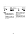
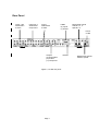
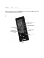
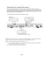
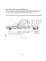
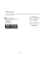
Model VS-560 User Manual 9 Input A/V Switcher with HDMI, Component Video, Digital Audio, Automatic Input Mode and Volume Equalization Online Product Registration http://www.simaproducts.com Package Contents: 1 - VS-560 A/V Switcher Unit 1 - Power Adapter, (120-220VAC input, 5V DC output) 1 – Universal Remote Control (PN – 52466) 1 - Instruction Manual for VS-560 (PN-21793) 1 – Instruction manual for remote control 2009 by Sima Products Corporation. All rights reserved. No part of this publication may be reproduced or transmitted in any form or by any means without prior written permission from Sima Products Corp. Page 2 Caution: IMPORTANT SAFEGUARDS FOR AUDIO PRODUCTS. PLEASE READ CAREFULLY THE FOLLOWING IMPORTANT SAFEGUARDS THAT ARE APPLICABLE TO YOUR EQUIPMENT 1. Read instructions - All the safety and operating instructions should be read before the appliance is operated. 2. Retain instructions - The safety and operating instructions should be retained for future reference. 3. Heed Warnings - All warnings on the appliance and in the operating instructions should be adhered to. 4. Follow instructions - Follow all operating and use instructions. 5. Water and Moisture - the appliance should not be used near water - for example: near a bathtub, washbowl, kitchen sink, laundry tub, in a wet basement or near a swimming pool. 6. Ventilation - The appliance should be located so that its location or position does not interfere with proper ventilation. For example: the appliance should not be situated on a bed, sofa, rug or similar surface that may block the ventilation openings. 7. Heat - the appliance should be situated away from heat sources such as radiators, registers, stoves or other heat-producing appliances. 8. Power sources - the appliance should be connected to a power supply only of the type described in the operating instructions or as marked on the appliance. 9. Grounding or polarization. - Precautions should be taken so that the polarization or grounding means of the appliance is not defeated. Caution: To prevent electric shock, match the wide blade of this plug to the wide slot, fully insert. Do not use this polarized plug with an extension cord, receptacle or other outlet unless the blades can be fully inserted to prevent blade exposure. 10. Power cord Protection - Power supply cords should be routed so they are not likely to be walked on or pinched by items placed upon or against them, paying particular attention to cords at plugs, convenience receptacles, and where they exit from the appliance. 11. Cleaning - Wipe unit with a damp cloth occasionally to keep it looking new. Do not use harsh chemicals, cleaning solvents or strong detergents. 12. Nonuse periods - The power cord of the appliance should be unplugged from the outlet when left unused for a long period of time. 13. Object and Liquid entry - Care should be taken so that objects do not fall and liquids are not spilled into the enclosure through openings. 14. Damage requiring service - The appliance should be serviced by qualified personnel when: the power cord has been damaged, objects have fallen or liquids spilled into the appliance, the appliance has been exposed to rain, does not appear to operate normally or exhibits a marked change in performance or the unit has been dropped or the enclosure damaged. 15. Service - The user should not attempt to service the appliance beyond that described in the operating manual. All other servicing should be referred to qualified service personnel. Notice to Users The system may cause interference to a TV or radio even when it is operating properly. To determine whether the system is causing the interference, turn it off. If the interference goes away, the system is causing the interference. NOTE: This equipment has been tested and found to comply with the limits for a class B digital device, pursuant to part 15 of the FCC Rules. These limits are designed to provide reasonable protection against harmful interference in a residential installation. This equipment generates, uses, and can radiate radio frequency energy and, if not installed and used in accordance with the instructions, may cause harmful interference to radio communications. However, there is no guarantee that interference will not occur in a particular installation. If this equipment does cause harmful interference to radio or television reception, which can be deter-mined by turning the equipment off and on, the user is encouraged to try to correct the interference by one or more of the following measures: • Reorient or relocate the receiving antenna. • Increase the separation between the equipment and receiver. • Connect the equipment into an outlet on a circuit different from that to which the receiver is needed. • Contact your dealer for help. This device complies with part 15 of the FCC Rules. Operation is subject to the following two Conditions: 1. This device may not cause harmful interference. 2. This device must accept any interference received, including interference that may cause undesired operation. Warning: Changes or modifications to this unit not expressly approved by the party responsible for compliance could void the user’s authority to operate the equipment Page 3 Table of Contents PACKAGE CONTENTS: ................................................................................................................................................ 2 CAUTION: ........................................................................................................................................................................ 3 INTRODUCTION ............................................................................................................................................................ 6 FRONT PANEL................................................................................................................................................................ 7 CONTROLS ............................................................................................ .......................................................................... 7 REAR PANEL................................................................................................................................................................... 8 IR UNIVERSAL REMOTE CONTROL........................................................................................................................ 9 TYPICAL HOOK UP..................................................................................................................................................... 10 BASIC HOOK-UP #1: CONNECTING TWO SOURCES ......................................................................................... 11 BASIC HOOK-UP #2: CONNECTING DIFFERENT VIDEO TYPES .................................................................... 12 BASIC HOOK-UP #3: CONNECTING HDMI SOURCES........................................................................................ 13 OPERATION .................................................................................................................................................................. 14 POWER.................................................................................................. ........................................................................ 14 AUTO INPUT MODE............................................................................... ........................................................................ 14 VOLUME EQUALIZATION ADJUSTMENT ................................................ ........................................................................ 14 DIGITAL AUDIO CONVERSION ............................................................... ........................................................................ 14 HOW IT WORKS........................................................................................................................................................... 15 SIMPLIFIED BLOCK DIAGRAM ............................................................... ........................................................................ 15 AUTOMATIC INPUT SENSING ................................................................. ........................................................................ 16 LCD SCREEN................................................................................................................................................................. 16 RS-232C INTERFACE................................................................................................................................................... 18 RS-232C CONNECTION......................................................................... ........................................................................ 18 RS232 COMMAND STRUCTURE ............................................................ ........................................................................ 19 TROUBLE SHOOTING ................................................................................................................................................ 20 TERMS ............................................................................................................................................................................ 20 TECHNICAL SPECIFICATIONS................................................................................................................................ 21 LIMITED WARRANTY................................................................................................................................................ 22 SYSTEM ORGANIZATION CHART.......................................................................................................................... 23 Page 4 Introduction Congratulations on purchasing Sima’s Model VS-560, 9 Input A/V Switcher with HDMI, Component Video, Digital Audio, Automatic Input Mode and Volume Equalization. It has been designed for use with Home Theater, DSS Satellite, DVD, HDTV, Video Games, Audio Recording Equipment, as well as for background music applications. The VS-560 has the following features: • High Bandwidth - low noise audio / video switching for today’s high quality systems. • Nine A/V Inputs plus HDMI, component video and digital audio - to allow you to add more A/V sources such as HDMI, DVD, satellite dish, VCR, HDTV, games, and more to your TV and home theater system. • Convenient Front Panel - A/V input for connecting camcorder or portable video player. • Front panel LCD screen – displays input selection, channel information, video format and volume level. • Video Signal Conversion - Simplifies connections and cable hook-up. Up Converts Composite video to Component video, and S-Video to Component. • Digital Audio Conversion - Simplifies your hook-up by providing outputs for both coaxial and optical (Toslink™) audio signals regardless of the source. • Digital Audio Splitter - Simplifies your hook-up by splitting off the digital audio from the HDMI inputs, and routes the signal to the optical and co-axial audio outputs • Automatic Input Mode (Auto Input) - detects and switches to the most recent active input without manual selection. Simply turn on your DVD and the VS-560 directs the video and audio from this device automatically to the TV and audio receiver. • Volume Equalization - Equalizes audio line levels from a dynamic range of 6 to -6 dB. • IR Universal Remote Control - to select a different input or mode. Also learns commands to operate other home theater and A/V equipment. • RS-232 Interface - to allow the VS-560 to be controlled by home automation equipment or a PC. (Cable not included) • NTSC and PAL Compatible Page 5 Front Panel 1 2 3 4 5 6 Figure 1, VS-560 front panel Controls 1 - Power / Standby - Press to toggle the unit between modes. The red Standby indicator above the button will be lit when the unit is in Standby Mode. Light turns Blue when power is on. 2 - Auto Input Mode - Press Set button to turn the Auto Input mode on or off. When on, the unit will scan the video inputs, automatically turn on and switch to the most recently active input device. Also use this button to set dynamic range levels. Page 6 3 - Volume Adjustment – Display name Equalizes audio line levels from a dynamic range of 6 to -6 dB. Also use this button to select pre-programmed display names or create custom display names. 4 - IR Receive Window 5 – Channel (< + >) – For selecting A/V input channels 1-9. Also use < > to select alpha numeric characters for display names and to set the volume levels for each input. 6 - Input 6 Jacks – Front panel input for ease of use. Rear Panel Inputs 1 & 2 Audio/Video S-video Inputs 3 & 4 Audio/Video Component Input 5 Audio/Video S-video HDMI (3) Inputs (1) Output Digital Audio Inputs Coaxial 1, 3, 5 Optical 2, 4 Power 5V DC Outputs (2) Audio/Video (2) S-video (1) Component Figure 2, VS-560 rear panel Page 7 RS-232 Digital Audio Outputs Coaxial, Optical IR Universal Remote Control See IR Universal Remote Control manual for description of features and operation. Note: Press the SELECT button to select AUX setting for control of VS-560. The AUX setting contains pre-programmed codes for operation of the VS-560 Fig. 3 Page 8 Typical Hook up Step 1 Connect the AC adapter to 120-220 VAC and plug the DC cord into the 5 VDC input on the rear of the VS560. Step 2 We have provided three sample hook-up diagrams (pages 10-12) to help you determine how to connect the components of your system. You can use the last page of this manual as an organizer for your equipment. Read the following notes before installing the VS-560 into your system. Note: The VS-560 does not convert analog audio to digital audio or visa versa. If you have a combination of standard composite video (RCA type jacks) and S-Video (mini-din jacks) on your equipment, use a single A/V source per input. Composite Video conversion: The VS-560 has a composite to component converter. You can feed a combination of composite, and component to the VS-560 and feed only a component signal to your TV. This lets you use just one component input on your TV and all sources will automatically be displayed there. S-video Conversion: The VS-560 has an s-video to component converter. You can feed a combination of svideo and component to the VS-560 and feed only a component signal to your TV. This lets you use just one component input on your TV and all sources will automatically be displayed there. HDMI: The VS-560 has 3 HDMI inputs and 1 HDMI output. The HDMI is version 1.3 and supports the following resolutions: 480i, 480p,720p,1080i and 1080p. Digital Audio Conversion: The VS-560 has 5 digital audio inputs – and 2 digital audio outputs. The device will convert optical to coaxial and visa versa. Note: The VS-560 will not scale or convert from CVBS, S-video or Component video to HDMI. Page 9 Basic Hook-up #1: Connecting Two Sources This would be a typical configuration if you want to watch video and listen to audio on your TV. The connection illustration below shows only two input sources. Only inputs 3 and 5 are being used. Note that the composite input from the VCR (Input 3) is delivered by Output B to the TV as a composite signal. Also note that the s-video input from the DVD player (Input 5) is delivered by Output B to the TV as an s-video signal. Only one input can be selected at a time. * The VS-560 does not convert composite video to s-video. Figure 5, Hook-up in typical system Note: Remember to always connect the outputs on your VCR/DSS/DVD/etc… to the inputs on the VS-560. Likewise, connect the outputs on the VS-560 to the inputs on the TV/VCR/Receiver/etc… Note: If your device does not have a stereo audio output, you can: 1) Use a “Y” adapter (available from any electronics store) to split the mono signal into two signals to feed both the Left and Right inputs on the VS-560. 2) Use just the left connector for the audio of that source. Page 10 Basic Hook-up #2: Connecting Different Video Types The connection diagram below shows a hook-up with 3 input sources. Inputs 1, 2 and 4 are being used. Input 1 is being used as a composite video input with stereo left and right audio from the VCR. Input 2 is being used for S-video from the DVD player, while the DVD’s optical audio output is connected to the optical digital audio input on the VS-560. Input 4 is being used as a component video input from the set top cable box along with a coaxial digital audio connection. The VS-560 component output goes to the TV monitor along with the left and right stereo audio. The digital audio output goes to the stereo receiver. Input 1 and 2 are being upconverted from composite and S-Video and output as component video. Figure 6, VS-560 Notes: Remember to select the A/V or AUX input on the TV. The VS-560 does not convert the digital signal to analog L+R signals or visa versa. This device will convert optical to coaxial and visa versa. Page 11 Basic Hook-up #3: Connecting HDMI sources The connection diagram below shows a hook-up with 2 input sources having HDMI. Note: the HDMI output from the set top cable box is connected to HDMI input #1. The HDMI output from the DVD player is connected to HDMI input #2. The HDMI output of the VS-560 is connected to the TV’s HDMI input allowing you to view either source. HDMI carries both the digital audio and video signal. Note: The VS-560 does not convert composite, S-video or component video to HDMI. Figure 6, VS-560 Page 12 Operation When the VS-560 is first powered up, the Auto Input Mode LED light and the Power / Stand-by LED light will come on. The Power / Stand-by light will be lit dim red. The Auto Input Mode light will be blue. When the unit detects an active video input (Composite, S-Video, Component or HDMI video), the Power / Standby light will turn blue and the active input will be selected. Power If AC power is lost or the unit is turned off, the previous status (last selected input, Volume mode and AUTO SELECT status) will be resumed when the Power / Stand-by button is pushed. Auto Input Mode If the Auto Input mode is on, as a new input becomes active, the VS-560 will automatically change to the new input. If you want to go to another A/V source, select the input using the front panel button or the remote. If you don’t want the VS-560 to automatically select an active input, turn the Auto Input mode off. Please note when you activate Auto Input mode, it scans the inputs when the VS-560 is on or in the stand-by mode. A new input becoming active will cause the unit to wake from standby, and select the new input. Note: If an input goes off and back on in less than 5 seconds, the VS-560 may not sense the input change. No input change will occur. Volume Equalization Adjustment Volume Equalization lets you control the dynamic range of the audio signal to accommodate your needs. To set the Volume Equalization level for the analog inputs: 1) The Volume Equalization setting appears to the left of the input display name. 2) To change the setting, press and hold the SET button for 3 seconds or until you hear a beep. The Volume equalization setting will begin to blink, indicating it is ready to be changed. 3) Use the Channel (< >) buttons, to set the Volume Equalization level as desired. 4) To save the new setting, press and hold the SET button for 3 seconds or until you hear a beep. Note: You can set the Volume Equalization level for inputs 1-6. You cannot set the Volume Equalization level for HDMI inputs 7-9. The setting for inputs 1-6 is the same for all inputs, and stored in memory. Setting 1 to 6 -1 to -6 Description Increases the line volume level in small increments Decreases the line volume level in small increments Digital Audio Conversion The VS-560 converts the coaxial and optical digital audio inputs and sends the signal out both the coaxial and optical outputs simultaneously. This lets you connect a single digital audio cable (either optical or coaxial) between the VS-560 and your receiver and feed the VS-560 with both coaxial and optical inputs. Digital Audio Splitter - Simplifies your hook-up by splitting off the digital audio from the HDMI inputs, and routes the signal to the optical and co-axial audio outputs Note: It does not convert the digital audio signal to analog L+R signals or visa versa. Note: The volume equalizer only works on analog L+R signals and does not work on the coaxial and optical signals. Page 13 How it Works This section has more technical information about the VS-560. In the block diagram below you can see how the audio and video inputs are selected and fed to the output buffer amplifiers (Only the left audio channel is shown). Notice how the VOLUME ADJ button allows you to bypass the Volume Equalization circuitry [- -]. The diagram also shows how the selected video (composite, S-Video, or component) signal is fed to the output buffer amplifiers and into the converter which then feeds outputs A and B. The VS-560 does not convert composite, SVideo, or component video signals to HDMI. Simplified Block Diagram Page 14 Automatic Input Sensing When the Auto Input mode is on, the VS-560 constantly scans the Composite, S-Video, Component and HDMI video inputs, waiting for a video input signal. When you turn on a device (VCR, DSS, etc.) a microprocessor in the VS-560 senses the video input, turns on the VS-560 (when it is in the stand-by mode) and selects the input. When a second input occurs, the unit will switch to the new input. If the second input is turned off, in approximately 3 seconds, the unit will go back to the first input. If the first input goes off, the unit will turn itself off and return to the stand-by mode in about one-minute and wait for an input to become active. Note: The Automatic Input Sensing only senses video signals, not audio signals. LCD Screen When powering up from Stand by mode, the VS-560 displays settings for various inputs on the LCD screen, as shown below. You can either select a pre-programmed name or create your own names for the inputs to identify the devices you have connected. Conversion Output Status CVBS Volume equalization setting VOLUME 0 dB S-VIDEO COMPONENT HDMI > SPDIF 1 -- -- -- -- -- -- INPUT SIGNAL HDMI CVBS COMPONENT Display name S-VIDEO VS-560 LCD screen Input signal The VS-560 comes with 29 pre-programmed display names. To select a pre-programmed name for any input: 1) Select the input you want to name by pressing the CHANNEL < > buttons. 2) Press and hold the D.NAME button for 3-4 seconds or until you hear a beep. The six character spaces will begin to blink. 3) Press the CHANNEL < > buttons to scroll through a list of pre-programmed names, shown in the chart below. Select the desired name from the list. 4) To save the name for that input, press and hold the D. NAME button for 3-4 seconds or until you hear a beep. Pre-programmed display names SAT_1 HDD N_64 SAT_2 PS_3 GAMES SKY_HD PS_2 TV/CBL HD_DVD PS_ONE CAMERA BL_RAY PSP PC DVB XBOX AUX_1 PVB XBOX360 AUX_2 DVD_1 XBOX IPOD DVD_2 WII MP4 DVD_R G_CUBE Page 15 To create a custom name for an input: 1) Select the input you want to name by pressing the CHANNEL < > buttons. 2) Press and hold the D.NAME button for 3-4 seconds or until you hear a beep. The six character spaces will begin to blink. 3) Press the D.NAME button again to enter the custom name mode. The first character space on the left will begin to blink. 4) Use the CHANNEL buttons < > buttons to scroll through a list of letters, numbers and special characters. 5) After selecting the desired character for that space, press the D.NAME button again to move to the second character space. Repeat the process to select a character for that space. 6) Repeat steps 3-6 until you have created a custom name for that input, as shown below. 7) To save the name for that input, press and hold the D. NAME button for 3-4 seconds or until you hear a beep. CVBS VOLUME 0 dB S-VIDEO COMPONENT HDMI > SPDIF 1 M Y -- T V -- INPUT SIGNAL HDMI Page 16 CVBS COMPONENT S-VIDEO RS-232C Interface The RS-232C interface on the VS-560 lets you connect the unit to a home automation system and control the various functions of the unit. Computer (DB-9) RS-232C Connection The specifications of the RS-232 port are: 9600 baud 1 start, 8 bits, no parity No handshaking No Flow Control DB-9, Connector Pin 5 2 3 Function Ground Transmit Receive VS-502 (DB-9) Page 17 RS232 Command Structure RS232 commands sent to the VS-560 consist of four bytes: a start character, an address character, a command mode character, and a command data byte. There is no need to send a carriage return or line feed at the end of the message. If these characters are sent, they will be ignored. The received message structure is summarized in the following table: Command @SC @SA @SD Operand Set Channel Number (1-9) 1=channel 1 2=channel 2 3=channel 3 4=channel 4 5=channel 5 6=channel 6 7=channel 7 8=channel 8 9=channel 9 1/O 1=Auto Scan On 0=Auto Scan Off Remarks Set number of present channel Data sent back is "$00" Example: @SC3=channel 3 Set auto detection of input 1=on; 0=off Data sent back is "$00" Example: @SA1=Auto Scan On Set Volume Gain 1=pass through; 0=adjutable Data sent back is "$00" 1/0 1=pass through 0=adjustable Example: @SD0= Volume Adjust Activation @SV -6~00~6 -6= -6db; -5= -5db; -4= -4db; -3= -3db; -2= -2db; -1= -1db; 00=0db (pass through) 01= 1db; Set value of Volume Gain range : -6 ~00~6 dB Data sent back is "$00" 02= 2db; 03= 3db; 04= 4db; 05= 5db; 06= 6db; Channel # and name Channel # : 1-9 Characters : 0-9,A-Z,blank, @SI Example:@SV-5=-5db Example: @SV04=4db Example: @SV00=0db Set the name (characters) of channel Note: Max 6 characters for channel name ( including space) "/","\","+","-","_" Example:@SI1AB6Y/Z=CH1 Name: AB6Y/Z Example:@SI38B C+9=CH3 Name: 8B C+9 Example:@SI7BL_RAY=CH7 Name: BL_RAY @SO 1/0 Set YUV converted from (1) when on channel 1/2/5/6 : 1= CVBS TO YUV 0=YC(S-VIDEO) TO YUV Example: @SO0=YC(S-VIDEO) TO YUV 1=CVBS TO YUV 0=YC (S-VIDEO) TO YUV (2) when on channel 3/4 : 1=YUV TO YUV 0=CABS TO YUV Example: @SO0=CABS TO YUV Data sent back is "$00" Page 18 Trouble Shooting Problem Power/Stand-by light does not come on No video output -Composite -S-Video -Component No audio output -Analog -Digital No input is selected Picture is black and white Auto Input does not detect device when turned on IR remote does not work Solution Make sure power adapter is plugged into a working outlet. Is standby light off? Is input light lit? Make sure correct input is selected. Make sure inputs and outputs are not reversed. Is standby light off? Is input light lit? Make sure correct input is selected. Make sure inputs and outputs are not reversed. Push STANDBY button so unit is in the ON mode. Your TV is using both composite and S-Video inputs. Use only one or the other to feed into the VS-560 or into your TV. Is the video cable connected from the device to the VS-560? Is the device producing a video picture? Some products do not generate a video signal (just a blue screen) unless the tape/DVD/etc. is actually playing. Is Auto Input turned on? Replace batteries in remote. Terms Term Component Video Composite Video Compression dB dBV Expansion S-Video Definition High quality video using 3 cables (Y, Pb, Pr) used with DVDs, DTV and HDTV Standard video signal using RCA style jacks Reduce the dynamic range of an audio signal by decreasing loud signals and increasing soft signals. Short for decibels - Measure of relative sound levels. The smaller change a human ear can hear is about 1 db. Measure of absolute voltages. 0 dBV is equal to .775 v rms. Most consumer equipment operates at about -10 dBV. Increase the dynamic range of an audio signal by increasing loud signals and decreasing soft signals Video signal that separates the color signal from the brightness signal and uses mini DIN connectors. Page 19 Technical Specifications Design and specifications are subject to change without notice Auto Input Sensing On or off Volume Equalization User adjustable from ±6dB Bypass: on or off Digital Interface RS-232 port to interface home automation systems Audio Inputs, (6 stereo) Typical input level, 200 mV Frequency response 50 to 20KHz, +/- 3dB (bypass mode) Outputs Output Impedance, less than 150 Ω Digital Audio Inputs Coaxial (3), 75 Ω, 0.5V p-p Optical (2), TOSLINK style Outputs Coaxial (1), 75 Ω, 0.5V p-p Optical (1), TOSLINK style Video Inputs Composite Video (RCA style phono jack) (6) 75 Ω, unbalanced, 1 V p-p S-Video (4 pin mini DIN) (4) Y: 1 V p-p, 75 Ω, unbalanced C: 0.286 V p-p, burst signal, 75 ohms Component Video (RCA style phono jack) (2) (Y, Pb, Pr, 75 Ω unbalanced) HDMI Inputs HDMI (3) View Outputs Composite Video (RCA style phono jack) (2) 75 Ω, unbalanced, 1 V p-p S-Video (4 pin mini DIN) (2) Y: 1 V p-p, 75 Ω, unbalanced C: 0.286 V p-p, burst signal, 75 Ω Component Video (RCA style phono jack) (1) (Y, Pb, Pr; 75 Ω unbalanced) Power Input: 5 VDC, 2000 ma Size: 17”L x 10”W x 2”H Weight: 5.875 lbs Page 20 Limited Warranty Limited Warranty Sima Products Corp. (“Company”) warrants that is the accompanying product proves to be defective to the original purchaser in material or workmanship within 90 days from the original retail purchase, the Company will, at the Company’s option, either repair or replace same without charge (but no cash refund will be made). What you must do to enforce Warranty You must deliver, mail or ship the product, together with the original bill of sale, this limited Warranty statement as proof of warranty coverage to: Sima Products Corporation Attn: Customer Service 140 Pennsylvania Ave., Bldg. #5, Oakmont, PA 15139 To receive special offers and discounts, register your product online at www.simacorp.com Limitation of Liability and Remedies Sima shall have no liability for any damages due to lost profits, loss of use or anticipated benefits, or other incidental, consequential, special or punitive damages arising from the use of, or the inability to use, this product, whether arising out of contract, negligence, tort or under any warranty, even if Sima has been advised of the possibility of such damages. Sima’s liability for damages in no event shall exceed the amount paid for this product. Sima neither assumes nor authorizes anyone to assume for it any other liabilities. Some states do not allow the exclusion or limitation of incidental or consequential damages, so the above limitation or exclusion may not apply to you. This warranty gives you specific legal rights, and you may also have other rights, which vary from state to state. Copyright 2009 © Sima Products Corp. 140 Pennsylvania Ave. Bldg #5 Oakmont, PA 15139 www.simacorp.com 800-345-7462 PN# 21731 Sima Products Corp. 140 Pennsylvania Avenue, Building #5 Oakmont, PA 15139 USA www.simacorp.com Visit us at www.simaproducts.com E-mail us at [email protected] Manual # 21731 Page 21 System Organization Chart Fill in the chart below to help you organize and remember what devices are connected to the inputs and outputs. Save for future reference. Inputs From (VCR, DSS, etc.) Component Video Composite Video SVideo L&R (analog) audio Digital audio Coaxial/Optical To (TV, Receiver, etc.) Component Video Composite Video SVideo L&R audio (analog) Digital audio Coaxial/Optical #1 #2 #3 #4 #5 #6 Outputs View A View B Page 22


![User Manual [PDF 80.57KB]](http://vs1.manualzilla.com/store/data/005808718_1-0fabb64b5e1899e1380b2d49f3e9d3a7-150x150.png)


![User Manual [PDF 1.83MB]](http://vs1.manualzilla.com/store/data/005708072_1-847484e89010f626b2bba7bc797371fb-150x150.png)