1
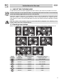
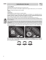
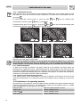
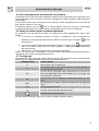
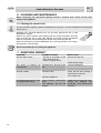
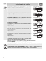
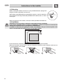
Table of contents
1.
INSTRUCTIONS FOR USE ______________________________________________ 18
2.
SAFETY INSTRUCTIONS _______________________________________________ 19
3.
BEFORE FIRST USE___________________________________________________ 20
4.
DESCRIPTION OF CONTROLS ON THE FRONT CONTROL PANEL ____________ 20
5.
USE OF THE COOKING HOB____________________________________________ 21
6.
CLEANING AND MAINTENANCE _________________________________________ 26
7.
SOMETHING WRONG? ________________________________________________ 26
8.
INSTALLATION _______________________________________________________ 27
INSTRUCTIONS FOR THE USER: these contain user advice, description of the commands and the
correct procedures for cleaning and maintenance of the appliance.
INSTRUCTIONS FOR THE INSTALLER: these are intended for the qualified technician who must
install the appliance, set it functioning and carry out an inspection test.
17
Instructions for use
1. INSTRUCTIONS FOR USE
ELECTRICAL CONNECTION: REFER TO THE INSTALLATION INSTRUCTIONS FOR THE SAFETY
REGULATIONS FOR ELECTRIC OR GAS APPLIANCES AND VENTILATION FUNCTIONS.
IN YOUR OWN INTEREST, AND THAT OF SAFETY, IT IS THE LAW THAT ALL GAS AND
ELECTRICAL APPLIANCES BE INSTALLED AND SERVICED BY COMPETENT PERSONS, WHO
WILL COMPLY WITH THE RELEVANT STANDARDS AND REGULATIONS.
OUR REGULAR INSTALLERS GUARANTEE A SATISFACTORY JOB.
GAS OR ELECTRIC APPLIANCES MUST ALWAYS BE DISCONNECTED BY SUITABLY SKILLED
PEOPLE.
THIS MANUAL IS AN INTEGRAL PART OF THE APPLIANCE AND THEREFORE MUST BE KEPT
IN ITS ENTIRETY AND IN AN ACCESSIBLE PLACE FOR THE WHOLE WORKING LIFE OF THE
HOB. WE ADVISE READING THIS MANUAL AND ALL THE INSTRUCTIONS THEREIN BEFORE
USING THE HOB. INSTALLATION MUST BE CARRIED OUT BY QUALIFIED PERSONNEL IN
ACCORDANCE WITH THE REGULATIONS IN FORCE. THIS APPLIANCE IS INTENDED FOR
DOMESTIC USES AND CONFORMS TO THE EEC DIRECTIVES CURRENTLY IN FORCE. THE
APPLIANCE HAS BEEN BUILT TO CARRY OUT THE FOLLOWING FUNCTIONS: COOKING AND
HEATING-UP OF FOOD. ALL OTHER USES ARE CONSIDERED IMPROPER.
THE MANUFACTURER DECLINES ALL RESPONSIBILITY FOR IMPROPER USE.
DO NOT DISCARD PACKING IN THE HOME ENVIRONMENT. SEPARATE THE VARIOUS WASTE
MATERIALS AND TAKE THEM TO THE NEAREST SPECIAL GARBAGE COLLECTION CENTRE.
THIS APPLIANCE IS MARKED ACCORDING TO THE EUROPEAN DIRECTIVE 2002/96/CE ON
WASTE ELECTRICAL AND ELECTRONIC EQUIPMENT – (WEEE).
THIS GUIDELINE IS THE FRAME OF A EUROPEAN-WIDE VALIDITY OF RETURN AND
RECYCLING ON WASTE ELECTRICAL AND ELECTRONIC EQUIPMENT.
DO NOT OBSTRUCT VENTILATION OPENINGS AND HEAT DISPERSAL SLITS.
THE IDENTIFICATION PLATE, WITH TECHNICAL DATA, SERIAL NUMBER AND MARKING IS
CLEARLY VISIBLE UNDER THE CASING. A COPY OF THE IDENTIFICATION PLATE IS
INCLUDED IN THE BOOKLET.
THE PLATE ON THE CASING MUST NOT BE REMOVED.
TAKE CARE NOT TO SPILL SUGAR OR SWEET MIXTURES ON TO THE HOB
WHEN HOT. NEVER PLACE MATERIALS OR SUBSTANCES WHICH MAY MELT
(PLASTIC OR ALUMINIUM FOIL) ON THE HOB. IN THE EVENT, PROMPTLY
SWITCH OFF AND REMOVE THE MOLTEN MATERIAL WITH THE SCRAPER
PROVIDED WHILE THE COOKING ZONE IS STILL WARM TO PREVENT IT
FROM BEING DAMAGED. FAILURE TO INSTANTLY CLEAN THE CERAMIC
HOB COULD LEAD TO ENCRUSTATIONS WHICH ARE IMPOSSIBLE TO
REMOVE ONCE THE HOB HAS COOLED DOWN.
The manufacturer declines all responsibility for damage to persons or things caused by nonobservance of the above prescriptions or by interference with any part of the appliance or by
the use of non-original spares.
18
Safety instructions
2. SAFETY INSTRUCTIONS
INSTRUCTIONS FOR THE INSTALLER: THESE ARE INTENDED FOR THE QUALIFIED
TECHNICIAN WHO MUST INSTALL THE APPLIANCE, SET IT FUNCTIONING AND CARRY OUT
AN INSPECTION TEST.
THE APPLIANCE MUST BE CONNECTED TO EARTH IN COMPLIANCE WITH ELECTRICAL
SYSTEM SAFETY REGULATIONS.
WHEN LINKING UP TO MAINS BY PLUG AND SOCKET, MAKE SURE THAT BOTH ARE
COMPATIBLE AND CONNECT BY MEANS OF A POWER CABLE COMPLYING WITH
APPLICABLE REGULATIONS.
THE SOCKET MUST BE ACCESSIBLE AFTER THE APPLIANCE IS BUILT IN.
NEVER UNPLUG BY PULLING ON THE CABLE.
ALWAYS CHECK THAT THE CONTROLS ARE IN THE POSITION "ZERO" (OFF) WHEN YOU
FINISH USING THE HOB.
DURING USE THE APPLIANCE BECOMES VERY HOT IN THE ZONE IN CONTACT WITH THE
PANS. TAKE CARE NOT TO TOUCH THE SURFACE OF THE HOB.
THE USE OF THIS APPLIANCE IS NOT PERMITTED TO PEOPLE (INCLUDING CHILDREN) OF
REDUCED PHYSICAL AND MENTAL ABILITY, OR LACKING IN EXPERIENCE IN THE USE OF
ELECTRICAL APPLIANCES, UNLESS THEY ARE SUPERVISED OR INSTRUCTED BY ADULTS
OR PEOPLE RESPONSIBLE FOR THEIR SAFETY.
AS SOON AS YOU NOTICE A FRACTURE OR A CRACK ON THE SURFACE OF THE CERAMIC
HOB, SWITCH THE APPLIANCE OFF AND CONTACT AN AUTHORISED TECHNICAL
ASSISTANCE CENTRE.
PEOPLE WHO HAVE PACEMAKERS OR OTHER SIMILAR DEVICES FITTED MUST MAKE SURE
THAT THE FUNCTIONING OF THESE DEVICES IS NOT JEOPARDISED BY THE INDUCTIVE
FIELD, WHOSE FREQUENCY RANGE IS BETWEEN 20 AND 50 KHZ.
THE APPLIANCE BECOMES VERY HOT DURING USE. SUITABLE HEAT-PROOF GLOVES
SHOULD BE WORN FOR ALL OPERATIONS.
BEFORE THE APPLIANCE IS PUT INTO OPERATION, ALL LABELS AND PROTECTIVE FILMS
APPLIED INSIDE OR OUTSIDE MUST BE REMOVED.
IMMEDIATELY AFTER INSTALLATION CARRY OUT A BRIEF INSPECTION TEST OF THE
APPLIANCE, FOLLOWING THE INSTRUCTIONS BELOW. SHOULD THE APPLIANCE NOT
FUNCTION, DISCONNECT IT FROM THE POWER SUPPLY AND CALL THE NEAREST
TECHNICAL ASSISTANCE CENTRE.
NEVER ATTEMPT TO REPAIR THE APPLIANCE. ALL REPAIRS MUST BE CARRIED OUT BY AN
AUTHORISED ENGINEER OR AT AN AUTHORISED SERVICE CENTRE.
IN CONFORMITY WITH THE PROVISIONS REGARDING ELECTROMAGNETIC COMPATIBILITY,
THE ELECTROMAGNETIC INDUCTION COOKING HOB COMES UNDER GROUP 2 AND CLASS B
(EN 55011)
Important!
Beware of children in the vicinity as the warning lights indicating residual heat are
out of sight to them (see paragraph “5.3.5 Residual heat”). In fact, even after having
been turned off, the cooking zone remains hot for a certain period of time. Make
sure that children never touch the hob.
19
Instructions for the user
3. BEFORE FIRST USE
Do not discard packing in the home environment. Separate the various waste materials and take them
to the nearest special garbage collection centre.
Remove all the REMOVABLE labels and any protective sheeting.
To switch on the hob, follow the instructions provided in paragraph “5 USE OF THE COOKING HOB”
4. DESCRIPTION OF CONTROLS ON THE FRONT CONTROL
PANEL
All the appliance's control and monitoring devices are placed together on the front panel. The symbols
used are described in the table below.
FRONT RIGHT-HAND COOKING
POWER INCREASE BUTTON TIMER
ZONE
INCREASE BUTTON
REAR RIGHT-HAND COOKING
ZONE
POWER DECREASE BUTTON
TIMER DECREASE BUTTON
FRONT LEFT-HAND COOKING
ZONE
LEVEL I POWER BUTTON
REAR LEFT-HAND COOKING
ZONE
LEVEL II POWER BUTTON
CENTRAL COOKING ZONE
LEVEL III POWER BUTTON
TIMER BUTTON
LEVEL TURBO INDUCTION BUTTON
COOKING ZONE LOCK-OUT
20
Instructions for the user
5. USE OF THE COOKING HOB
To operate the panel of the hobs equipped with touch-controls, press the icons printed on its surface.
On first connection to the electrical mains, an operating check will be carried out automatically
and all the indicator lights will come on for a few seconds.
Under each cooking zone there is a coil called an inductor which is powered by an electronic system
and which creates a variable magnetic field. When a pan is positioned within this magnetic field, the
high frequency currents are concentrated directly onto the pan producing the heat required for cooking
the food.
After use, switch off the hotplates using the controls described in paragraph “5.3.3 Switching off the
hotplate”. Never rely on the cookware detector.
5.1 Operating power settings
Below, we provide a table with the maximum power consumptions of the cooking zones that are on.
ZONE
NUMBER
ZONE
DIAMETER
MAX ABSORBED
POWER
ABSORBED POWER IN
POWER FUNCTION
160 mm
2000 W
Not available
210 mm
3100 W
Not available
280 mm
2800 W
Not available
280 mm
3200 W
3600
230 mm
2800 W
3100
160 mm
2000 W
2200
21
Instructions for the user
5.2 Cookware
Appliances of this type require special pans to be able to work.
In fact, the pan must have an iron bottom to generate the magnetic field necessary for it to be heated
up.
Recipients made of the following are not suitable:
1 glass;
2 ceramics;
3 earthenware;
4 steel, aluminium or copper without a magnetic bottom.
To see whether the pan is suitable, bring a magnet close to the bottom: if it is attracted, the pan is
suitable for induction cooking. If you do not have a magnet, you can put a small amount of water in the
recipient, place it on a cooking zone and start the hotplate. If the power symbol on the display starts to
flash, it means that the pan you are using is not suitable for your appliance.
The pans used for cooking must have a minimum diameter to guarantee proper functioning.
Metal objects such as cutlery or lids must not be left on the hob as they risk being overheated without
the user realising it.
Each cooking zone has an inner circle. This printed circle indicates the minimum permissible diameter
on that cooking zone. Pans with smaller diameters risk not being detected and therefore not activating
the inductor.
Pans that are larger than the cooking zones can also be used, but care must be taken that the bottom
of the pan does not come into contact with other cooking zone and that it is always centred on the
cooking zone perimeter.
Use only recipients with a perfectly flat bottom and which are suitable for induction cooking or, if
pans of this type are not available, recipients whose bottom is not crowned (concave or convex).
Using a pan with an irregular bottom could jeopardise the efficiency of the heating system so that the
pan is not detected on the hotplate.
YES
22
NO
NO
Instructions for the user
5.3 Switching on the cooking zone
Press the button for the cooking zone you want to use (for example
On the power display,0 appears. Pressing the keys
and
for the front right-hand zone).
you can set the power from 1 to 9.
Once you have set the hotplate's power level, this will not be activated until a pan suitable for
induction cooking is placed upon it. See paragraph 5.2 Cookware”
On the hotplates with keys
, the power level reaches 15.
If after having activating the hotplate, no power value is selected, the hotplate is automatically
deactivated.
5.3.1 Preselection levels (on some models only)
The keys
activated.
, present only on some models, allow preset power levels for that hotplate to be
Key
: cooking level 7;
Key
: cooking level 11;
Key
: cooking level 15;
5.3.2 POWER button (only on some models)
The key
,
present only on some models, permits supplementary power to be activated.
When it is pressed, the hotplate's power display will show
to indicate that the POWER function is
active on that hotplate. If the key
is pressed, a power setting of 15 will be set.
5.3.3 Switching off the hotplate
Any hotplate can be switched off (the figure shows the front right-hand zone) at any time by pressing
the ON/OFF key. The set power level will disappear from the display and if the hotplate remains hot
even after it has been switched off, a
begins to flash. On this regard, please refer to paragraph
“5.3.5 Residual heat”.
5.3.4 Automatic hotplate switch-off (on some models only)
By means of this function, present on some models only, it is possible to program the switching off of
the hotplate after a variable operating time: from 1 to 99 minutes.
1. Select the desired power level at which to use the hotplate;
and
the cooking duration can be set.
2. Using the keys
At the end of the time the hotplate will be deactivated and a buzzer will sound temporarily.
To interrupt the signal before time, press any button for the cooking plate used.
5.3.5 Residual heat
Each cooking zone is equipped with a residual heat warning device. After any zone is switched off, a
flashing “
”may appear on the display. This warns that the cooking zone concerned is still very hot.
Cooking can be restarted while the
is flashing: in this case, proceed as described in paragraph “3”.
23
Instructions for the user
5.3.6 Cooking hob lock-out
When the hob is on, it can be locked to avoid accidental modifications to the cooking values set. The
lock remains on even after the hob has been switched off. It is present only on the models that have
the symbol
.
To activate the lock, with the hob on, press the keys
simultaneously until the symbol
near the cooking zone
appears on the display.
To deactivate the lock, in the same way, press the
simultaneously until the symbol
and
and
keys near the locked cooking zone
disappears from the display.
The figure above shows the “grouping” of the cooking zones. When one hotplate is locked, the
hotplate in the same group is also locked.
Even when the hotplate is locked, it can be switched off pressing its ON/OFF key. In this case,
the lock is held until the next time it is switched on: to set a cooking level switching on a
locked hotplate, it must first be unlocked following the procedure as described in this section.
5.3.7 Power management
To optimise the energy consumption, the groups made up of two hotplates (see figure above) are
prevented from supplying more than a determined maximum operating power. If the value set for the
two hotplates exceeds the permitted power, the electronic circuit board will automatically maintain the
maximum level permitted modifying the power supplied by the hotplates. The power level selected by
the electronic circuit board will still be visible on the display.
5.3.8 Control circuit board thermal protection
If the cooking zones cause overheating of the internal electronic circuit board, the heat will be
switched off automatically. This switches off power to the hotplates and F7 will light up on the power
LEDs.
5.4 Limitations to the operating duration
The electronics of this appliance limit the cooking duration according to the power selected. After the
maximum time period has gone by, the cooking zone switches off, the appliance emits an audible
signal and AS(automatic stop) appears on the display.
Power level set
Maximum cooking duration in hours
Levels 1 to 9
8 hours' cooking at most
Levels 10 to 14
2 hours' cooking at most
Level 15 to
24
1 hour's cooking at most
Instructions for the user
5.5 Error messages from the electronic circuit board
The electronic circuit board has been designed to protect the hob components from malfunctions that
can damage them. For this purpose, some error messages have been provided, visible through the
power display.
If error codes from F1 to F9, should appear on the display, call the authorised service centre and tell
them the error code you have read.
and an acoustic BEEP is heard, it means that a metal object
If the display appears in this way
has been left inadvertently on the hob and that it could become hot if the hob is switched on.
5.6 Safety functions against accidental operations
To provide the user with the utmost safety, this appliance has been equipped with various safety
devices.
1) if two keys are accidentally pressed, no function is switched on. After 10 seconds, the
electronic circuit board will deactivate the product and some signs will appear
power displays;
on the
2) in the case in which the electronic circuit board continues to register a key
being pressed
after the maximum power level has been reached, a safety device will automatically
deactivate the hob;
3) after a drop in current the appliance is not automatically restarted;
Points 1) and 2) can occur, for example, in the case in which a pan has been badly positioned on the
cooking hob and it covers the hotplate ON/OFF keys.
5.7 Cooking tips
The table below shows the power values which can be set, with the relative type of food alongside.
Settings may vary depending on the amount of food and personal taste.
KNOB SETTING
TYPE OF FOOD
0
OFF position, use of residual heat
1-2
To heat food, keep small amounts of water on the boil, and whip up
sauces with egg yolk or butter.
3-6
To heat solid or liquid food, keep small amounts of water on the
boil, thaw deep-frozen food, cook omelettes of 2 or 3 eggs, fruit
and vegetables, and the like.
7-9
To stew meat, fish and vegetables, simmer food, make jams, and
so on.
10-11
To roast meat, fish, steaks, and liver; to sauté meat, fish, eggs and
so on.
12-14
To roast large cuts of meat
15
To roast, brown and cook large cuts of meat
POWER level (maximum power).
For best results and energy saving, only use pans suitable for electric cooking:
25
Instructions for the user
6. CLEANING AND MAINTENANCE
Before performing any operations requiring access to powered parts, switch off the power
supply to the appliance.
6.1 Cleaning the ceramic hob
The hob should be regularly cleaned; preferably after every use, once the residual heat warning lights
have gone off.
Smudges from aluminium-bottom pans can be easily cleaned off with a cloth
dampened in vinegar.
Remove any burnt residues after cooking with the scraper provided; rinse with
water and wipe dry with a clean cloth. Regular use of the scraper considerably
reduces the need for chemical detergents for the daily cleaning of the hob.
Never use abrasive or corrosive detergents (e.g. cleaning powders, oven sprays,
spot-removers, wire sponges).
Do not use a steam jet for cleaning the appliance.
7. SOMETHING WRONG?
PROBLEM
The hob doesn’t work.
POSSIBLE CAUSES
WHAT TO DO?
- The hob is not wired in or the - Switch on at the wall.
main switch is not on.
- There is a power failure.
- Check power supply.
The results of cooking are - Temperature is too high or too - Consult cooking tips.
unsatisfactory.
low.
The hob smokes.
- The hob is dirty.
- Clean the hob once cooking is
finished. Let it cool first.
- Use a larger pan.
- Food has spilled out.
The cooking zones do not come - Timed cooking programming - Check the instructions for timer.
on during timed cooking.
error.
- Unlock the hotplates (see
- The hotplates are off and paragraph “5.3.6 Cooking hob
locked.
lock-out”).
26
Instructions for the installer
8. INSTALLATION
8.1 Technical information
Hob type
Electrical connections
HOB RATING
Maximum electrical power
See rating plate
220-240V~ 50/60Hz / 380-415V 2N∼ 50/60Hz / 380-415V 3N∼ 50/60Hz
I
See rating plate
8.2 The rating plate
Make sure that the voltage and capacity of the power
line conform to the data shown on the plate located
under the casing. Do not remove this plate for any
reason.
Serial N°
Model
8.3 Electrical connection
THE APPLIANCE MUST BE CONNECTED TO EARTH IN COMPLIANCE WITH ELECTRICAL
SYSTEM SAFETY REGULATIONS.
WHEN LINKING UP TO MAINS BY PLUG AND SOCKET, MAKE SURE THAT BOTH ARE
COMPATIBLE AND CONNECT BY MEANS OF A POWER CABLE COMPLYING WITH APPLICABLE
REGULATIONS.
THE SOCKET MUST BE ACCESSIBLE AFTER THE APPLIANCE IS BUILT IN.
NEVER UNPLUG BY PULLING ON THE CABLE.
IMMEDIATELY AFTER INSTALLATION CARRY OUT A BRIEF INSPECTION TEST OF THE HOB,
FOLLOWING THE INSTRUCTIONS. IF THE HOB FAILS TO OPERATE, AFTER CHECKING THAT
YOU HAVE CARRIED OUT THE INSTRUCTIONS CORRECTLY, DISCONNECT THE APPLIANCE
FROM THE ELECTRICAL MAINS AND CONTACT YOUR NEAREST SERVICE CENTRE.
N VER ATTEMPT TO REPAIR THE APPLIANCE.
PASS THE POWER SUPPLY CABLE THROUGH THE BACK OF THE UNIT, TAKING CARE THAT IT
DOES NOT TOUCH THE BOTTOM CASING OF THE HOB OR THE OVEN (IF ANY) INSTALLED
UNDERNEATH IT.
IF A PLUG AND SOCKET CONNECTION IS BEING USED MAKE SURE THAT THE PLUG AND
SOCKET ARE COMPATIBLE. AVOID USE OF ADAPTERS AND SHUNTS AS THESE COULD
CAUSE OVERHEATING AND RISK OF BURNS.
IF A FIXED CONNECTION IS BEING USED FIT POWER LINE WITH AN OMNIPOLAR CIRCUIT
BREAKER WITH A CONTACT OPENING GAP EQUAL TO OR GREATER THAN 3 MM, IN AN
EASILY ACCESSIBLE POSITION IN PROXIMITY TO THE OVEN.
27
Instructions for the installer
For operation on 380-415 V 3N∼ : use an H05V2V2-F - type five-core
cable (5 x 1.5 mm2) heat-resistant to at least 90°C.
For operation on 380-415V 2N ∼: use an H05V2V2-F - type four-core
cable (4 x 1.5 mm2) heat-resistant to at least 90°C.
For operation on 220-240 V 3∼: use an H05V2V2-F - type four-core
cable (4 x 1.5 mm2) heat-resistant to at least 90°C.
For operation on 220-240V∼:
30 cm hobs: use an H05V2V2-F type three-core cable, heat-resistant to
at least 90°C.
(cable 3 x 1.5 mm2)
60-70 cm hobs: use an H05V2V2-F type three-core cable, heatresistant to at least 90°C.
(cable 3 x 4 mm2)
90 cm hobs use an H05V2V2-F type three-core cable, heat-resistant to
at least 90°C.
(cable 3 x 6 mm2)
The earth wire (yellow-green) must be at least 20 mm longer than the
other wires at the end for connection to the appliance.
Depending on the hob you have purchased, the possible electrical connections are:
30 cm hobs: 220-240V∼
60-70 cm hobs: 220-240V∼ / 220-240V 3 ∼ / 380-415V 2N ∼
90 cm hobs: 220-240V∼ / 220-240V 3 ∼ / 380-415V 2N ∼ / 380-415V 3N ∼
READ THE CONNECTION LAYOUT PLATE UNDERNEATH THE APPLIANCE OR AROUND THE
POWER CABLE WITH CARE.
The manufacturer declines all responsibility for damage to persons or things caused by nonobservance of the above prescriptions or by interference with any part of the appliance.
28
Instructions for the installer
8.4 Positioning of the hob
The following operation requires building and/or carpentry work so must be carried out by a
competent tradesman.
Installation can be carried out on various materials such as masonry, metal, solid wood or
plastic laminated wood as long as they are heat resistant (T 90°C).
Create an opening with the dimensions shown in the figure in the top surface of the counter,
keeping a minimum distance of 50 mm from the rear edge.
This appliance can be mounted against walls higher than the work surface on condition that a
distance of 110 mm be kept between the appliance and the wall as shown in the figure so as to
avoid damage from overheating.
Make sure there is a minimum of 750 mm between the hob and any shelf that may be installed
directly above it.
The dimensions indicated in the figure are the
same for all models without a frame.
Below is supplied the table of comparison between
the dimension Y to be created in the worktop and
the dimension X of the cooker hob.
DIMENSION X
DIMENSION Y
The dimensions indicated in the figure are the
same for all models with a frame.
Below is supplied the table of comparison between
the dimension K to be created in the worktop and
the dimension Z of the cooker hob.
DIMENSION Z
DIMENSION K
300
270
600
560
600
565
900
879
700
565
900
878
In case of installation on an empty kitchen unit with doors, a separation panel must be placed under the hob.
Keep a minimum distance of 20 mm between the bottom of the hob and the surface of the panel, which must be
easily extractable to allow sufficient access for any technical assistance.
29
Instructions for the installer
8.5 Mounting
Before mounting the device to the unit, lay the provided adhesive sponge onto
the glass surface to separate it from the unit.
After fixing the provided adhesive sponge (B) to the glass, mount the device to
the unit with the mounting brackets (A) provided with the device itself, as shown
in the figure.
When fixing the hob to the cabinet, use only the holes provided, illustrated here.
8.6 Ventilation
Installation of an oven without cooking fan underneath the hob is forbidden.
In any event, if installed above an oven or a dishwasher, a space of at least 5 cm must be left
between the hob and the top of the appliance installed below.
In addition to this, leave an opening of at least 4 mm between the top of the front panel of the
built-in oven beneath and the base of the hob (see figure below)
Do not obstruct the ventilation grille in front of the product in any type of installation
Below are illustrations of two cases (1 and 3) of installation suitable for correct ventilation and one case
(n° 2) of installation to be avoided
30