1
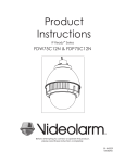
for
COMMUNICATIONS
MODEL: 25733, 25735, 35541, & 35540
PRODUCT INSTRUCTIONS
Before attempting to connect or operate this product,
please read these instructions completely.
81-IN6221R3
!
Electrical Specifications
Power 24VAC
Class 2 Only
24 VAC
3.7 Amps
89 Watts
English
Español
Français
Deutsch
25733, 25735
35541, 35540
Clear
Tinted
Accessories:
Camera Power:
Tools Required:
Heater: 50 Watts/Blower: 2 Watt
Up to 37 Watts
.100” Flat Head Screwdriver
Phillips Head Screwdriver
Note: 25735 includes no accessories
24 VAC
3.7 amperios
89 vatios
Accesorios:
Calentador: 50 Watts/Blower: 2 vatio
Energía De la Cámara fotográfica:
Up to 37 vatios
Las Herramientas Requirieron: Destornillador Principal Plano Del 100"
Destornillador Principal Phillips
Nota: 25735 no incluye ningún accesorio
24 VCA
3.7 ampères
89 watts
Accessoires :
Réchauffeur : 50 Watts/Blower : 2 watt
Puissance D'Appareil-photo :
Up to 37 watts
Les Outils besoin :
Tournevis Principal Plat De 100"
Tournevis Principal Phillips
Note : 25735 n'inclut aucun accessoire
24 VAC
3.7 Ampere
89 Watt
Zusatzgeräte:
Kamera-Energie:
Werkzeuge Erforderten:
Heizung: 50 Watts/Blower: 2 Watt
Up to 37 Watt
100"Flacher Hauptschraubenzieher
Kreuzkopfhauptschraubenzieher
Anmerkung: 25735 schließt keine Zusatzgeräte mit ein
24 VAC
3.7 ampères
89 watts
Acessórios:
Poder Da Câmera:
Calefator: 50 Watts/Blower: 2 watt
Up to 37 watt
Portuguese As Ferramentas Requereram: Chave de fenda Principal Lisa Do 100"
Chave de fenda Principal Phillips
Nota: 25735 não inclui nenhum acessório
24 VAC
3.7 ampère
89 watt
Italiano
Accessori:
Riscaldatore: 50 Watts/Blower: 2 watt
Alimentazione Della Macchina fotografica:
Up to 37 watt
Attrezzi Richiesti:
Cacciavite Capo Piano Del 100"
Cacciavite Capo "phillips"
Nota: 25735 non include accessori
25735 (INDOOR ONLY)
24 VAC
No power options provided.
Power required for camera only.
24 VAC
Ningunas opciones de la energía proporcionaron.
Energía requerida para la cámara fotográfica solamente.
24 VCA
Option de puissance n'a pas fourni.
Puissance requise pour l'appareil-photo seulement.
24 VAC
Keine Energie Wahlen stellten zur Verfügung.
Energie erfordert für nur Kamera.
24 VAC
Nenhumas opções do poder fornecidas.
Poder requerido para a câmera somente.
24 VAC
Nessun'opzione di alimentazione ha fornito.
Alimentazione richiesta per la macchina fotografica soltanto.
IMPORTANT SAFEGUARDS
1. Read Instructions - All the safety and operating instructions
SAFETY PRECAUTIONS
should be read before the unit is operated.
2. Retain Instructions - The safety and operating instructions
should be retained for future reference.
!
3. Heed Warnings - All warnings on the unit and in the operating
instructions should be adhered to.
4. Follow Instructions - All operating and user instructions should
be followed.
5. Electrical Connections - Only a qualified electrician should make
CAUTION: TO REDUCE THE RISK OF ELECTRICAL SHOCK,
DO NOT OPEN COVERS.
NO USER SERVICEABLE PARTS INSIDE.
REFER SERVICING TO QUALIFIED SERVICE PERSONNEL.
electrical connections.
6. Attachments - Do not use attachments not recommended by the
product manufacturer as they may cause hazards.
The lightning flash with an arrowhead symbol,
with in an equilateral triangle, is intended to alert the
user to the presence of non-insulated "dangerous
voltage" within the product's enclosure that may
be of sufficient magnitude to constitute a risk of
7. Cable Runs -All cable runs must be within permissible
distance.
8. Mounting - This unit must be properly and securely mounted to
a supporting structure capable of sustaining the weight of
the unit. Accordingly:
a. The installation should be made by a qualified installer.
b. The installation should be in compliance with local codes.
c. Care should be exercised to select suitable hardware to install the
unit, taking into account both the composition of the mounting
surface and the weight of the unit. Be sure to periodically
examine the unit and the supporting structure to make sure
that the integrity of the installation is intact. Failure to comply
with the foregoing could result in the unit separating from the
support structure and falling, with resultant damages or injury
to anyone or anything struck by the falling unit.
DOME/HOUSING/ELECTRICAL COMPONENT
WARRANTY INFORMATION
Axis, Incorporated warrants that its domes and housing
sold here under shall be fit for the ordinary purpose for which
said products are intended and shall be free from defects in
material and workmanship for a period of three years from date
of sale to buyer. Note that all electrical components will be
warranted for a period of three years from date of sale to buyer.
Axis makes no other warranty of any kind with respect
to this product, whether expressed or implied, including,
without limitation, the implied warranty of fitness for a particular
purpose.
In the event of a breach of the above warranty, Axis shall,
at its option, repair or replace said product. This is Axis's
C AUTION
R ISK OF
ELECTRIC SHOCK !
electric shock to persons.
!
The exclamation point with in an equilateral triangle
is intended to alert the user to presence of important
operating and maintenance (servicing) instructions
in the literature accompanying the appliance.
UNPACKING
Unpack carefully. Electronic components can be damaged if
improperly handled or dropped. If an item appears to have been
damaged in shipment, replace it properly in its carton and notify
the shipper.
Be sure to save:
1. The shipping carton and packaging material. They are the safest
material in which to make future shipments of the equipment.
2. These Installation and Operating Instructions.
SERVICE
If the unit ever needs repair service, the customer should contact
Axis (1-800-444-2947) for authorization to return and
shipping instructions.
TECHNICAL SUPPORT
If technical support is needed, Axis has set-up a technical support
line for their customers.
sole obligation under this warranty. In no event shall Axis
be liable for any incidental or consequential damages, as
defined in section 2-715 of the Uniform Commercial Code by a
breach of this warranty.
Axis shall repair or replace defective products upon
shipment of products returned prepaid to Axis.
AXIS TECHNICAL SUPPORT
1-800- 444-2947
Repairs made necessary by reason of accident, misuse or
normal wear shall be charged at Axis's standard rate.
This warranty gives you specific legal rights, and you may also
have other rights which vary from state to state.
1
2
Wrap Teflon tape around the pipe threads
to ensure a tight seal.
Securely mount bracket to wall. Pull wiring
through bracket and position grommet as shown.
• Con seguridad soporte del montaje a emparedar. Tire del cableado
a través del soporte y del ojal de la posición según lo demostrado.
• Solidement parenthèse de bâti à murer. Tirez le câblage par la
parenthèse et le canon isolant de position comme montré.
• Sicher Einfassung Haltewinkel wall. Ziehen Sie Verdrahtung durch
Haltewinkel und Position Gummimuffe, wie gezeigt.
• Firmemente suporte da montagem a wall. Puxe a fiação através do
suporte e do ilhó da posição como mostrado.
• Saldamente staffa del supporto da wall. Tiri i collegamenti tramite la
staffa ed il gommino di protezione di posizione come indicato.
TM
• La cinta del Teflon del abrigo alrededor de la pipa rosca
para asegurar un sello apretado.
• La bande de teflon d'enveloppe autour de la pipe filète
pour assurer un joint serré.
• Verpackung Teflonklebeband um das Rohr verlegt, um
eine feste Dichtung sicherzustellen.
• A fita adesiva do Teflon do envoltório em torno da
tubulação enfía para assegurar um selo apertado.
• Il nastro del Teflon dell'involucro intorno al tubo filetta per
accertare una guarnizione stretta.
4
3
Screw the coupling onto the pipe threads
until it is hand tight.
• Atornille el acoplador sobre los hilos de rosca de la pipa
hasta que es mano firmemente.
• Vissez le couplage sur les fils de pipe jusqu'à ce que ce
soit main fortement.
• Schrauben Sie die Koppelung auf die Rohrgewinde, bis
es Hand fest ist.
• Parafuse o acoplamento nas linhas da tubulação até
que esteja mão firmemente.
• Avviti l'accoppiamento sui filetti del tubo fino a che non
sia fortemente mano.
Screw the (2) bolts into the coupling.
• Atornille (2) los pernos en el acoplador.
• Vissez (2) les boulons dans l'accouplement.
• Schrauben Sie die (2) Schraubbolzen in die Koppelung.
• Parafuse (2) os parafusos no acoplamento.
• Avviti (2) i bulloni nell'accoppiamento.
5
Loop the lanyard over the set screw to
temporarily hold housing.
• Coloque el acollador sobre el tornillo de presión para
celebrar temporalmente la cubierta.
• Faites une boucle la lanière au-dessus de la vis de réglage
pour tenir temporairement le logement.
• Schlingen Sie die Abzuglinie über der Klemmschraube, um
Gehäuse vorübergehend zu halten.
• Dê laços no colhedor sobre o parafuso de fixação para
prender temporariamente a carcaça.
• Colleghi la cordicella in circuito sopra la vite di arresto
temporaneamente per tenere l'alloggiamento.
7
Undo the lanyard, pull housing up and twist
secure with the locking bolt and washers.
6
Make the appropriate wiring connections
from the dome to the pendant.
• Hacer las conexiones de cableado de la cúpula de la
pendiente.
• Faites le câblage de la coupole de la suspension.
• Nehmen Sie die entsprechenden Kabel-Verbindungen von der
Kuppel auf den Anhänger.
• Faça as conexões de cabos da cúpula para o pingente.
• Apportare le opportune connessioni cablaggio dalla cupola a
ciondolo.
8
Slide the grommet down over the coupling to prevent
water from entering and complete the assembly.
• Deshaga el acollador, tire de contener para arriba y tuerza seguro
con el perno y las arandelas de fijación.
• Resbale el ojal abajo sobre el acoplador para evitar que el agua
entre y para terminar a la asamblea.
• Défaites la lanière, tirez loger vers le haut et tordez bloqué avec le
boulon et les rondelles de fermeture.
• Glissez le canon isolant vers le bas au-dessus de l'accouplement
pour empêcher l'eau d'entrer et pour accomplir l'assemblée.
• Annulieren Sie die Abzuglinie, ziehen Sie oben unterbringen und
verdrehen Sie sicheres mit dem verriegelnschraubbolzen und den
Unterlegscheiben.
• Schieben Sie die Gummimuffe unten über der Koppelung, um zu
verhindern, daß Wasser und die Versammlung durchzuführen
hereinkommt.
• Undo o colhedor, puxe abrigar acima e torça seguro com o
parafuso e as arruelas travando.
• Deslize o ilhó para baixo sobre o acoplamento para impedir que a
água entre e para terminar o conjunto.
• Undo la cordicella, tiri l'alloggio in su e torca sicuro con il bullone e
le rondelle di bloccaggio.
• Faccia scorrere il gommino di protezione giù sopra l'accoppiamento
per impedire l'acqua entrare e per completare il complessivo.
9
RJ45
24VAC
1
2
3
4
Camera
Camera
Heater/Blower
Heater/Blower
POWER
Red
Orange
Yellow
Green
25 Watts
26 Watts
1/0
Alarm 1
Alarm 2
Alarm 3
Common
1
2
3
4
Blue
Violet
Gray
White
BNC
Make the appropriate male and female connections. Indoor model does not include pre-run cables.
• Haga las conexiones masculinas y femeninas apropiadas. El modelo de interior no incluye pre-funciona los cables.
• Établissez les rapports masculins et femelles appropriés. Le modèle d'intérieur n'inclut pas pré-courent des câbles.
• Stellen Sie die passenden männlichen und weiblichen Beziehungen her. Innenmodell schließt nicht vor-laufen lassen Kabel
ein.
• Faça as conexões masculinas e fêmeas apropriadas. O modelo indoor não inclui pre-funciona cabos.
• Faccia i collegamenti maschii e femminili adatti. Il modello dell'interno non include pre-fa funzionare i cavi.
10
11
Green
Yellow
Accessory
Power
Wire Gauge
5.5
10
20
30
Orange
Camera
Power
Red
,5
22
Total vA
consumed
40
50
60
70
80
ft
,75
20
1,0
18
1,5
16
2,5
14
400
m
120
600
960
121
182
292
180
300
480
800
4
12
6
10
-
-
2
MM
AWG
1300
36.5
54.9
91.4
146
243
396
86
141
225
358
571
905
1440
27.1
43.0
68.6
109
174
275
438
65
90
130
225
350
525
830
19.8
27.4
39.6
68.6
106
160
252
44
70
112
179
285
452
720
13.4
21.3
34.1
54.6
86.9
138
219
56
90
143
228
362
576
35
10.6
17.1
27.4
43.6
69.5
110
175
29
47
75
119
190
301
480
9.4
14.3
22.9
36.2
57.9
91.7
146
40
64
102
163
258
411
8.8
12.2
19.5
31.1
49.7
78.6
125
34
55
85
140
215
340
25
31
7.6
10.3
16.8
25.9
42.7
65.5
103
Camera = red & orange wires to terminal
Heater/Blower = yellow & green wires to terminal
These are recommended maximum distances
for 24VAC with a 10% voltage drop.
• Cámara fotográfica = alambres rojos y anaranjados al
terminal Heater/Blower = alambres del amarillo y del verde
al terminal
• Appareil-photo = fils rouges et oranges à la borne
Heater/Blower = fils de jaune et de vert à la borne
• Kamera = rote u. orange Leitungen zum Anschluß
Heater/Blower = Gelb- u. Grünleitungen zum Anschluß
• Câmera = fios vermelhos & alaranjados ao terminal
Heater/Blower = fios do amarelo & do verde ao terminal
• Macchina fotografica = legare rossi & arancioni al terminale
Heater/Blower = legare di verde & di colore giallo al terminale
• Éstos se recomiendan las distancias máximas para
24VAC con una caída de voltaje del 10%.
• Ceux-ci sont recommandés des distances maximum
pour 24VAC avec une chute de tension de 10%.
• Diese werden maximale Abstände für 24VAC mit
einem 10% Spannungsabfall empfohlen.
• Estes são recomendados distâncias máximas para
24VAC com uma queda de tensão de 10%.
• Questi sono suggeriti distanze massime per 24VAC con
una differenza de potenziale di 10%.
17
12
Axis 213
(3) #8x3/8”
(13mm) ½"
Mounting Plate
(26mm) 1"
Captive
Screw
(52mm) 2"
MOUNTING HOLE
Install the camera to the mounting plate with (2) #10 screws and lock washers provided. Place (3)
#8x3/8” screws on the spacers and align the mounting slots. Slide on plate and camera then secure.
• Instale la cámara fotográfica a la placa de montaje con (2) los tornillos #10 y las arandelas de cerradura proporcionadas. Coloque los
tornillos de (3) del # 8x3/8"en los espaciadores y alinee las ranuras de montaje. Resbale en la placa y la cámara fotográfica entonces
seguras.
• Installez l'appareil-photo sur le plat de support avec (2) les vis #10 et les rondelles de freinage fournies. Placez les vis de (3) # de 8x3/8"
sur les entretoises et alignez les fentes de support. Glissez du plat et de l'appareil-photo puis bloqués.
• Bringen Sie die Kamera zur Montageplatte mit (2) den bereitgestellten Schrauben #10 und Federringen an. Setzen Sie (3) # 8x3/8"die
Schrauben auf die Distanzscheiben und richten Sie die Befestigungsschlitze aus. Schieben Sie auf die sichere Platte und Kamera dann.
• Instale a câmera à placa de montagem com (2) os parafusos #10 e as arruelas de fechamento fornecidas. Coloque os parafusos de
(3) # de 8x3/8"nos espaçadores e alinhe os entalhes de montagem. Deslize na placa e na câmera então seguras.
• Installi la macchina fotografica al giunto di supporto con (2) le viti #10 e le ranelle di bloccaggio fornite. Disponga le viti di 8x3/8"# di (3)
sui distanziatori ed allinei le scanalature di montaggio. Faccia scorrere sulla piastra e sulla macchina fotografica allora sicure.
18
13
Axis 214
2685 Mounting
Plate
(3) #8 x 3/8”
Mounting Hole
(52mm) 2"
Mounting
Hole
Mounting
Hole
Captive
Screw
Install the camera to the mounting plate using (3) 3mm x 12mm bolts and lock washers. Place (3) #8x3/8”
screws on the spacers and line up the mounting slots. Slide plate in and secure.
• Instale la cámara fotográfica a la placa de montaje usando (3) los pernos de 3m m x de 12m m y las arandelas de cerradura.
•
•
•
•
Coloque los tornillos de (3) del # 8x3/8"en los espaciadores y alinee las ranuras de montaje. Resbale la placa adentro y
asegúrela.
Installez l'appareil-photo sur le plat de support en utilisant (3) des boulons de 3mm x de 12mm et des rondelles de freinage.
Placez les vis de (3) # de 8x3/8"sur les entretoises et alignez les fentes de support. Glissez le plat dedans et le fixez.
Bringen Sie die Kamera zur Montageplatte mit (3) 3mm x 12mm den Schraubbolzen und den Federringen an. Setzen Sie (3) #
8x3/8"die Schrauben auf die Distanzscheiben und richten Sie die Befestigungsschlitze aus. Schieben Sie Platte innen und sichern
Sie.
Instale a câmera à placa de montagem usando (3) os parafusos de 3mm x de 12mm e as arruelas de fechamento. Coloque os
parafusos de (3) # de 8x3/8"nos espaçadores e alinhe-os acima dos entalhes de montagem. Deslize a placa dentro e fixe-a.
Installi la macchina fotografica al giunto di supporto usando (3) i bulloni di 12mm x di 3mm e le ranelle di bloccaggio. Disponga
le viti di 8x3/8"# di (3) sui distanziatori ed allinei le scanalature di montaggio. Faccia scorrere la piastra dentro e fissi.
14
Axis 215
1"
1"
2"
Mounting Holes
Attach camera to quick release plate as shown. Use spacers to assemble (4) 3” legs. Secure
camera into position.
• Una la cámara fotográfica a la placa rápida del lanzamiento según lo demostrado. Utilice los espaciadores para
montar (4) las piernas del 3". Asegure la cámara fotográfica en la posición.
• Attachez l'appareil-photo au plat rapide de dégagement comme montré. Employez les entretoises pour assembler (4) des jambes de 3". Fixez l'appareil-photo en l'place.
• Bringen Sie Kamera zur schnellen Freigabeplatte an, wie gezeigt. Benutzen Sie Distanzscheiben, um (4) die 3"Beine
zusammenzubauen. Sichern Sie Kamera in Position.
• Una a câmera à placa rápida da liberação como mostrada. Use espaçadores montar (4) os pés de 3". Fixe a
câmera na posição.
• Fissi la macchina fotografica alla piastra rapida del rilascio come indicata. Usi i distanziatori per montare (4) i
piedini di 3". Fissi la macchina fotografica nella posizione.
15
AXIS 231-232D
Tab
16
AXIS 231-232D
TAB
Locking screw
Loosen
Screw
Loosen the screw to the right of the tab by
approximately (5) turns.
Align mounting plate and turn counterclockwise, secure locking screw.
• Afloje el tornillo a la derecha de la lengüeta aproximadamente (5) vueltas.
• Desserrez la vis à la droite de l'étiquette approximativement (5) aux tours.
• Lösen Sie die Schraube auf der rechten Seite des
Vorsprunges durch ungefähr (5) Umdrehungen.
• Afrouxe o parafuso à direita da aba aproximadamente (5) por voltas.
• Allenti la vite alla destra della linguetta circa (5) dalle
girate.
• Alinee la placa de montaje y dé vuelta a la
izquierda, tornillo de fijación seguro.
• Alignez le plat de support et tournez dans le sens
contraire des aiguilles d'une montre, vis de blocage
bloquée.
• Richten Sie Montageplatte aus und drehen Sie nach
links, sichere Sicherungsschraube.
• Alinhe a placa de montagem e gire-a no sentido
anti-horário, parafuso travando seguro.
• Allinei il giunto di supporto e giri in senso antiorario, la
vite di bloccaggio sicura.
20
17
Connection
Module
3mm
Screw
Power
Board
To
remove
thethe
power
board,path
use screwdriver
to release
fasteners
applying
to sides while pulling out.
This
is what
typical
of illumination
willplastic
look like
withby
the
settingpressure
at 30 degrees.
Attach connection module as shown. Attach this assembly to the housing using (1) 6-32x3/8” screw and star washer.
• Para quitar al tablero de energía, utilice el destornillador para lanzar los sujetadores plásticos aplicando la presión a los lados mientras que se saca.
Una el módulo de la conexión según lo demostrado. Una a esta asamblea a la cubierta usando (1) "arandela del tornillo 6-32x3/8 y de la estrella.
• Pour enlever carte d'alimentation, utilisez le tournevis pour libérer les attaches en plastique en s'appliquant la pression aux côtés tout en retirant.
Attachez le module de raccordement comme montré. Attachez cette assemblée au logement en utilisant (1) la "vis 6-32x3/8 et tenez le premier rôle
la rondelle.
• Um das Energie Brett zu entfernen, benutzen Sie Schraubenzieher um Plastikbefestiger freizugeben indem Sie anwenden Druck an den Seiten beim
Ausziehen. Bringen Sie Anschlußmodul an, wie gezeigt. Bringen Sie diese Versammlung zum Gehäuse mit (1) "Schraube 6-32x3/8 und Sternunterlegscheibe an.
• Para remover a placa de poder, use a chave de fenda liberar prendedores plásticos aplicando a pressão aos lados ao retirar. Una o módulo da
conexão como mostrado. Una este conjunto à carcaça usando (1) do "arruela parafuso 6-32x3/8 e da estrela.
• Per rimuovere il bordo di alimentazione, utilizzi il cacciavite per liberare i fermi di plastica applicando la pressione ai lati mentre estraggono. Fissi il
modulo del collegamento come indicato. Fissi questo complessivo all'alloggiamento usando (1) "rondella della vite 6-32x3/8 e della stella.
21
18
Open Screw
Slots
Cable
Ties
POWER
1
Camera Power (24VAC)
Red
2
Camera Power (24VAC)
Orange
CONTROL
RJ45 Ethernet Connector
ALARMS
1
Alarm 1
Blue
2
Alarm 2
Violet
3
Alarm 3
Gray
4
Common
White
Captive
Screw
Complete
thetypical
wiring
to of
camera.
Attach
thelike
camera
the housing by sliding the (3)
This is what the
path
illumination
will look
with the assembly
setting at 30 to
degrees.
open screw slots over the screws in the housing; tighten the fasteners on the bracket.
• Termine el cableado a la cámara fotográfica. Una el montaje de la cámara fotográfica a la cubierta resbalando
(3) las ranuras abiertas del tornillo sobre los tornillos en la cubierta; apriete los sujetadores en el soporte.
• Accomplissez le câblage à l'appareil-photo. Attachez l'appareil-photo au logement en glissant (3) les fentes
ouvertes de vis au-dessus des vis dans le logement ; serrez les attaches sur la parenthèse.
• Führen Sie die Verdrahtung zur Kamera durch. Bringen Sie die Kamera zum Gehäuse an, indem Sie die (3) geöffneten Schraube Schlitze über den Schrauben im Gehäuse schieben; ziehen Sie die Befestiger am Haltewinkel fest.
• Termine a fiação à câmera. Una o conjunto da câmera à carcaça deslizando (3) os entalhes abertos do parafuso
sobre os parafusos na carcaça; aperte os prendedores no suporte.
• Completi i collegamenti alla macchina fotografica. Fissi il complessivo della macchina fotografica all'alloggiamento
facendo scorrere (3) le scanalature aperte della vite sopra le viti nell'alloggiamento; stringa i fermi sulla staffa.
19
20
Camrea Specification
Camera
Power
Camera Power (at 24VAC REQUIRED)
213
24W
at
12VDC 37W
at
24VAC
214
14W
at
12VDC 20W
at
24VAC
215
14.5W
at
12VDC 20W
at
24VAC
231/232 25W
at
19-20VAC 25W
at
24VAC
233
at
18-30VAC 25W
at
24VAC
25W
CAMERA POWER
Camera specification for 24VAC outdoor housing.
No electronics are included with indoor unit.
• Especificación de la cámara fotográfica para la cubierta
al aire libre 24VAC. No se incluye ninguna electrónica con
la unidad de interior.
• Spécifications d'appareil-photo pour le logement 24VAC
extérieur. Aucune électronique ne sont incluses avec
l'unité d'intérieur.
• Kameraspezifikation für im Freiengehäuse 24VAC. Keine
Elektronik sind mit Innenmaßeinheit eingeschlossen.
• Especificação da câmera para a carcaça 24VAC ao ar
livre. Nenhuma eletrônica é incluída com unidade indoor.
• Specifica della macchina fotografica per alloggiamento
esterno 24VAC. Nessun'elettronica è inclusa con l'unità
dell'interno.
21
POWER PLUG
For 12VDC unit connect power plug and
ethernet cables into camera.
• Para la unidad 12VDC conecte los cables del enchufe
y de Ethernet de energía en cámara fotográfica.
• Pour l'unité 12VDC reliez les câbles de prise et
d'Ethernet de puissance dans l'appareil-photo.
• Für Maßeinheit 12VDC schließen Sie Netzstecker- und
Ethernet-Kabel in Kamera an.
• Para a unidade 12VDC conecte cabos do plugue e
do Ethernet de poder na câmera.
• Per l'unità 12VDC colleghi i cavi della spina e di
Ethernet di alimentazione nella macchina fotografica.
22
ALARMS
24VAC INPUT
1
Alarm 1
Blue
2
Alarm 2
Violet
3
Alarm 3
Gray
4
Common
White
24VAC
24VAC units connect Red and Orange 24VAC
leads into camera power connectors.
• Las unidades 24VAC conectan los plomos rojos y anaranjados 24VAC en los conectadores de energía de la cámara
fotográfica.
• Les unités 24VAC relient les fils rouges 24VAC et oranges dans
des connecteurs de puissance d'appareil-photo.
• Maßeinheiten 24VAC schließen die roten und orange
Leitungen 24VAC in Kameraenergie Stecker an.
• As unidades 24VAC conectam as ligações 24VAC vermelhas
e alaranjadas em conectores de poder da câmera.
• Le unità 24VAC collegano i cavi rossi ed arancioni 24VAC nei
connettori di alimentazione della macchina fotografica.
For all cameras, 4 additional leads are provided
for alarm outputs.
• Para todas las cámaras fotográficas, 4 plomos adicionales se
proporcionan para las salidas del alarmar.
• Pour tous les appareils-photo, 4 fils additionnels sont donnés
pour des sorties d'alarme.
• Für alle Kameras werden 4 zusätzliche Leitungen für Warnung
Ausgänge zur Verfügung gestellt.
• Para todas as câmeras, 4 ligações adicionais são fornecidas
para saídas do alarme.
• Per tutte le macchine fotografiche, 4 cavi supplementari
sono forniti per le uscite dell'allarme.
23
Axis 233D
Remove power board. Use secrewdriver to release plastic fasteners by applying pressure to
sides while pulling out. Construct mounting bracket assembly and attach camera.
• Quitar poder bordo. Uso de liberar secrewdriver Sujetadores de plástico mediante la aplicación de presión a los
lados Mientras tira. Construir soporte de montaje Asamblea y adjuntar cámara.
• Retirer pouvoir bord. Utilisez secrewdriver à libérer Attaches en plastique en appliquant une pression à côtés Tout
en tirant. Construire support de montage Assemblage et joindre caméra.
• Entfernen Macht. Verwenden Sie zur Freigabe secrewdriver Kunststoff-Verschlüsse durch die Ausübung von Druck
auf Seiten Beim Herausziehen. Construct Montagebügel Montage-und Kamera befestigen.
• Remover poder embarcar. Use secrewdriver para liberação Plástico fixadores, aplicando pressão aos lados
Enquanto puxando para fora. Construir montagem Braçadeira Montagem e anexar câmera.
• Rimuovere il potere bordo. Utilizzo di rilasciare secrewdriver Fissaggi di plastica da applicare pressione per le parti
Mentre tirando. Costruisci staffa di montaggio Assemblea e allegare fotocamera.
24
Axis 233D
Locking Screw
1/2” / 12.5mm Spacer
Secure quick release plate. Slide camera into position using keyhole slots. Tighten thumb
screw.
• Asegure la placa rápida del lanzamiento. Resbale la cámara fotográfica dentro de la posición usando ranuras del
ojo de la cerradura. Apriete el tornillo de pulgar.
• Fixez le plat rapide de dégagement. Glissez l'appareil-photo en l'place en utilisant des fentes de trou de la serrure.
Serrez la vis de pouce.
• Sichern Sie schnelle Freigabeplatte. Schieben Sie Kamera in Position mit Schlüssellochschlitzen. Ziehen Sie Rändelschraube fest.
• Fixe a placa rápida da liberação. Deslize a câmera na posição usando entalhes do buraco da fechadura. Aperte
o parafuso de polegar.
• Fissi la piastra rapida del rilascio. Faccia scorrere la macchina fotografica nella posizione usando le scanalature
del buco della serratura. Stringa la vite di pollice.
17
25
Axis P5534
(3) #8x3/8”
(13mm) ½"
Axis Locking Plate
(26mm) 1"
Quick Release Plate
Captive
Screw
Mounting Bracket
MOUNTING HOLE
Assemble Axis locking plate to quick release plate using (3) #8 bolts, washers and nuts. Connect the combined plates to
the bracket and housing using (4) 1” and (4) ½” spacers and #8 bolts. Insert camera onto mounted locking plate and turn
clockwise to lock in position.
•
•
•
•
•
Monte la placa de fijación del eje la placa del lanzamiento rápido usando (3) los pernos #8, las arandelas y las tuercas. Conecte las placas combinadas con el
soporte y la cubierta usando (4) los espaciadores de 1” y (4) ½” y los pernos #8. Inserte la cámara sobre la placa de fijación montada y dé vuelta a la derecha a la
cerradura en la posición.
Assemblez le plat de verrouillage d'axe au plat de dégagement rapide utilisant (3) les boulons #8, les rondelles et les écrous. Reliez les plats combinés à la parenthèse
et au logement utilisant (4) les entretoises de 1 » et (4) ½ » et les boulons #8. Insérez l'appareil-photo sur le plat de verrouillage monté et tournez dans le sens des
aiguilles d'une montre pour fermer à clef en position.
Bauen Sie Verriegelungsplatte der Mittellinie zur Platte der schnellen Freigabe unter Verwendung (3) der Schraubbolzen #8, der Unterlegscheiben und der Nüsse
zusammen. Schließen Sie der kombinierten Platten an den Haltewinkel und das Gehäuse unter Verwendung (4) 1“ und (4) ½“ der Distanzscheiben und der
Schraubbolzen #8 an. Setzen Sie Kamera auf angebrachte Verriegelungsplatte ein und wenden Sie sich nach rechts an Verschluss in Position.
Monte a placa de travamento da linha central à placa da liberação rápida usando (os parafusos 3) #8, as arruelas e as porcas. Conecte as placas combinadas ao
suporte e à carcaça usando (4) espaçadores de 1” e (4) ½” e parafusos #8. Introduza a câmera na placa de travamento montada e gire-a no sentido horário para
o fechamento em posição.
Monti il piatto di chiusura di asse a usando del piatto del rilascio rapido (3) bulloni #8, rondelle e dadi. Colleghi i piatti uniti a usando dell'alloggiamento e della staffa
(4) i distanziatori del 1„ e (4) ½„ e bulloni #8. Inserisca la macchina fotografica sul piatto di chiusura montato e giri in senso orario verso la serratura nella posizione.
26
27
Before
Tab
After
Loop the lanyard around the tab inside the
housing.
Align the arrows on the outside of the dome
and lock.
• Coloque el acollador alrededor de la lengüeta
dentro de la cubierta.
• Faites une boucle la lanière autour de l'étiquette à
l'intérieur du logement.
• Schlingen Sie die Abzuglinie um den Vorsprung
innerhalb des Gehäuses.
• Dê laços no colhedor em torno da aba dentro da
carcaça.
• Colleghi la cordicella in circuito intorno alla
linguetta all'interno dell'alloggiamento.
• Alinee las flechas en el exterior de la bóveda y
trábese.
• Alignez les flèches sur l'extérieur du dôme et
fermez à clef.
• Richten Sie die Pfeile auf der Außenseite der
Haube aus und verriegeln Sie sich.
• Alinhe as setas na parte externa da abóbada e
trave-as.
• Allinei le frecce sulla parte esterna della cupola e
blocchi.
28
Fasten down the dome with a Phillips screwdriver.
• Sujete abajo de la bóveda con un destornillador Phillips.
• Attachez en bas du dôme avec un tournevis Phillips.
• Befestigen Sie sich hinunter die Haube mit einem
Kreuzkopfschraubenzieher.
29
Wipe the dome clean.
• Limpie la bóveda limpia.
• Essuyez le dôme.
• Wischen Sie die Haube sauber ab.
• Prenda abaixo a abóbada com uma chave de fenda
Phillips.
• Limpe a abóbada limpa.
• Fissisi giù la cupola con un cacciavite "phillips".
• Asciughi la cupola.
Replacement Parts List
15
25733
14
9
8
11
7
10
4
6
5
3
2
1
Part Number
Description
1
RPFD7501
Lower Trim Ring (Long)
2a
RCTFD7
Tinted Replacement Capsule
2b
RCFD7
Clear Replacement Capsule
3
RPFD703
Dome Clamping Bracket
4
RPFD072
24 Vac Heater
5
RPFD080
(12 Vdc) Blower (Used In 24v Housings)
6
RPFD060
Camera Bracket
7
RPRH707
Connection Pcb
8
RPFD040
Housing Hardware
9
RPFD709
Housing Top
10
RPNET02
Network Housing Power Board
11
RP46PKH2095
Network Camera Bracket
14
SD0160
Pendant Coupling Kit
15
SD0170
Quick Release Pipe Coupling
Hardware Packet
N/S
RP46PKH2094
N/S
RPPKE1100
Electrical Packet
N/S
RPTRAN100
120Vac-24Vac, 100VA or 96VA Transformer