1
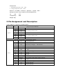
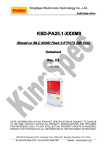
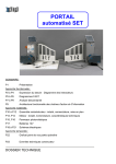
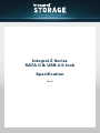
T E C H N I C A L D ATA S H E E T
Integral Z Series
SATA II & USB 2.5 Inch
Specification
Rev.H
1. Features
Supports 1.5/3.0Gbps SATA I/II interface
Fully Compliant with Serial ATA International Organization: Serial
ATA Revision 2.6 Fully Compliant with ATA/ATAPI-7 Standard
Capacities
Item
Mechanical Height
2.5inch (MLC)
9.3mm
Capacities
32GB, 64GB, 128GB, 256GB
Performance
Read
32GB
64GB
128GB
256GB
Write
150 MB/s*
38 MB/s*
160 MB/s*
70 MB/s*
160 MB/s*
70 MB/s*
160 MB/s*
70 MB/s*
(*sequential speeds listed are based on internal testing. Actual performance may vary based on
your system settings).
High reliability based on the internal BCH 10bit ECC
Supports
SMART
(Self-Monitor
Analysis
and
Reporting Technology)
Supports Dynamic and Static Wear Leveling
Supports MLC NAND
Flash Data integrity under power cycling MTBF >
2,000,000 Hours
Power
Consumption
<
1.75W @ 5V Seek time is
0.1ms~0.2ms
Shock
i.
Operating: 1,500G, duration 0.5ms, half sine wave
Vibration
i.
Vibration: 20G peak, (Random, 10~2KHz with 3 vibration axis)
ii.
Random Vibration
1.
7~800 Operating: 2.1Grms
2.
5~500 Non-Operating: 3.0Grms
Humidity: 0°C~55°C / 95% RH, 10cycles
Temperature
i.
ii.
Operating Temperature: -10°C ~ +70°C
Storage Temperature: -55°C ~ +95°C
External
mini-USB
connector
(optional)
support
Mass
Storage Function Fully Compliant with RoHS directive
CE
and
FCC
compatibility
SSD
Weight: 98g
2. Pin Assignment and Description
2.5inch SSD pin assignment and description
No.
Signal
Plug Connector pin definition
S1
GND
S2
A+
S3
A-
S4
GND
S5
B-
S6
B+
S7
GND
2
nd
mate
Differential signal A from PHY
2
nd
mate
Differential signal B from PHY
2
nd
mate
Key and spacing separate signal and power segments
P1
V33
3.3V power (Unused)
P2
V33
3.3V power (Unused)
P3
V33
3.3V power, pre-charge, 2
P4
P5
Power
GND
GND
st
1
2
mate
2
nd
mate
P6
GND
P7
V5
5V power, pre-charge, 2
P8
V5
5V power
P9
V5
5V power
P10
GND
P11
DAS/DSS
P12
GND
P13
V12
12V power, pre-charge, 2
P14
V12
12V power (Unused)
P15
V12
12V power (Unused)
nd
mate (Unused)
mate
nd
2
nd
nd
mate
mate
Device Activity Signal / Disable Staggered Spinup
st
1
mate
nd
mate (Unused)
4. Electrical Specification
Absolute Maximum Rating
Mi
n
Max
Unit
AV DDH
-0.5
6
V
DV DD
-0.5
6
V
Digital I/O input voltage
VI(D)
-0.4
DVDD + 0.4
V
Storage temperature
TStorage
-55
95
°C
Parameter
Analog power supply
Digital I/O power
supply
Symbol
Condition
Recommanded Power Supply Operation
Conditions
Parameter
Symbol
Operation digital power supply
Operation analog power
supply
Ambient operation
temperature
Junction temperature
Condition
Min
Typical
Max
Unit
DV DD
3.0
3.3
3.6
V
AVDDH
3.0
3.3
3.6
V
TA
-10
70
°C
TJ
-10
95
°C
Max
Unit
Recommanded External Clock Source Conditions
Parameter
Symbol
Condition
Min
External reference clock
Typical
30
Clock Duty Cycle
MHz
45
50
55
%
Min
Typical
Max
Unit
Power Supply DC Characteristics
(Idle)
Parameter
Digital I/O power supply
Internal digital power
supply
SATA analog power
supply
SATA analog power
supply
Symbol
Condition
IDVDD
3.3v
9
mA
IDDH_VR
1.8v
88
mA
IAVDDH_SATA
3.3v
41
mA
IAVDDH_SATA
1.8v
87
mA
Symbol
Condition
I/O DC Characteristics
Parameter
Min
Typical
Max
Unit
0.8
V
Input low voltage
VIL
Input high voltage
VIH
2.0
Output low voltage
VOL
0
0.4
V
Output high voltage
VOH
2.6
3.6
V
V
5. Physical Dimensions
2.5inch (99.88mm x 69.963mm x 9.3mm)