1
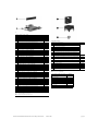
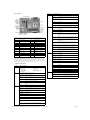
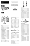
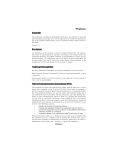
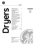
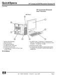
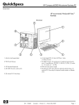
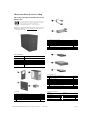
Illustrated Parts & Service Map
HP Compaq dx2300 and dx2308 Microtower
Business PC
© 2007 Hewlett-Packard Development Company, L.P. The information contained herein is subject to change without notice. HP shall not be liable for
technical or editorial errors or omissions contained herein.
Document Number 443233-001.
1st Edition February 2007.
NOTE: The part numbers listed here may not be the most current
information available. See http://partsurfer.hp.com for the most
current spare parts listing.
Cables
1
SATA cable, 10-in. (use for HDD)
392307-001
1
SATA cable, 13-in. (use for 2nd ODD)
391738-001
1
SATA cable, 14-in. (use for 1st ODD)
391740-001
2
Diskette drive cable
392288-001
*
Front USB cable with mounting screw
436328-001
*
Power switch with cable and switch mounting bracket
416163-001
*
Second serial port cable
444656-001
*
DMS 59 to Dual VGA adapter
339257-001
*Not shown
Key Specifications
Processor Type:
Intel Celeron D, Intel Pentium 4, Intel Pentium D, and Intel
Core 2 Duo
RAM Type:
DDR PC2-5300 non-ECC
Maximum RAM Supported:
2 GB
Expansion Bus:
PCI 2.3, PCI Express Gen 1
Graphics Adapter:
Integrated controller. PCI-Ex16 (max 75W).
Hard drive interface:
SATA 3.0 Gb/s
I/O Interfaces:
Serial (1), parallel (1), USB 2.0 (6), RJ-45 (1), front audio
jacks (2), rear audio jacks (3), P/S2 (2), VGA (1), and serial (2
optional)
Spare Parts
Mass Storage Devices
1
Diskette drive, 3.5-inch, with mounting screws
392415-001
2
48X SATA CD-ROM drive
419635-001
*
52X SATA CD-ROM drive
419469-001
*
16X SATA DVD-ROM drive
419496-001
*
16X SATA DVD R/W drive
419498-001
*
48/32 SATA DVD-ROM/CD-RW drive
419497-001
3
80-GB\7200 RPM SATA hard drive, 3.0 Gb/s
440754-001
*
160-GB\7200 RPM SATA hard drive, 3.0 Gb/s
440499-001
*
250-GB\7200 RPM SATA hard drive, 3.0 Gb/s
440747-001
*
Media card reader
407187-001
*Not shown
Keyboards (not illustrated)
System Unit
PS/2, Basic
USB, Basic
382925-xxx
382926-xxx
1
Front bezel without bezel blank (dx2300)
438609-001
*
Front bezel without bezel blank (dx2308 for China only)
445366-001
French Canadian
-121
PRC
-AA1
2
Access panel
440197-001
International
-B31
Taiwanese
-AB1
3
Chassis
not spared
Korean (Hanguel)
-AD1
Thai
-281
4
Power supply, PFC, 250W
441390-001
LA Spanish
-161
U.S.
-001
*
Power supply, non-PFC, 250W
444813-001
*Not shown
dx2300, dx2308 Illustrated Parts & Service Map, MT Chassis
443233-001
page 1
Standard and Optional Boards
Memory modules, non-ECC, DDR2
1
256 MB, PC2-5300, CL5
396519-001
*
512 MB, PC2-5300, CL5
396520-001
*
1 GB, PC2-5300, CL5
398038-001
System Boards with thermal grease, alcohol pad, and CPU socket cover
2
Standard board
441388-001
Intel Celeron D processors with alcohol pad and thermal grease
*
Miscellaneous Parts
Miscellaneous parts kit, includes:
■#331, 256K cache, 2.66 GHz, 533 MHz FSB
391940-001
*
■#336, 256K cache, 2.8 GHz, 533 MHz FSB
391941-001
*
▲#347, 512K cache, 3.06 GHz, 533 MHz FSB
440809-001
*
▲#352, 512K cache, 3.2 GHz, 533 MHz FSB
433507-001
*
▲#356HE, 512K cache, 3.33 GHz, 533 MHz FSB
433508-001
*
▲#356, 512K cache, 3.33 GHz, 533 MHz FSB
433508-001
*
▲#360, 512K cache, 3.46 GHz, 533 MHz FSB
434758-001
Intel Pentium 4 HT processors with alcohol pad and thermal grease
410717-001
*
3.5” Diskette drive bezel (414218-001)
*
3.5” Bezel blank (414219-001)
*
5.25” Bezel blank (166775-004)
*
#6-32 x .187 Taptite, hitop screw with serrations (6 ea) (192308-003)
*
#6-32 x .187 Taptite, hitop screw with serrations (6 ea) (192308-001)
*
#6-32 x .250 Taptite, hitop screw with captive flat washer (2 ea) (114399067)
*
M3 x 5 mm Taptite hitop screw with serrations (4 ea) (247348-001)
*
■#531, 1MB cache, 3.0 GHz, 800 MHz FSB
394642-001
*
M5 x 12mm Plastite screw with flat, countersunk head (247481-002)
*
■#541, 1MB cache, 3.2 GHz, 800 MHz FSB
433860-001
1
Chassis fan with mounting screws
438741-001
*
▲#631, 2MB cache, 3.0 GHz, 800 MHz FSB
418937-001
2
441391-001
*
▲#641, 2MB cache, 3.2 GHz, 800 MHz FSB
418938-001
■Heatsink (Performance) with alcohol pad and factory-applied thermal
grease
*
▲#651, 2MB cache, 3.4 GHz, 800 MHz FSB
418939-001
*
▲Heatsink (Standard) with alcohol pad and factory-applied thermal
grease
441446-001
*
■#661, 2MB cache, 3.6 GHz, 800 MHz FSB
418942-001
3
Internal speaker
438607-001
*
Mouse, PS2, optical
417966-001
390937-001
Intel Pentium D processors with alcohol pad and thermal grease
■#915, 2x2MB cache, 2.8 GHz, 800 MHz FSB
444583-001
*
Mouse, PS2, scroll type
*
■#925HE, 2x2MB cache, 3.0 GHz, 800 MHz FSB
433516-001
*
Mouse, optical
390938-001
*
■#925, 2x2MB cache, 3.0 GHz, 800 MHz FSB
444466-001
*
Battery, real-time clock
153099-001
*
*
■#935, 2x2MB cache, 3.2 GHz, 800 MHz FSB
440995-001
*
Foot (4 ea)
336445-001
*
■#945, 2x2MB cache, 3.4 GHz, 800 MHz FSB
433890-001
*
DVI-I to VGA adapter
202997-001
444050-001
*Not shown
▲ See Processors for applicability
■ See Processors for applicability
Intel Core 2 Duo processors with alcohol pad and thermal grease
*
▲#E4300HE, 2 MB cache, 1.80 GHz, 800/1066 MHz FSB
*
▲#E4300, 2 MB cache, 1.80 GHz, 800/1066 MHz FSB
444050-001
*
▲#E6300HE, 2 MB cache, 1.86 GHz, 800/1066 MHz FSB
444051-001
*
▲#E6300, 2 MB cache, 1.86 GHz, 800/1066 MHz FSB
444051-001
Power Supply Cable Connection to: Designation
*
▲#E6400, 2 MB cache, 2.13 GHz, 800/1066 MHz FSB
444052-001
System board, 24-pin
P1
*
▲#E6600, 2 x 4 MB cache, 2.40 GHz, 1066 MHz FSB
418949-001
CPU power, 4-pin
P2
*
▲#E6700, 2 x 4 MB cache, 2.66 GHz, 1066 MHz FSB
418950-001
Not used
P3
Other boards
Not used
P4
*
ATI Radeon X1300Pro, 256 MB, PCIe, with DVI-I and S-Video output
413023-001
1st SATA hard drive
P6
*
Dual head graphics, 256 MB, PCI-E
432747-001
2nd SATA hard drive
P5
*
802.11 Wireless LAN adapter
391866-001
Diskette drive
P7
*
802.11 Wireless LAN adapter, NA
391866-002
1st optical drive
P9
*
Standard 1394 PCI card with 2 external and 1 internal ports
393308-001
2nd optical drive
P8
*
Gigabit NIC, PCI-E card
398754-001
*
Agere International 56K Modem, FH
398661-001
*
DVI-I to VGA graphics adapter
202997-001
*
PCIE DH-TV Graphics, FH, 256MB
232747-001
* Not shown
▲ Use with Standard Heatsink 441446-001
■ Use with Performance Heatsink 441391-001
dx2300, dx2308 Illustrated Parts & Service Map, MT Chassis
443233-001
page 2
System Board
Heading
Option / Description
Advanced
(continued)
Parallel Port
Mode
Allows you to select: SPP, EPP, ECP, ECP + EPP, or Normal.
After AC
Power Loss
Allows you to select power loss behavior to On, Off, or Last
state.
Wake on PCI
Device from
S5
Disable/enable
RTC Alarm
Resume
Disable/enable
Date (of
Month)
If RTC Alarm is enabled, allows you to select day of month to
resumption (0 = every day).
Resume Time
(hh:mm:ss)
If RTC Alarm enabled, allows you to select time to resume.
Device Boot
Disabling
Allows you to restrict a device from booting the unit. May
disable: none, USB, Internal ODD, Internal FDD, or
USB+ODD+FDD
Boot
F9 Boot Menu Disable/enable
System Board Connectors and Jumpers (position of some untitled components may
vary in location)
ATX1
Main 24-pin power
JUSB2
Media Card Reader
AUD1
Front audio
PCI1
PCI
BAT1_X1
Battery
PCI- E1
PCI E x16 card
CPU_FAN1 Heatsink fan
PCI E1X1
PCI-E x1 card
DIMM1
PCIE 1X2
PCI-E x1 card
Memory module
Removable
Device Boot
Seq.
Allows you to specify the order of attached removable
devices. The first drive in the order has priority and is recognized as drive A.
Hard Disk
Boot Seq.
Allows you to specify the order of attached hard drive devices
(USB HDD, USB2 Drive Key, or USB flash media). The first
attached drive in the order has priority and is recognized as
drive C.
Optical Drive
Boot Seq.
Allows you to specify the order in which attached optical
drives (including USB ODD) are checked for a bootable operating system image.
Network Boot
Seq.
Allows you to specify the order in which network devices
(including UP NIC cards) are checked for a bootable operating system image.
First, Second,
Third, and
Fourth Boot
Device
Allows you to specify which devices will boot in which
sequence or to disable any of the four: removable, hard disk,
CD-ROM, network, or disabled.
Set Supervisor Allows you to establish a password to enter Computer Setup
Password
DIMM2
Memory module
PROC
Microprocessor
FDD1
Diskette drive
SATA1
Serial ATA, 1st hard drive
Set User Pass- Allows you to establish a password to enter the computer
word
(must have Supervisor password established)
JBAT1
CMOS
SATA2
Serial ATA, 1st ODD or 2nd
hard drive if no ODD
Security
Option
Allows you to set security option to Setup or System so that
the password is required each time the system boots or only
when entering Computer Setup.
JCOM1
2nd serial port
SATA3
Serial ATA, 2nd hard drive if
ODD present
BIOS Write
Protection
Enable to prevent BIOS from being updated.
JFP1
Power switch/LED
SATA4
Serial ATA, 2nd ODD
Aux power (4-pin)
SPKR
Speaker
System Fan
Fail Check
Disable/enable
JPW1
JUSB1
Front USB
SYS_FAN1 Chassis fan
Smart Fan
Function
Disable/enable
Current CPU
Temperature
View only
Current System Temp
View only
Current CPU
Fan Speed
View only
Current System Fan
Speed
View only
Vcore
View only
12V
View only
PC Health
Status
System Setup and Boot
Basic system information regarding system information, setup, power management, hardware,
and passwords is maintained in the Setup Utility held in the system ROM. The Setup Utility is
accessed by pressing the F10 key when prompted (on screen) to do so during the boot sequence.
If the screen prompt opportunity is missed, a restart will be necessary.
Computer Setup Menu
Heading
Option / Description
System
Information
Lists the following main system specifications:
Main
•
•
•
•
•
•
Product Name
SKU Number
Processor Type
Processor Speed
System ROM
Cache Size
Date (mm/dd/
yyyy)
•
•
•
•
•
Memory Size
Integrated MAC
UUID
System Serial #
Asset Tracking Number
Action
Choices
Allows you to set system date.
Time (hh/mm/ Allows you to set system time.
ss)
Advanced
SATA Port 1,
2, 3, and 4
Allows you to run HDD self-tests, auto detect HDD size and
head, set extended IDE drive details, set access mode, and
view information about the device(s)
Onboard FDC
Controller
Disable/enable
Drive A
Allows you to set to None or 1.4M, 3.5 in.
Halt On
Allows you to set POST error behavior to: all errors, no
errors, all but keyboard, all but diskette, or all but diskette/
keyboard.
POST Delay
Allows you to set POST delay to 0, 5, 10, 15, or 30 seconds
Execute Disable Bit
Disable/enable hardware DEP function.
MAX DVMT
Allocation
Specify size of DVMT/system memory to allocate for video
memory. Settings: 64MB, 128MB, 224 MB.
Init Display
First
Allows you to set primary display device to PCI slot, OnChip
VGA, or PCIEx.
Onboard HD
Audio
Disable/enable
OnChip USB
Controller
Disable/enable
USB Legacy
Support
Disable/enable (USB keyboard, mouse, and flash media).
Onboard LAN
Disable/enable
Onboard LAN
Boot ROM
Disable/enable
Onboard
Serial Port 1
or 2
Allows you to select: Disabled, 3F8/IRQ4, 2F8/IRQ3, 3E8/
IRQ4, or 2E8/IRQ3.
Onboard Parallel Port
Allows you to select: Disabled, 378/IRQ7, 278/IRQ5, or
3BC/IRQ7.
dx2300, dx2308 Illustrated Parts & Service Map, MT Chassis
443233-001
5V
View only
VCC (V)
View only
VBAT (V)
View only
5VSB (V)
View only
Save & Exit
Setup
Allows you to save current settings and exit Computer Setup.
Exit Without
Saving
Allows you to exit Computer Setup without saving changes.
Load OptiAllows you to reset Computer Setup to factory defaults.
mized defaults
page 3
Diagnostic Functions
Diagnostic functions are provided by the Setup Utility (in system ROM) and by Insight Diagnostics. Insight Diagnostics provides detailed system information including:
System Hardware Interrupts
IRQ
System Function
IRQ
System Function
0
Timer Interrupt
8
Real-Time Clock
1
Keyboard
9
Unused
2
Interrupt Controller Cascade
10
Unused, available for PCI
3
Serial Port (COM B)
11
Unused, available for PCI
4
Serial Port (COM A)
12
Mouse
5
Unused, available for PCI
13
Coprocessor
6
Diskette Drive
14
Primary ATA (IDE) Controller
7
Parallel Port (LPT 1)
15
Secondary ATA (IDE) Controller
•
•
•
•
•
Processor type and speed
Memory amount, mapping, and integrity
Hardware peripheral availability/settings
Hard drive type, space used/available
System identification, asset tracking
Insight Diagnostics may be found on the Documentation and Diagnostics CD that shipped with
the computer. The tool may also be downloaded from the hp Web site using the following procedure:
1. Go to www.hp.com
2. Click the Software and Download driver link.
3. Enter the product number (for example, dx2250) in the text box and press the Enter key.
4. Select the specific product.
Failsafe Boot Block ROM
5. Select the OS.
The computer comes with a reprogrammable flash system ROM (read only memory). To
upgrade the ROM, download the latest ROM BIOS image from the HP Web site (www.hp.com)
and follow the online GUI/instructions.
Your system ROM includes a Failsafe Boot Block that is protected during the flash process and
allows the computer to be restarted in the unlikely event of an unsuccessful ROM flash.
If the system detects an invalid system ROM during the boot sequence, the Failsafe Boot Block
attempts to locate a valid BIOS image on removable media. To recover from the Boot Block
recovery mode complete the following steps:
Boot Block Recovery
1. Remove any bootable media from the computer and turn off power.
6. Click the Diagnostics link.
7. Select HP Insight Diagnostics Offline Edition.
8. Select the proper language and click Download.
Error Conditions and Messages
Purpose
Floppy drive controller
Prevents the transfer of data to or from the
floppy drive.
Setup Utilities
Device Boot Disabling
Prevents booting from and or all of these
devices: Internal or external USB, Internal
ODD, or Internal FDD.
Setup Utilities
Security Option
Prevents use of computer until password is
entered. Can apply to both initial startup and
restart.
Setup Utilities
BIOS Write Protect
Restricts ability to change ROM BIOS without approval.
Setup Utilities.
USB Controller
Allows you to disable or enable all USB
devices.
Setup Utilities
2. Insert a flash drive or CD containing the ROM BIOS.
3. Turn on power to the system.
4. The system will automatically flash the ROM. After a successful flash, the system will either
automatically restart or prompt the user to unplug the unit, wait 5 seconds, reattach the power
cord, and then press the power button.
Password Security
Establishing a Supervisor Password:
1. Turn on or restart the computer. If you are in Windows, click Start > Shut Down > Restart.
2. As soon as the computer is turned on, press F10 when the monitor light turns green to enter
Computer Setup. Press Enter to bypass the title screen, if necessary. If you do not press F10
when prompted, a restart will be necessary.
3. Select Boot > Setup Supervisor Password and follow the instructions on the screen.
How It Is
Established
Feature
Diagnostic LEDs
LED
Color
LED Activity
State/Message
Power
Green
On
Computer on
Power
Green
1 blink every 2 seconds
Suspend to RAM (some models)
Power
Green
1 blink every second
CPU thermal shutdown
Power
Green
5 blinks, 1 blink every second
followed by 1 short beep
Pre-video memory error
2. As soon as the computer is turned on, press F10 when the monitor light turns green to enter
Computer Setup. Press Enter to bypass the title screen, if necessary. If you do not press F10
when prompted, a restart will be necessary.
Power
Green
6 blinks, 1 blink every second Pre-video graphics error
followed by a 1 long and 2 short
beeps
3. Select Boot > Set User Password and follow the instructions on the screen.
Power
Green
8 blinks, 1 blink every second
followed by 2 short beeps
Invalid ROM based on Checksum with
FDD installed
Power
Green
8 blinks, 1 blink every second
followed by 2 short beeps and
hurried beeps
Invalid ROM based on Checksum without FDD installed
none
none
System does not power on and
LEDs are not flashing
System unable to power on
4. Before exiting, click File > Save and Exit Setup.
Establishing a User Password:
1. Turn on or restart the computer. If you are in Windows, click Start > Shut Down > Restart.
Before exiting, click File > Save and Exit Setup.
Changing a Password:
1. Turn on or restart the computer. If you are in Windows, click Start > Shut Down > Restart.
2. As soon as the computer is turned on, press F10 when the monitor light turns green to enter
Computer Setup.
3. When the key icon appears, type your current password.
Clearing CMOS
4. Select Boot > Set Supervisor (or user) Password.
5. Enter the new password (or nothing for no password) in the key icon and press Enter.
The new password will take effect the next time the computer is restarted.
Deleting a Password
1. Turn on or restart the computer. If you are in Windows, click Start> Shut Down > Restart.
1.
2.
3.
4.
5.
Turn off the computer and any external devices, disconnect the power cord from the
power outlet, and remove the access panel.
Locate jumper JBAT1 and move the jumper from pins 2-3 to pins 1-2.
Leave the jumper on pins 1-2 for 5 seconds then, move the jumper back to pins 2-3.
Replace the access panel and connect the power cord to the power outlet.
Turn on the computer, allow it to start.
2. As soon as the computer is turned on, press F10 when the monitor light turns green to enter
Computer Setup.
3. When the key icon appears, type your current password.
4. Select Boot > Set Supervisor (or user) Password.
5. Enter nothing for no password in the key icon and press Enter.
The new password will take effect the next time the computer is restarted.
dx2300, dx2308 Illustrated Parts & Service Map, MT Chassis
443233-001
page 4