1
How to Contact Us
Our main office
(UK, Europe):
The Software Centre
PO Box 2000, Nottingham,
NG11 7GW, UK
Main:
(0115) 914 2000
Registration (UK only):
(0800) 376 1989
Sales (UK only):
(0800) 376 7070
Customer Service/
Technical Support:
http://www.serif.com/support
General Fax:
(0115) 914 2020
North American office
(USA, Canada):
The Software Center
13 Columbia Drive, Suite 5, Amherst
NH 03031, USA
Main:
(603) 889-8650
Registration:
(800) 794-6876
Sales:
(800) 55-SERIF or 557-3743
Customer Service/
Technical Support:
http://www.serif.com/support
General Fax:
(603) 889-1127
Online
Visit us on the web at:
http://www.serif.com/
International
Please contact your local distributor/dealer. For further details, please contact us
at one of our phone numbers above.
This User Guide, and the software described in it, is furnished under an end user License
Agreement, which is included with the product. The agreement specifies the permitted and
prohibited uses.
© 2009 Serif (Europe) Ltd. All rights reserved. No part of this User Guide may be reproduced
in any form without the express written permission of Serif (Europe) Ltd.
All Serif product names are trademarks of Serif (Europe) Ltd.
Microsoft, Windows, and the Windows logo are registered trademarks of Microsoft
Corporation. All other trademarks acknowledged.
Windows Vista and the Windows Vista Start button are trademarks or registered
trademarks of Microsoft Corporation in the United States and/or other countries.
Adobe Flash is a registered trademark of Adobe Systems Incorporated in the United States
and/or other countries.
TrueType font samples from Serif FontPacks © Serif (Europe) Ltd.
Digital Images © 2008 Hemera Technologies Inc. All Rights Reserved.
Digital Images © 2008 Jupiterimages Corporation, All Rights Reserved.
Digital Images © 2008 Jupiterimages France SAS, All Rights Reserved.
Bitstream Font content © 1981-2005 Bitstream Inc. All rights reserved.
The Sentry Spelling-Checker Engine © 2000 Wintertree Software Inc.
Panose Typeface Matching System © 1991, 1992, 1995-1997 Hewlett-Packard Corporation.
Portions graphics import/export technology © LEAD Technologies, Inc. & Eastman Kodak
Company.
Anti-Grain Geometry - Version 2.4 © 2002-2005 Maxim Shemanarev (McSeem)
PANTONE® Colors displayed in the software application or in the user documentation may
not match PANTONE-identified standards. Consult current PANTONE Color Publications
for accurate color. PANTONE® and other Pantone, Inc. trademarks are the property of
Pantone, Inc. © Pantone, Inc., 2005.
Pantone, Inc. is the copyright owner of color data and/or software which are licensed to Serif
(Europe) Ltd. to distribute for use only in combination with DrawPlus. PANTONE Color
Data and/or Software shall not be copied onto another disk or into memory unless as part of
the execution of DrawPlus.
Companies and names used in samples are fictitious.
Serif DrawPlus X3 © 1991-2009 Serif (Europe) Ltd. All rights reserved.
Contents
Contents
1. Welcome .......................................................... 1
Key features ....................................................................................................... 4
New features in DrawPlus X3 ..................................................................... 12
Installation........................................................................................................ 15
2. Getting Started ............................................... 17
Startup Wizard ................................................................................................ 19
Starting with a design template ................................................................ 21
Starting with a new drawing ...................................................................... 22
Opening a saved document ....................................................................... 23
Opening other file types .............................................................................. 24
Saving your work ........................................................................................... 27
Saving templates............................................................................................ 27
Closing DrawPlus ........................................................................................... 28
3. Working with Pages ........................................ 29
Setting up a document ................................................................................ 31
Using the page and pasteboard ................................................................ 32
Setting measurement units and drawing scale .................................... 33
Using snapping............................................................................................... 37
Viewing pages ................................................................................................. 39
Adding and deleting pages ........................................................................ 41
Using design aids ........................................................................................... 42
Updating defaults .......................................................................................... 47
Contents
4. Lines, Curves, and Shapes ............................ 51
Selecting one or more objects ................................................................... 53
Drawing lines and shapes ............................................................................ 55
Editing lines and shapes............................................................................... 61
Using QuickShapes ........................................................................................ 68
Using the Gallery ............................................................................................ 70
Converting a shape to editable curves .................................................... 72
Applying perspective .................................................................................... 73
Applying envelopes....................................................................................... 74
Connectors ....................................................................................................... 75
5. Using Brushes ................................................ 79
Selecting brushes ........................................................................................... 81
Applying brush strokes................................................................................. 83
Pressure sensitivity......................................................................................... 85
6. Working with Text........................................... 91
Entering text .................................................................................................... 93
Editing text ....................................................................................................... 95
Fitting text to frames and shapes .............................................................. 97
Fitting text to a path ...................................................................................... 98
Adding dimension lines and labels........................................................... 99
Spell-checking .............................................................................................. 102
Contents
7. Working with Objects .................................... 105
Copying, pasting, cutting, and deleting objects ................................ 107
Cloning an object......................................................................................... 107
Cropping an object...................................................................................... 110
Copying an object's formatting ............................................................... 113
Moving objects ............................................................................................. 114
Cutting up objects ....................................................................................... 115
Erasing and adding to objects ................................................................. 118
Resizing objects ............................................................................................ 120
Rotating and shearing objects ................................................................. 121
Flipping objects ............................................................................................ 123
Finding objects ............................................................................................. 123
Locking/unlocking an object.................................................................... 125
Grouping objects ......................................................................................... 125
Combining, cropping, and joining objects .......................................... 126
Aligning and distributing objects ........................................................... 130
Ordering objects .......................................................................................... 132
Working with layers ..................................................................................... 133
8. Fill, Lines, Colours, and Transparency ......... 141
Setting fill properties .................................................................................. 143
Setting line properties ................................................................................ 147
Defining solid line and fill colours .......................................................... 152
Working with gradient fills ........................................................................ 155
Working with bitmap and plasma fills ................................................... 159
Working with mesh fills .............................................................................. 161
Setting opacity .............................................................................................. 162
Using transparency effects........................................................................ 164
Contents
9. Working with Pictures................................... 169
Importing pictures ...................................................................................... 171
Importing camera and scanner images................................................ 172
Using Image Cutout Studio ...................................................................... 173
Autotracing ................................................................................................... 179
10. Applying Special Effects ............................... 185
Creating borders .......................................................................................... 187
Creating blends............................................................................................ 188
Creating rough edges ................................................................................ 190
Adding drop shadows ............................................................................... 191
Applying 2D filter effects .......................................................................... 193
Using 3D filter effects ................................................................................. 196
Applying paper textures ........................................................................... 198
Applying dimensionality (Instant 3D) ................................................... 199
Applying Pseudo 3D ................................................................................... 201
11. Creating Animations ..................................... 205
Getting started with animation .............................................................. 207
Working with Stopframe animation ...................................................... 209
Using background and overlay frames................................................. 212
Working with Keyframe animation ........................................................ 213
Storyboard control ...................................................................................... 219
Keyframe object control............................................................................ 222
Applying actions (keyframe animation) ............................................... 228
Affecting change over time (keyframe animation) ........................... 232
Keyframe animation tips and tricks ....................................................... 234
Exporting animations................................................................................. 237
Contents
12. Publishing and Sharing................................. 243
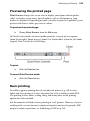
Previewing the printed page.................................................................... 245
Basic printing................................................................................................. 245
Printing special formats ............................................................................. 247
Publishing as PDF......................................................................................... 249
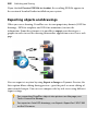
Exporting objects and drawings ............................................................. 250
Sharing via website ..................................................................................... 255
13. Index............................................................. 259
Contents
Welcome
1
2
Welcome
Welcome
3
Welcome to DrawPlus X3—the design and illustration solution from Serif,
fully certified for Windows Vista, and packed with all the features expected of
award-winning design software. From decorative page elements and logos to
full-page illustrations, scale drawings, multi-page publications, and Stopframe or
Keyframe animations— DrawPlus X3 does it all. With the power of scalable
vector graphics at your command, you'll see the creative possibilities open up
right before your eyes! Whether you're a beginner or an expert, you'll find easyto-use tools you can use right away. With this version, DrawPlus has broken the
price-performance barrier once again!
If you've upgraded from a previous version, this new edition of DrawPlus
includes a host of exciting new features (see p. 12) which complement the key
features listed overleaf.
Don’t forget to register your new copy, using the Registration Wizard on the
Help menu. That way, we can keep you informed of new developments and
future upgrades!
4
Welcome
Key features
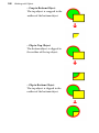
Document
•
Multipage Document Support
From startup to printout, the versatile DrawPlus engine sustains your
creativity. Choose from a wide range of preset document types,
including booklets and folded documents. Work on pages right side
up... automatic imposition assures correct order and orientation of
your output. Use DrawPlus's always-at-hand collection of popular
design templates to create designs quickly.
•
Import PDF
Unlock the contents of third-party PDF drawings using DrawPlus’s
impressive “open PDF” feature—objects can be brought into a new
drawing with a single-click for immediate editing.
•
Layers
Each page can have multiple layers so you can assign elements to
different layers for modular design. Each layer entry hosts a
hierarchical tree view of associated thumbnailed objects.
•
Rotate Canvas
Let your canvas rotate through any angle, just like an artist would do
in real-life. Great for artists with tablets, for drawing freeform curves
at any orientation, and for getting a different perspective of your
drawing!
•
Pseudo 3D Projections
Project objects isometrically onto Top, Front, or Right planes via a
Standard toolbar. For more advanced projections, take advantage of
editable Dimetric, Trimetric, Oblique projections, or even create your
own Custom projection.
•
View Quality
Draw in one of several drawing modes to view objects at optimum
quality (Normal mode), unsmoothed (Draft) or as single-pixel
outlines (Wireframe).
Welcome
•
5
Professional-Standard Drawing Features
Features like converting text to curves, defining custom envelopes,
fully customizable drop shadows, layers, and scalable vector graphics
give complete creative power. Combine two shapes into one... Subtract
for cropping and masking... Intersect to carve out unique shapes and
regions.
Design
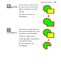
•
Cropping
Any object can serve as a "cookie cutter" for trimming one or more
other objects into a single shape... and the effect is reversible so you
won’t lose your originals. Great for creating “reflections” of complex
scenes!
•
Vector editing tools
Tools such as Knife Tool cuts through objects, leaving them in
multiple parts, still as vectors. The Erase Tool removes areas under a
brush line of variable nib width to redefine object boundaries! The
opposite of the Erase Tool, the Freeform Paint Tool "adds to" current
vector objects (shapes, text, bitmaps).
•
Comprehensive Design Gallery
The Gallery tab provides an impressive selection of instantly available
Arts & Crafts, Cartoons, ShapeArt, Connecting Symbols (family trees,
electronics, computers), and Layout Symbols (garden and interior
design), and many more. Use the Gallery to additionally store and
organize your own favourite designs for future use!
•
Picture Import and Adjustments
Import pictures from hard disk, CD/DVD, PhotoCD, digital camera or
scanner. Use image adjustments for quick fixes (or special effects)
including Red Eye Tool, Auto Levels, Auto Contrast,
Brightness/Contrast, and many more. Apply adjustments singularly or
in combination.
6
Welcome
•
Object Default control
Set your intended object’s default line colour/style, fill, and
transparency before even drawing your object! As a more powerful
default control, Synchronize Defaults lets you adopt a currently
selected object’s attributes for future objects; For example, select a red
brush stroke, to subsequently paint in red, then a green brush stroke to
paint in green; all or selected attributes can be affected. Global and
object-specific defaults can be reset independently.
•
Resource Management
Swap out your already placed bitmaps or text fragments in Drawing
mode or any Animation mode from the new Media tab; a Keyframe
animation’s movie or audio clip can also be replaced.
Colour and Transparency
•
Design Power with Colour Gradient Fills
The Gradient Fill Editor allows you to adjust gradient contour and tint
any portion of the colour spread, locate key colours precisely... and
select from RGB, HSL, CMYK, PANTONE® or Registration colours via
a Colour Selector.
•
Advanced Fill Support
Simply apply solid colours from the Studio’s Colour tab or Swatches
tab onto a fill path to add or replace colours for more subtle gradients.
Choose colours from different colour mixing modes in the Colour
tab—HSL Wheel, HSL Square, RGB Sliders, CMYK Sliders or
Tinting all offer different ways to mix colour. Load RGB, CMYK and
coordinated "themed" palettes from within the Swatches tab. Apply
high-end linear, radial, conical, ellipse, three colour, four colour,
square, and plasma fills to any text or shape for exciting, professional
results. Use bitmap fills for textures and backgrounds. Add, view, edit,
or delete colours used in your current drawing from within a saveable
Document Palette. Even import your own bitmaps and use them as
fills on DrawPlus objects! Plus Mesh Fills for impressively varied
gradients using a path-node network. Define new colour sets based on
a base colour—this linkage can transform the drawing's colour scheme
instantly, by simply modifying that base colour!
Welcome
•
7
Transparency Effects
Transparency can make the difference between flat, ordinary visuals
and sparkling realism! And DrawPlus provides it all—a full range of
transparencies for shading, shadows, reflections, depth effects, and
more.
Lines, brushes, and shapes
•
Versatile Line Drawing
Sketch using calligraphic lines with an adjustable pen angle. Add
rounded corners when and where you need them... and choose
different end caps and joins. Create decorative chain lines for
marching footprints, themed borders, and much more.
•
Dimension Lines and Scale Setting
Click a couple of times to take linear or angular measurements of any
object on the page—DrawPlus displays the dimension using your
choice of ruler units, at your specified scale (say, one inch to two feet).
Dimensions update when objects are moved or resized! Design room
layouts, make maps, draw scale models, and more.
•
Connectors
For drawing dynamic flow diagrams, schematics, family trees, and
organization charts, connector objects let you link your boxes and
symbols and then rearrange at will. Connection points stay put on
each object... keeping connections intact. Auto Connectors
intelligently display bridges at line crossings, and even route
themselves around obstructive objects.
•
Natural Curve Editing
Simply click and drag to break and redraw a curve at any node. Apply
smoothing selectively to freeform curves to eliminate that “shaky
hand” appearance.
•
Intelligent Curve Tracing
Simply “connect the dots” to trace around curved objects and
pictures... the Pen Tool features Smart segments that use automatic
curve-fitting to connect each node!
8
Welcome
•
Brushes
Unleash the painter within you, with DrawPlus's powerful Paintbrush
Tool and the supporting Brush tab's galleries! Pick from natural media
brush types such as acrylic, charcoal, dry paint, pastel, pen, and
watercolour, or create your own. Using a pressure-sensitive pen tablet?
Pressure sensitivity is supported (via a Pressure tab) with preset or
custom pressure profiles and control over the maximum and
minimum pressure applied.
•
QuickShapes
QuickShapes work like intelligent clipart… or the most powerful set of
drawing tools you’ve ever envisaged. Even extremely complex shapes
like spirals, stars, and webs are simple to draw and customize using
QuickShapes. Type text directly into any shape!
•
Working with Text
Apply and edit artistic, frame, or shape text right on the page... apply
basic formatting from the always-at-hand Text context toolbar.
Control advanced properties like text flow (wrap), kerning, leading,
paragraph indents, above/below spacing. Need foreign language
support? Simply paste text in Unicode format as either formatted RTF
or unformatted plain text. Font substitutions during the opening of
DrawPlus or PDF files offers an interactive means of managing
missing fonts. Use Spell Checker to proof your output—check any
text against an editable user dictionary.
Text
Effects
•
Perform Powerful Blends
The Blend Tool allows adjustment of blend steps, transform, and
attribute profiles (rate of change). Objects can be multiply-blended
(to/from other blends) to create truly stunning illustrations.
•
Instant 3D with on-screen transforms
Transform 3D objects with in-situ 3D rotational control and editing.
Apply awesome multi-coloured lighting effects (with directional
control), along with custom bevel and lathe effect profiles to create
your very own unique contours. Hardware-accelerated rendering
boosts redraw performance (hardware dependent).
Welcome
9
•
Perspective Effects
Get a new slant on things... With a context toolbar flyout full of presets
plus a built-in tool for freeform adjustments, the Perspective Tool lets
you tilt and skew text (or any other object) for truly “spatial” results!
•
Roughen Tool
For jagged, jaunty edges on text, lines, or QuickShapes, just drag the
tool up or down for subtle or bold results.
•
Border Wizard
Vastly flexible Border Wizard instantly adds borders to the page or to
individual objects. Choose a border from the extensive library, or be
creative and let Border Wizard guide you through building a unique
design.
•
Filter Effects
Drop shadows starting to wear a bit thin? Enliven your text with fully
adjustable Inner Shadow, Glow, Bevel, and Emboss filters... easy to
apply and sure to impress. Apply soft edges with the Feathering filter
effect—great for blends, montages, vignetted photo borders, and much
more.
•
Astounding 3D Lighting and Surface Effects
Advanced algorithms bring flat shapes to life! Choose one or more
effects, then vary surface and source light properties. Adjust
parameters for incredible surface contours, textures, fills. The Studio's
Effects Tab offers preset 3D effects you can apply and customize as
you wish.
Web and Animation
•
Web Image Slices, Image Maps, Rollover States
Beat the pros at their own game by using these techniques to add links
to your Web graphics! With a few clicks, divide images into
segments—each with its own hyperlink and popup text—or add
hotspots to specific regions. Even let DrawPlus create interactive
rollover Web graphics that highlight or change state when users
mouse over or click!
10 Welcome
•
Stopframe Animation
Tap the power of QuickShapes to turn out Web stopframe animations
in no time—using advanced features like onion skinning,
backgrounds, overlays, and frame management.
•
Keyframe Animation
Produce smooth, professional and quick-to-design animations as
Adobe® Flash® files, all from within the Storyboard tab. The Easing
tab defines editable envelope profiles for defining the rate of change of
an object's transformation and attributes. The Actions tab can assign
"events" (mouse click, hover over, and many more) and an associated
action (e.g., jump to a named URL or animation marker); develop
directly in ActionScript for the more adventurous! Use the Keyframe
Camera to pan, zoom, or rotate around your animation's keyframes.
Add sound and movies to any Keyframe animation. Export to Flash,
Flash Lite/i-Mode, screensaver or a choice of video formats.
Export and Print
•
Image Export Optimizer
The Export Optimizer lets you see how your image will look (and
how much space it will take up) before you save it! Its multi-window
display provides side-by-side WYSIWYG previews of image quality at
various output settings, so you can make the best choice every time.
Use Dynamic Preview to work in an edit-and-preview mode at a
given DPI, file format, and number of colours.
•
PDF Export
Step up to the worldwide standard for cross-platform, WYSIWYG
electronic information delivery. Your PDF output will look just like
your DrawPlus document... in one compact package with embeddable
fonts, easily printable or viewable in a Web browser.
Welcome
•
11
Professional Print Output
PDF publishing to the PDF/X-1 or PDF/X-1a file format is a great
choice for professional output from DrawPlus. Deliver with
confidence to your print partner, safe in the knowledge that your
single composite print-ready PDF drawing includes all fonts and
colour information for spot or process colour separation. Select file
information, crop marks, registration targets, and densitometer/colour
calibration bars for inclusion in your PDF. Spot or process colour
(CMYK) separations for full colour printing are possible. You have full
control over prepress settings for output.
12 Welcome
New features in DrawPlus X3
Images
•
AutoTrace (p. 179)
Convert bitmaps to vector art with AutoTrace studio. Adopt preset
profiles for optimum tracing of bitmapped logos, as well as colour
and black and white photos. Create your own custom profiles for
tracing files with similar characteristics. Use adjustment tools for
fine-tuning traced output (add/remove colours, merge areas, smooth
curves, or erase nodes).
•
Quick-and-easy image cutouts (p. 173)
Image Cutout Studio makes light work of cutting out your placed
images, directly within DrawPlus. Use brushes to discard uniform
backgrounds (sky, walls, etc.) or keep subjects of interest (people,
objects, etc.). Two output types—Alpha-edged Bitmap or Vectorcropped Bitmap—offer transparency blending or feathering
techniques at the cutout edge to seamlessly merge your image with
your page.
Ease of Use
•
Opacity control in Colour tab (p. 162)
For improved productivity, any colour chosen in DrawPlus can now
have an associated Opacity applied at the same time. Great for setting
colour/opacity combinations on objects or nodes on fill paths!
•
Improved toolbars
The Standard toolbar now sports large icons for better visual cues, and
hosts the now always-at-hand 3D Planes and Overlays options for
perspective drawing and design aids.
•
Lasso selection (p. 55)
Difficulty selecting complex objects? For better control, use the Alt key
with your Pointer Tool and draw a lasso around objects. Even lasso
nodes while editing curves.
Welcome
13
Design
•
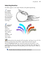
Spray brush strokes (p. 81)
Have some painting fun with spray brushes from categories such as
Airbrushes, Grunge, and Special Effects; change brush colours to suit
your design or adjust brush nozzle control.
•
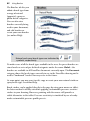
Brush and edge effects on object outlines (p. 147)
Bored of solid line fills? Try stroking a brush outline around artistic
text, image, and shapes. Alternatively, use textured edge brushes for
ripped, painted, smudged, glowing or burnt edges.
•
Design aids (p. 42)
Use Overlays such as Rule of Thirds grid (for improved page
composition) and Divine Proportions (for aesthetic proportioning).
For more focused design, use Solo mode to work on an object in
isolation.
•
New stunning 2D and 3D filter effects (p. 193 and p. 196)
Blur any object or create a coloured solid or gradient outline around
object edges (use the new Contour fill which applies gradient fill from
the inner to outer outline width). 3D effects are boosted with
Reflection Maps which offer a realistic glass-like transparency control
of non-reflective/reflective surfaces. Multiple separately coloured
lights are added for dramatic lighting effects. All filter effects can now
be applied in preview mode or to the object on the page.
•
Powerful object cropping (p. 110)
The Crop Tool makes cropping your design or imported image more
instinctive and intuitive. An on-document control bar lets you
transform the crop window, with respect to position, rotation, and
shape. Crop to preset Crop Shapes. For better composition while
cropping, use a cropping Rule Thirds grid.
Importing and Exporting
•
Open picture as document (p. 24)
Pictures can now be opened in DrawPlus as a new document
automatically sized to the picture dimensions. Add design objects
(captions, line, or shapes) and then export.
14 Welcome
•
Export selected regions (p. 252)
Easily draw and size an overlay region around an area of your design,
then export it via Export Optimizer!
•
HD Photo and PostScript files (p. 171)
Import and export as Microsoft's new HD Photo file format! Import
Encapsulated PostScript files (.eps) as well.
•
Open Adobe Illustrator files (p. 25)
Open and edit Adobe Illustrator files (9.0 and above) directly into
DrawPlus.
•
A new metafile format (p. 171)
Import and export Serif Metafiles (.SMF), a proprietary image format
with improvements to the Windows Metafile format (WMF). Better
line, fill, and text definitions make them ideal for sharing graphics
between Serif applications.
Sharing
•
Share your designs online! (p. 255)
Upload your DrawPlus design to the community website,
www.drawplus.com. View designs using powerful zoom technology,
give a star rating, comment on, or search for any design by tag. Create
public or private groups for like-minded designers—great for making
new friends! Take part in design forum discussions.
..and some other enhancements you've requested
•
The new Arrange tab consolidates all your tools for object ordering,
flipping, cropping, combining, and joining. Export Optimizer now
shows all export settings. Create and scale objects from their centres.
The Knife Tool has been "sharpened up" with different cutting types
(square, zig-zag, wave, and more) and preset cookie cutter shapes
(ellipses, rectangles, stars, and more). Easily apply Material Thickness
and a Feather Edge directly via the Effects tab. Brushes now include
photo-based stitches, laces, zippers, and spray effects. Now manipulate
transparent bitmap outlines instead of the bitmap’s bounding box.
Welcome
15
Installation
System Requirements
Minimum:
•
Windows-based PC with DVD/CD drive and mouse
•
Microsoft Windows® XP or Vista operating system
•
512MB RAM
•
438MB (recommended full install) free hard disk space
•
1024x768 monitor resolution
Additional disk resources and memory are required when editing large or
complex documents.
To enjoy the full benefit of brushes and their textures, you must be
using a computer whose processor supports SSE (most modern
computers do). On brush selection, an on-screen message will
indicate if your computer is non-SSE.
Recommended:
As above but:
•
Multi-processor PC technology
Optional:
•
Windows-compatible printer
•
TWAIN-compatible scanner and/or digital camera
•
Pressure-sensitive pen tablet (Serif GraphicsPad or equivalent)
•
3D accelerated graphics card with DirectX 9 (or above) or OpenGL
support
•
Internet account and connection required for accessing online
resources
16 Welcome
First-time install
To install DrawPlus X3 simply insert the DrawPlus X3 Program CD into your
DVD/CD drive. The AutoRun feature automatically starts the Setup process. (If
it doesn’t, follow the manual install procedure described below.) Just answer the
on-screen questions to install the program.
Manual install/re-install
To re-install the software or to change the installation at a later date, select
Settings/Control Panel from the Windows Start menu and then click on the
Add/Remove Programs icon. Make sure the DrawPlus X3 Program CD is
inserted into your CD/DVD drive, click the Install… button and then simply
follow the on-screen instructions.
Getting Started
2
18
Getting Started
Getting Started
19
Startup Wizard
Once DrawPlus has been installed, you're ready to start. Setup adds a Serif
DrawPlus X3 item to the All Programs submenu of the Windows Start menu.
•
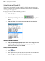
Use the Windows Start button to start DrawPlus (or if DrawPlus is
already running, choose New>New from Startup Wizard... from the
File menu) to display the Startup Wizard.
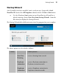
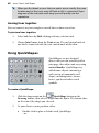
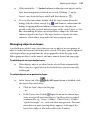
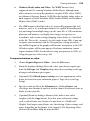
The Startup Wizard offers different routes into the program for you to explore:
The above options are described as follows:
Create
Allows you to....
Start New
Drawing
create a drawing from scratch
Keyframe
Animation
create a Keyframe animation in
Keyframe animation mode
Stopframe
Animation
create a Stopframe animation in
Stopframe animation mode
20
Getting Started
Open
Open
Saved
Work
open and edit your saved DrawPlus
drawings
Design
Template
create an instant drawing or animation
from a design
Import
PDF
create a design from an existing PDF
file.
Sample
Designs
load some example drawing files to
boost your imagination!
Browse
Tutorials
access the DrawPlus tutorials
Online
Videos
View a selection of online product
videos
View
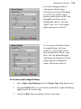
Use the Choose Workspace drop-down menu to choose your workspace
appearance (i.e., Studio tab positions, tab sizes, and show/hide tab status). You
can adopt the default workspace profile <Default Profile>, the last used profile
<Current Profile>, a range of profile presets, or a workspace profile you've
previously saved.
The Startup Wizard is displayed by default when you launch DrawPlus. If you
don’t want to use the Startup Wizard again, check the “Don't show this wizard
again” box. You can switch it on again via Startup Wizard in Tools>Options...
(use Ease of Use menu option).
You can also access the Startup Wizard at any time from New>New from
Startup Wizard... on the File menu.
Getting Started
21
Starting with a design template
It's so much easier creating drawings with a little bit of help—DrawPlus can
utilize a whole range of design templates which will speed you through the
creation of all types of drawings and animations! Templates can be thought of as
“object factories.” They let you pick a design and leave you with one or more
new objects on the page.
If the design is exactly what you want then all that is left is for you to print it or
export it. If you want to personalize the design or add to it then you need to
know how to work with objects (see p. 105)!
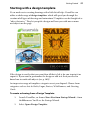
An impressive range of templates categories are at you disposal. Choose from
categories such as Arts & Crafts, Logos, Posters, Web Banners, and Greeting
Cards.
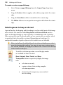
To create a drawing from a Design Template:
1.
Launch DrawPlus, or choose New>New from Startup Wizard... from
the File menu. You'll see the Startup Wizard.
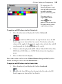
2.
Select Open>Design Template.
22
Getting Started
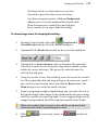
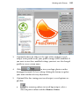
3.
From the dialog, select a drawing category on the left, and examine the
designs on the right. Click the thumbnail that's closest to the one you
want, then click Open.
The design is loaded and forms the basis of your new unsaved drawing or
animation. When you make any changes, you'll be prompted to save the drawing
or animation to a file name.
You can save any drawing or animation as a template (see Saving
templates; p. 27) at any time.
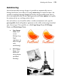
Starting with a new drawing
The first time you launch DrawPlus, you'll see the Startup Wizard, with a menu
of choices. The Start New Drawing option offers an easy way to create your new
drawing and takes care of the initial setup for the particular type of document
you'll be producing.
Choose from a wide range of preset document types, including booklets and
folded documents. Work on pages right side up... automatic imposition assures
correct order and orientation of your output.
To start a new drawing from scratch using the Startup Wizard:
1.
Start DrawPlus (or choose File>New>New from Startup Wizard... if
it’s already running).
2.
Select Start New Drawing from the Startup Wizard.
3.
Select a document category from the Documents pane (and a subcategory if applicable). Categories contain preset document types or if
you select Regular, you can choose from standard document sizes
presented in Portrait or Landscape sub-categories. For custom sized
pages, choose the Custom Page Setup button at the bottom of the
dialog.
4.
Select a document type thumbnail from the right-hand pane and click
Open. The new document opens.
The My Templates category lets you base your new drawing on a
previously saved template.
Getting Started
23
To start a new drawing during your DrawPlus session:
•
Click
New Drawing on the Standard toolbar (if Startup Wizard
is disabled).
- or Choose New>New Drawing from the File menu.
You'll get a new drawing in a new untitled window each time you choose this
method—the default page size is adopted.
You can always adjust the page size and document format later via
File>Page Setup....
To turn on/off the Startup Wizard:
1.
Choose Options... from the Tools menu.
2.
Click Ease of Use and check/uncheck Startup Wizard.
To start with a new animation, see Getting started with animation
on p. 207.
Use Import PDF from the Startup Wizard to unlock the contents of
third-party PDF drawings.
Opening a saved document
You can open an existing DrawPlus drawing from the Startup Wizard, Standard
toolbar or the File menu. Once open, drawings can be made currently active
from a drawing tab or via the Window menu.
To open an existing document from the Startup Wizard:
1.
Select Open Saved Work option. In the Documents pane of the Open
Saved Work dialog, you'll see either your computer's folder structure
for navigation to your DrawPlus drawings (Folders tab) or a list of
most recently used drawings (History tab). Preview thumbnails are
shown in the adjacent pane.
2.
Select a thumbnail from the pane, then click Open.
24
Getting Started
To open an existing document via toolbar or menu:
Open on the Standard toolbar, or select File>Open....
1.
Click
2.
In the Open dialog, navigate to, then select the file name and click the
Open button.
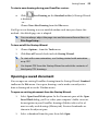
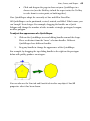
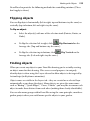
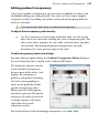
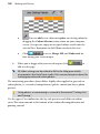
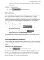
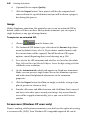
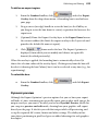
Displaying drawings
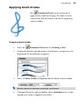
If you open multiple
drawings at the same time,
you can easily jump between
drawings by selecting a
drawing name from the
Window menu. Unsaved
drawings are indicated by an
asterisk; the currently active
document is shown with a
tick.
Alternatively, you can simply
click on a open drawing's tab
at the top of the workspace
to make it active (e.g., the
unsaved drawing "Peppers").
Drawings that are not active
are greyed out.
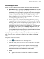
Opening other file types
Opening images as a new document
DrawPlus allows a comprehensive range of image file formats to be opened, each
as a separate DrawPlus document. From the document, you can add your own
text captions, lines, shapes, or simply make image adjustments. You can save
your design changes as a new project or just export the image (with or without
adjustment), while preserving its original properties.
Getting Started
25
To open an image:
Open on the Standard toolbar.
1.
Click
2.
Change the file type drop-down menu to display All Image Files,
locate and select the file, and click Open. The image occupies your
workspace such that page dimensions are adjusted to match the image
dimensions (a Custom page size is adopted; in pixels).
3.
(Optional) You can modify the image—modify the document as for
any other document or double-click the image to load the Image
Adjustment dialog (then apply one or more adjustments).
4.
Save to save the document as a DrawPlus .dpp project, or
Click
File>Export>Export as Image... to export it to the same or a different
file format (the original image's name, dpi, colour depth, and
transparency settings are maintained for export).
Opening PDF and Adobe Illustrator files
It is possible to open PDF and Adobe Illustrator files—once opened you can save
the either file format as a DrawPlus Drawing (.DPP). The character formatting,
layout and images in the original document are preserved to allow for editing of
the imported content.
To open a PDF or Adobe Illustrator file:
1.
Click
Open on the Standard toolbar.
For PDF files, you can also select Import PDF from the Startup
Wizard.
2.
From the dialog, navigate to, then select the file, and click Open. The
document is loaded and the drawing will repaginate to the number of
pages of the original document if multi-page (PDF only).
26
Getting Started
Opening AutoCAD files
DrawPlus opens AutoCAD® .dwg and .dxf files quickly and easily. Using the
same process as that for PDF files, this creates an opportunity to not only view
engineering layouts and designs (up to AutoCAD 2006) in DrawPlus, but to edit
the drawn objects and to save the drawing as a DrawPlus Drawing (.DPP).
On file open, a DXF/DWG Options dialog provides options to scale the
imported file objects, position the artwork on the page and merge objects onto
one layer.
To open an AutoCAD file:
Open on the Standard toolbar.
1.
Click
2.
Change the file type drop-down menu to display AutoCAD files
(*.dwg,*.dxf), locate and select the file, and click Open.
3.
In the dialog, specify scaling and positioning options. Uncheck Merge
Layers to retain the layer structure of the original AutoCAD file—
layers will automatically be shown in the Layers tab.
4.
Click OK. The AutoCAD drawing is imported.
Getting Started
27
Saving your work
DrawPlus saves its documents as .dpp (Drawing), .dpx (Template) or .dpa
(Animation) files (for Stopframe and Keyframe animation modes).
To save your work:
•
Click
Save on the Standard toolbar.
- or To save the document under its current name, choose Save... from the
File menu.
- or To save under a different name, choose Save As... from the File menu.
Saving templates
If you've decided that a particular design might be useful in future you can save
the layout as a template. You can save any DrawPlus drawing as a template
(*.dpx) file. When opening a saved template file, DrawPlus automatically opens
an untitled copy, leaving the original template intact.
To save a drawing as a template:
1.
Choose Save As... from the File menu. Under "Save as type:" select the
DrawPlus Template (*.dpx) option. By default, the template will be
saved to a "My Templates" folder so that your templates will be
accessible for future use (see Starting with a new drawing on p. 22).
2.
Enter a file name, leaving the file extension intact, and click Save.
To edit a template file directly:
1.
Choose Open... from the File menu and select DrawPlus Templates
(*.dpx) in the "Files of type:" box.
2.
Navigate to the folder containing your saved template file and select it.
3.
To open the original template, uncheck the Open as untitled option.
4.
Click the Open button. You can then make edits to your template.
28
Getting Started
Closing DrawPlus
To close the current document:
•
Choose Close from the File menu or click the window's
button.
- or -
Close
If you have a middle mouse button (wheel), click it when you hover
over the document tab at the top of your workspace.
If the document is still unsaved or there are unsaved changes, you'll be prompted
to save changes.
To close DrawPlus:
•
Choose Exit from the File menu.
For each open window, you'll be prompted to save any changes made since the
last save.
Working with
Pages
3
30 Working with Pages
Working with Pages
31
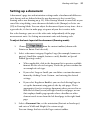
Setting up a document
A document's page size and orientation settings make a fundamental difference
to its layout, and are defined when the new document is first created (see
Starting with a new drawing on p. 22). If the Startup Wizard is turned off, or you
cancel the setup dialog, a new document defaults to A4 (Europe) or Letter size
(US) in Drawing Mode. You can adjust the document layout at any time—but as
a general rule, it's best to make page setup one of your first creative tasks.
For scale drawings, you can set the ruler units independently of the page
measurement units. See Setting measurement units and drawing scale.
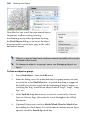
To adjust the basic layout of the document (Drawing mode):
1.
from the context toolbar (shown with
Choose
Pointer or Rotate Tool selected).
2.
Select a document category: Regular, Large (for example, banners or
posters), Small (for example, business cards), Booklet, or Special
Folded (greetings cards).
3.
•
Where applicable, click in the document list to preview available
formats for the selected category. Watch the preview window for
an example of each type.
•
If you select Large or Small, you can define a custom document
format by clicking Create Custom... and entering the desired
settings.
•
If you select Regular or Booklet, you can check Facing Pages to
set up the document using paired, side-by-side pages. This is
appropriate if you're creating a document where you need to see
both the left-hand (verso) and right-hand (recto) pages, or one
that employs double-page spreads where a headline or other
element needs to run from the left-hand page to the right-hand
page.
Select a Document Size, set the orientation (Portrait or Landscape)
and enter a Width and Height (if a custom setup).
You can change this later via the Pages context toolbar.
32 Working with Pages
4.
Adjust the document Margins to your specifications. You can set the
left, right, top, and bottom margins individually, or click the From
Printer button to derive the page margin settings from the current
printer settings. The dialog also provides options for Balanced
margins (left matching right, top matching bottom) or for two
Mirrored margins on facing pages where the "left" margin setting
becomes the "inside," and the "right" margin becomes the "outside."
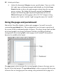
Using the page and pasteboard
Most of the DrawPlus display is taken up by a page or "artwork" area and a
surrounding pasteboard area. This arrangement is an electronic equivalent of
the system used by traditional graphic designers. They kept design tools and bits
of text and graphics on a large pasteboard, and then carefully pasted final
arrangements of text and graphics onto a page-sized "artwork" sheet pinned
down in the middle of the board.
The page area is where you put the text and graphic elements that you want to
be part of the final output. The pasteboard area is where you generally keep any
elements that are being prepared or waiting to be positioned on the page area.
Working with Pages
33
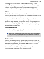
Setting measurement units and drawing scale
For precision drawing, you need techniques that allow you to position and draw
accurately without effort, which will also be of use at any scaled size. Such
techniques make use of rulers and guides for actual-size or scaled drawings.
Rulers
The DrawPlus rulers mimic the paste-up artist's T-square, and acts as a
measuring tool and guide creator. The rulers that surround the page allow you to
measure the exact position of an object.
Ruler units used by DrawPlus determine the units displayed on the rulers and
the reported units shown when positioning and scaling objects (either around
the object or on the Hintline). You can change the ruler units without altering
the document's dimensions. Unit settings are saved with your DrawPlus
document; as a result loading different documents, templates, etc. may change
your working measurement units.
To change the page unit:
•
Choose Options... from the Tools menu and click Layout, then make
a selection in the Ruler Units box.
Ruler Units are equivalent to Page Units unless you're working on a
scale drawing. For example, at 100% zoom, one ruler centimetre
equals one centimetre on the printed page
Moving rulers
By default, the horizontal ruler lies along the top of the DrawPlus window and
the vertical ruler along the left edge. The default ruler intersection is the top-left
corner of the pasteboard area. The default zero point (marked as 0 on each
ruler) is the top-left corner of the page area.
To move either ruler to a different position, click and drag on the ruler
intersection button (showing the type of measurement unit).
34 Working with Pages
The small tab that is shown on the intersection button can be used to set a
new ruler origin—simply drag the tab onto the page and release to set the
position of your new origin (cross-hair guides and the Hintline toolbar help this
positioning). Double-click on the intersection to reset the origin back to its
default position. All guide positions are recalculated as the origin changes
position.
Double-click on the ruler intersection to make the rulers' zero point jump to the
top left-hand corner of the selected object.
This comes in handy for measuring page objects. If the rulers have already been
moved or the object is deselected, double-clicking on the intersection will send
the rulers back to the default position.
Working with Pages
35
Rulers as a measuring tool
The most obvious role for rulers is as a measuring tool. As you move the mouse
pointer, a small line marker along each ruler displays the current horizontal and
vertical cursor position. When you select an object the rulers not only show its
position, but also its extent by a lighter coloured area (also showing the object's
dimensions).
Creating guides
If you want to position objects repeatedly on the same horizontal or vertical
boundary then guides can be used. DrawPlus lets you set up horizontal and
vertical guides—non-printing, red lines you can use to align one object with
another. Guides are “sticky” as long as you have Snap to Guides turned on (via
Tools>Options>Snapping), i.e. a moved object will behave as if it is attracted to
a guide as you move it close to the line. Guides also attract the object when you
are changing its size.
36 Working with Pages
To create a guide:
•
For a horizontal or vertical guide, click on the horizontal or vertical
ruler, respectively, and drag onto the page while fine-tuning the guide
into its position.
Hold down the Alt key before guide creation to produce a
horizontal guide from a vertical ruler and vice versa.
To move, delete and lock guides:
•
To move a guide, click and drag it into position with the Pointer Tool.
•
To remove a guide, drag and drop it onto the respective ruler.
•
To lock the guides and prevent them from being moved, choose
Options... from the Tools menu, click Snapping, and check the Lock
Guides box (or right-click on a ruler).
•
To show or hide guides, check or uncheck Layout Tools>Guides from
the View menu.
Drawing scale
You can create scale drawings (such as a house plan or model diagram) by
setting a ratio other than 1:1 between page units and ruler units. For example,
you might wish to set one page inch equivalent to ten (ruler) feet.
Right-click anywhere on your rulers to quickly swap to a different
unit of measurement—the rulers and Transform tab are updated
instantly.
Working with Pages
37
To change the drawing scale:
1.
Choose
from the context toolbar (shown with
Pointer or Rotate Tool selected).
2.
Check the Scale Drawing box.
3.
Use the input boxes to set the drawing scale as a proportion between
the Page Distance (in page units that define the document's actual
printing dimensions) and the Ruler Distance (in on-screen ruler units
that represent the "real world" objects you're depicting). Units and
object dimensions update and scale accordingly.
Using snapping
With Snapping enabled, objects you create, move, or resize will jump to align
with nearby, visible guides or a defined grid, respectively. For snapping to
guides, think of an object as being broken into four quadrants such that you drag
from the object's upper right quadrant (below) towards the guides to produce
the "snapping" effect.
38 Working with Pages
To turn snapping on and off:
1.
Choose
from the context toolbar (shown with Pointer
or Rotate Tool selected).
2.
In the Snapping pane, check or uncheck the Snapping box.
Alternatively, switch Snapping on or off via the Arrange menu.
To snap to guides and/or grid:
•
With the Snapping option checked, check the Snap to Guides and/or
Snap to Grid option in Tools>Options>Snapping.
If you find snapping bothersome, it may be that you have the grid spacing set too
coarsely to allow you the freedom you need in your design. Go to
Tools>Options>Snapping to set a finer horizontal and/or vertical grid spacing
(you can also change grid colour and style).
To show or hide the snapping grid:
•
Choose Layout Tools from the View menu and check or uncheck
Snapping Grid on the submenu.
- or Choose Options... from the Tools menu and click Snapping, then
check or uncheck the Display Grid box.
Working with Pages
39
Viewing pages
The HintLine toolbar at the bottom of the screen displays the current page
number and provides a number of controls to let you navigate around your
pages. As an alternative, the Pages tab shows your pages as thumbnails, which
when selected, will display that page in your workspace.
Once you've got a page in view, you can use the scrollbars at the right and
bottom of the main window to move the page and pasteboard with respect to the
main window. As you drag objects to the edge of the screen the scroll bars adjust
automatically as the object is kept in view.
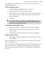
To go to a specific page:
1.
from the context toolbar (shown with
Choose
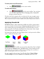
Pointer or Rotate Tool selected).
2.
On the Page Manager's Go to Page tab, type the page number to go to
and click OK.
- or -
1.
Display the Pages tab (docked at the bottom of your DrawPlus
workspace) by clicking the
button.
2.
Click on a thumbnail to jump directly to that page.
To navigate pages:
•
Click
Previous Page,
Next Page,
Page on the HintLine toolbar.
First Page or
Last
40 Working with Pages
Zooming
The Hintline toolbar also allows the user to view and/or edit the page at
different levels of detail. You can zoom in/out step-by-step or by a userdefined/preset amount. Panning is also possible.
The Current Zoom setting on the toolbar displays the current zoom
percentage, with 100% representing an actual-size page. Click over the value,
then type to enter any zoom percentage up to 5000% or select a preset zoom
from the flyout list (includes fit to Full Page or Page Width).
To zoom to a particular view:
•
Click
Zoom Out or
Zoom In to decrease/increase the current
zoom percentage with each click.
•
Click
Zoom Tool and drag out a rectangular marquee on the
page to define a region to zoom in to. The zoom percentage adjusts
accordingly, fitting the designated region into the window. To zoom
out, hold down the Shift key when dragging or just right-click on the
page. You can also pan around a zoomed-in page while the Ctrl key is
pressed. To zoom to the current selection, choose Selection from the
View menu.
•
Click
Pan Tool to use a hand cursor to click anywhere on the
page and drag to reposition the page in the window.
•
Click
Fit Page to adjust the zoom percentage so the entire page
area is displayed in the window.
If you're using a wheel mouse, you can scroll the wheel forward or back to move
up or down the page, or move horizontally left or right by using the Shift key
and scrolling together. Try combining the Ctrl key and scrolling up or down for
immediate in/out zoom control.
Working with Pages
41
Adding and deleting pages
DrawPlus uses the Page Manager to add one or more pages before or after a
currently selected page; you can even make use of an object "cloning" feature
which copies objects from a chosen page.
To add one or more new pages:
1.
Select a page from which to add page(s) before/after.
2.
from the context toolbar (shown with
Choose
Pointer or Rotate Tool selected)..
3.
On the Page Manager's Insert Page tab, specify the following:
4.
•
The number of pages to add
•
The page before (or after) the new pages should be added
•
Whether to duplicate a particular page by copying objects from it
Click OK.
The document format (as determined in File>Page Setup...) will
determine whether or not you can add or delete pages. For
example, Folded documents have a fixed number of pages.
To delete one or more pages:
1.
Choose
from the context toolbar (shown with
Pointer or Rotate Tool selected)..
2.
On Page Manager's Delete Page tab, specify the following:
• The number of pages to delete
• The page after which pages should be deleted
3.
Click OK.
To duplicate a page:
•
On the Insert Page tab, you can specify how many pages to add, and
where to add them. Check Copy objects from page if you want to
duplicate a particular page.
42 Working with Pages
To make a page a background for other pages:
•
From the Pages tab, right-click the intended background page and
choose Set as Background (to undo choose Unset as background).
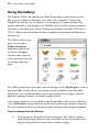
Using design aids
DrawPlus provides a number of tools to assist you as you design. Each is
designed to improve stroking lines/brushes, page composition, and focused
design on specific areas on the page.
•
Rotating your canvas
•
Applying the Rule of Thirds
•
Using divine proportions
•
Isolating an object
Typically the tools can be switched on or off.
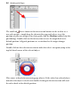
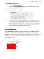
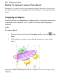
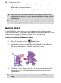
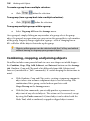
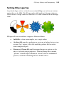
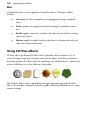
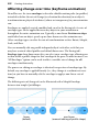
Rotating your canvas
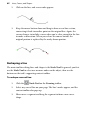
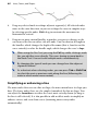
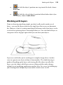
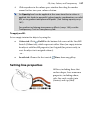
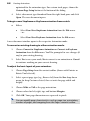
Rotating your canvas helps you to maintain natural flow when drawing freeform
lines, curves, or brush strokes, where the artist uses the wrist as a pivot
(especially when using a pen tablet). If you rotate the canvas by a chosen angle
then the drawing becomes easier—taking advantage of the natural arc of the
drawing hand.
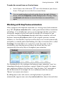
Working with Pages
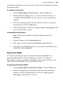
43
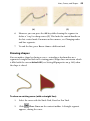
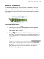
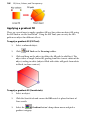
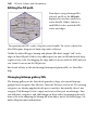
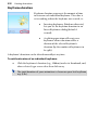
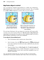
The above example illustrates how grass-like brush strokes can be added more
easily to a canvas once it has been rotated 30°!
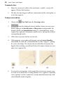
To rotate your canvas:
Either:
1.
Rotate Canvas on the Hintline toolbar (don't click the
Click
down arrow).
2.
Hover over your workspace until you see the
cursor, then click
and drag to rotate the canvas clockwise or anti-clockwise.
3.
Once you're happy with the degree of rotation, release the mouse
button to reposition the canvas.
- or -
•
Click the down arrow on the
Rotate Canvas button (Hintline
toolbar) and choose a preset angle from the drop-down list.
You can also select an object and then choose To Object from the
Rotate Canvas drop-down list. The canvas adjusts so that the
object is positioned square to the X and Y axes.
To reset your canvas:
•
With the button enabled, double-click anywhere on the canvas to
reset.
44 Working with Pages
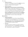
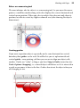
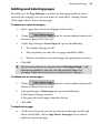
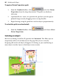
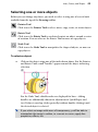
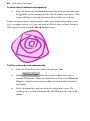
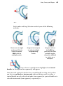
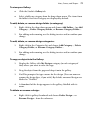
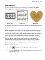
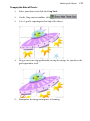
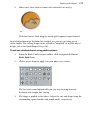
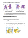
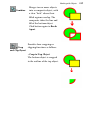
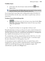
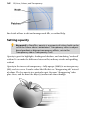
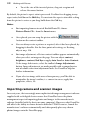
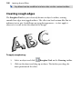
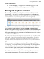
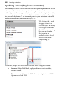
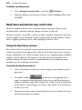
Applying the Rule of Thirds
Traditionally a technique used in
photography, the Rule of Thirds grid can
also be applied to your design to help with
its composition.
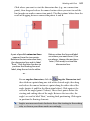
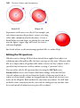
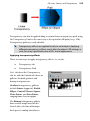
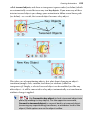
For example, note the way the primary
object (pear) is vertically aligned between
the top- and bottom-left intersecting
points, i.e. under the stalk and core. The
secondary object (orange) is located under
the opposite intersecting line to offer some
balance to the design.
By aligning objects to intersecting horizontal and vertical lines (rather than just
centring objects on the page) you can create designs with greater visual interest.
When a grid is applied to your page the displayed context toolbar lets you alter
the grid's colour and opacity, and reset or delete the grid. (See online Help.)
The grid is actually an overlay which appears as an ‘Overlay Layer’ in
the Layers tab. As such you can use the Visible layer control to
temporarily show/hide the grid.
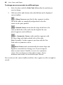
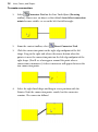
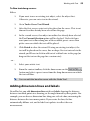
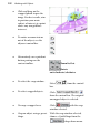
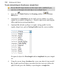
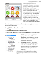
To apply a Rule of Thirds grid:
1.
From the Standard toolbar, click
and select Rule of
Thirds from the drop-down menu. A coloured grid is overlaid over
your page.
2.
(Optional) For selected objects, drag a corner (or edge) handle to
resize the grid; reposition the grid by dragging; rotate by dragging a
corner handle. The grid can be manipulated just like an object.
3.
Place pictures, frames, or vector objects under any of the intersecting
blue lines.
Working with Pages
45
Once applied, the grid stays selected. Clicking away from the grid will deselect it,
but it can be reselected at any time (e.g., for repositioning later).
To select the grid:
•
From the Standard toolbar, click
Rule of Thirds.
and choose Select
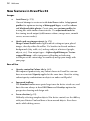
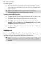
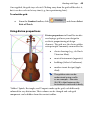
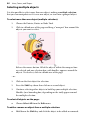
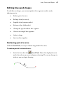
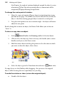
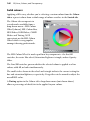
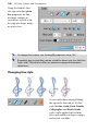
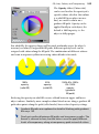
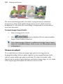
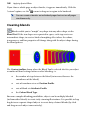
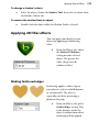
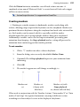
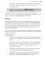
Using divine proportions
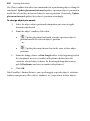
Divine proportions in DrawPlus involve
overlaying a grid over your design for
aesthetic proportioning of design
elements. The grid uses the classic golden
ratio principle commonly encountered in:
•
classic drawings (e.g., da Vinci's
Vitruvian Man).
•
musical instruments (opposite).
•
buildings (Athen's Parthenon).
•
modern iconic design (Apple
iPod).
The golden ratio can be
understood using a cello
as an example—the ratio
(0.618) is that between the
instrument's neck and its body.
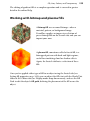
"Golden" Spirals, Rectangles, and Tangents make up the grid, each differently
coloured for easy distinction. Their colours can be changed and each grid
component can be hidden from the context toolbar.
46 Working with Pages
To apply a Divine Proportions grid:
1.
and select Divine
From the Standard toolbar, click
Proportions from the drop-down menu. The grid is overlaid over
your page.
2.
(Optional) Resize, rotate, or reposition the grid over your design (or
planned design area) by dragging corner or edge handles.
3.
Begin drawing, using the guide lines to draw objects proportionately.
To select the grid (once deselected):
•
From the Standard toolbar, click
Divine Proportions.
and choose Select
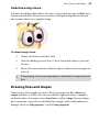
Isolating an object
For focused editing, DrawPlus X3 provides the Solo mode. This allows you to
temporarily isolate selected object(s) on the page that you are currently
designing (all unselected objects disappear!). In doing so, you avoid having to
move objects to other layers or lock object unnecessarily.
Working with Pages
•
47
Select the object, then click
Solo Mode on the Hintline toolbar.
After editing, click the button again to return to normal editing mode.
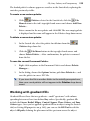
Updating defaults
When you create new objects in DrawPlus, the way they look depends on the
current default settings for that particular type of object. DrawPlus stores
defaults separately for (1) lines/shapes (including QuickShapes), (2) artistic text
objects, (3) connectors, (4) dimension objects and (5) brushes.
Defaults for shape text (as contained in shapes) are distinct from those for
artistic text, and are defined along with other shape defaults (they are subsumed
under other shape properties). For any object, default means the properties of
the object (line/fill attributes) that will be applied to the next new object (of the
same type) you create.
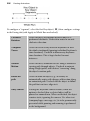
You can adopt two approaches to controlling your defaults according to your
preferred way of working, i.e.
On
Synchronize
Defaults (from flyout
on Standard toolbar)
Defaults are changed dynamically by
synchronizing to the colour, style,
transparency, or effect of the currently
selected item (or tab setting). For
example, when painting, you might
want to reuse the colour of a
previously painted brush stroke.
This is the default mode of operation.
Synchronize Defaults
Off
Defaults are changed by manually
updating to the current item selection,
and apply until they are manually
updated again.
Normally, fill and line colours, line styles, and transparency will adopt the
former approach. Brush strokes take a line colour, so they also synchronize to
the currently set colour. Brush transparency, text attributes, and filter effect
defaults adopt the latter approach.
48 Working with Pages
To see what the current defaults are for a particular object type,
simply create a new object of that type.
Although you can switch Synchronize Defaults on or off globally, it is also
possible to independently switch on or off attributes which synchronize with, or
update to, the currently selected object.
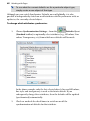
To change which attributes synchronize:
1.
Defaults flyout
Choose Synchronization Settings... from the
(Standard toolbar) to optionally select attributes (e.g., fill colour, Line
colour, Transparency, etc) from which new defaults will be made.
In the above example, only the last selected object's line and fill colour,
line style, and transparency is used as the future default. If you
subsequently change these attributes, then the defaults will be updated
(synchronized) automatically.
2.
Check or uncheck the check boxes to switch on or off the
synchronization of defaults for that attribute.
Working with Pages
49
To switch synchronize defaults off (for manual default control):
•
Uncheck Synchronize Defaults on the
Standard toolbar.
Defaults flyout of the
To set object defaults manually:
1.
With Synchronize Defaults disabled, create a sample object (the
object type matching the set of defaults you’re updating: line/shape,
artistic text object, connector, or dimension object), and alter it to use
the specific properties you plan to use as defaults.
- or Use an existing object that already has the right properties.
2.
Right-click the object and choose Update Defaults (or choose Update
Object Defaults from the Format menu).
When you update defaults from a shape, all default shape
properties, including shape text attributes, are reset at the same
time.
Shape text properties are stored along with other shape defaults,
such as line and fill. To avoid altering these settings when updating
shape text defaults, create a new sample shape and modify only its
text.
Normally, each time you close a document, object default settings are recorded
as "master settings" to be used in future documents. To stop DrawPlus from
recording the defaults as master settings, choose Tools>Save Settings... and
uncheck the Object Defaults box.
Resetting defaults
A reset of defaults is useful if you feel the need to get back to basics and return to
your original default settings.
•
Select Reset Object Defaults from the
Defaults flyout
(Standard toolbar). With no objects selected, this acts globally, i.e. it
resets all objects back to their default settings. With an object(s)
selected, it resets only those object types back to their default.
50 Working with Pages
Lines, Curves, and
Shapes
4
52
Lines, Curves, and Shapes
Lines, Curves, and Shapes
53
Selecting one or more objects
Before you can change any object, you need to select it using one of several tools
available from the top of the Drawing toolbar.
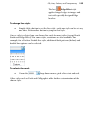
Pointer Tool
Click to use the Pointer Tool to select, move, copy, resize, or rotate objects.
Rotate Tool
Click to use the Rotate Tool to exclusively rotate an object around a centre
of rotation. You can also use the Rotate Tool to move or copy objects.
Node Tool
Click to use the Node Tool to manipulate the shape of objects, or move or
copy objects.
To select an object:
•
Click on the object using one of the tools shown above. For the Pointer
and Rotate Tools, small "handles" appear around the object indicating
selection.
For the Node Tool, editable nodes are displayed for lines—sliding
handles are additionally shown for adjustment of QuickShapes and
text. If objects overlap, click repeatedly (without double-clicking) until
the desired object is selected.
If you select an image with areas of transparency, you'll be able to
manipulate the image's outline, i.e. convert to curves, apply line
properties, effects, etc.
54
Lines, Curves, and Shapes
Selecting multiple objects
It is also possible to select more than one object, making a multiple selection
that you can manipulate as if it were one object, or turn into a grouped object.
To select more than one object (multiple selection):
1.
Choose the Pointer, Rotate or Node Tool.
2.
Click in a blank area of the page and drag a "marquee" box around the
objects you want to select.
Release the mouse button. All of the objects within the marquee box
are selected and one selection box, with handles, appears around the
objects. To deselect, click in a blank area of the page.
- or 1.
Click on the first object for selection.
2.
Press the Shift key down then click on a second object.
3.
Continue selecting other objects to build up your multiple selection.
Handles (or a bounding box, depending on the tool) appear around
the multiple selection.
To select all objects on the page:
•
Choose Select All from the Edit menu.
To add or remove an object from a multiple selection:
•
Hold down the Shift key and click the object to be added or removed.
Lines, Curves, and Shapes
55
Selection using a lasso
For more detailed multiple object selection, using a fixed marquee or Shift-select
may be too inflexible. Instead, you can draw an irregular-shaped lasso around
one or more objects in a complex design.
To select using a lasso:
1.
Choose the Pointer or Rotate Tool.
2.
With the Alt key pressed, draw a "lasso" around the objects you want
to select.
3.
Release the mouse button. All of the objects within the lasso region are
selected.
If attempting to lasso grouped objects remember to ungroup them
first.
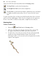
Drawing lines and shapes
Lines can be either straight or curved. They have properties like colour and
weight (thickness). When a line (or series of line segments) forms a complete,
enclosed outline, it becomes a new closed object called a shape. Because shapes
have an interior region that can be filled (for example, with a solid colour or a
bitmap), they have fill properties as well as line properties.
56
Lines, Curves, and Shapes
Choose one of the line tools shown below from the Drawing toolbar.
The Pencil Tool is used to sketch freeform lines.
The Straight Line Tool is used to draw straight lines.
The Pen Tool is used for drawing complex, combination curves and shapes
in a highly controlled way by using a series of "connect the dots" mouse
clicks.
As soon as you draw a line, or choose one of the line tools when a line is selected,
you'll see the line's nodes appear. Nodes show the end points of each segment in
the line. Curved lines usually have many nodes; straight lines have only two.
Drawing lines
To draw a freeform line:
Pencil Tool from the Drawing toolbar.
1.
Choose the
2.
Click once, then drag across the page, drawing a line as you go. The
line appears immediately and follows your mouse movements.
3.
To end the line, release the mouse button. The line will automatically
smooth out using a minimal number of nodes. Note the dots
indicating its nodes—at the two ends, and at each point where two line
segments come together.
Lines, Curves, and Shapes
4.
57
(optional) To set the degree of smoothing to be applied to the line
(and subsequent lines), set the Smoothness value on the context
toolbar above your workspace.
Click its right arrow to display a slider—drag right, then left. You’ll see
your drawn line—still selected—smooth out (with fewer nodes) as you
drag right, and become more jagged (with more nodes) as you drag
left. For the smoothest curves the next time you draw a freeform line,
leave the sliding arrow towards the right of the slider.
To draw a straight line:
1.
Straight Line Tool from the Drawing toolbar's Line
Click the
Tools flyout.
2.
Click where you want the line to start, and drag to another point while
holding down the mouse button, then release the mouse button. The
straight line appears immediately.
To constrain the angle of the straight line to 15° increments, hold
down the Shift key down as you drag. (This is an easy way to make
exactly vertical or horizontal lines.)
Any kind of open line (that is, one that hasn’t been closed to create a shape) can
be extended, and you can use any of the three line tools to do so. Use the Pointer
Tool and then the line’s drawing tool to resize or reshape lines once you've
drawn them.
58
Lines, Curves, and Shapes
To extend a line:
1.
Move the cursor over either of the end nodes, a small + cursor will
appear. Click at that location.
2.
The line that you drag out will be a continuation of the existing line, as
a new line segment.
To draw a curved line:
Pen Tool from the Drawing toolbar.
1.
Choose the
2.
From the displayed context toolbar, choose to create your
drawn segments in Smooth joins or Sharp joins creation mode. By
default, you'll be in Smooth joins mode (i.e., drawing Bézier curves
segment-by-segment). Sharp joins would create a zig-zag line without
curving through nodes.
3.
Click where you want the line to start (1).
4.
Click again for a new node and drag out a pair of control handles
which orbit the node (2). (Control handles act like "magnets," pulling
the curve into shape. The distance between handles determines the
depth of the resulting curved line.) Release the mouse button to create
your curve segment (3).
(1)
5.
(2)
(3)
To extend an existing line, click beyond the end of your current curve
to create a new node (thus creating another curve segment). Normally,
curve segments end in a symmetric (evenly rounded) corner (4), with
control handles locked together.
Lines, Curves, and Shapes
(4)
59
(5)
6.
However, you can press the Alt key while drawing the segment to
define a "cusp" or sharp corner (5). This locks the control handle on
the last created node. For more on line corners, see Changing nodes
and line segments.
7.
To end the line, press Esc or choose a different tool.
Drawing shapes
You can make a shape by closing a curve—extending a freeform line or a
segmented straight line back to its starting point. Shapes have an interior which
is filled with the current default fill (see Setting fill properties on p. 143) when
the shape is closed.
To close an existing curve (with a straight line):
1.
Select the curve with the Node Tool, Pencil or Pen Tool.
2.
Click
Close Curve on the context toolbar. A Straight segment
appears, closing the curve.
60
Lines, Curves, and Shapes
To close a curve (without new segment):
•
Select the curve with the Node Tool, and drag from an end node (note
the Node cursor), moving the line, onto the other end node (a Close
cursor will show); releasing the mouse button will create a shape.
If you're trying to draw a cartoon outline made up of many independent curves
(e.g., a cartoon ear, rose, etc.) you may want to fill each curve without closing it.
This is made easy by using the Fill-on-Create feature.
To fill an unclosed curve automatically:
•
Select the Pencil Tool, Pen Tool, or Paintbrush Tool.
•
Enable
from the context toolbar, and select a
suitable fill from the Colour tab. You'll also need to ensure Select-onCreate is enabled on the context toolbar (Freehand and Paintbrush
tools only).
•
Draw a freeform line, pen line, or brush stroke into a curve. The
resulting curve is closed automatically and filled with the current fill
colour.
Lines, Curves, and Shapes
61
Editing lines and shapes
To edit lines or shapes, you can manipulate their segments and/or nodes,
allowing you to:
•
Redraw part of a curve
•
Reshape a line (or curve)
•
Simplify a line (remove nodes)
•
Enhance a line (add nodes)
•
Change the type of node or line segment
•
Convert to straight line segments
•
Adjust a shape
•
Join two lines together
Redrawing part of a curve
With the Pencil Tool, it's easy to redraw any portion of a curve.
To redraw part of a selected curve:
1.
Select the line, then the
Pencil Tool. Hover the displayed cursor
on the line where you want to begin redrawing. The cursor changes to
indicate you can begin drawing.
62
Lines, Curves, and Shapes
2.
Click on the line, and a new node appears.
3.
Keep the mouse button down and drag to draw a new line section,
connecting it back to another point on the original line. Again, the
cursor changes to include a curve when you’re close enough to the line
to make a connection. When you release the mouse button, the
original portion is replaced by the newly drawn portion.
Reshaping a line
The main tool for editing lines and shapes is the Node Tool. In general, you first
use the Node Tool to select one or more nodes on the object, then use the
buttons on the tool's supporting context toolbar.
To reshape a curved line:
Node Tool on the Drawing toolbar.
1.
Click the
2.
Select any curved line on your page. The line’s nodes appear, and the
context toolbar also pops up.
3.
Hover over a segment and drag the segment to form a new curve
shape.
Lines, Curves, and Shapes
63
- or Select nodes and drag. Selection can be by one of the following
methods:
Hover over a single
node and click to
select the node.
Shift-click for
multiple nodes.
drag out a marquee
to select multiple
neighbouring
nodes
drag out a lasso
(with Alt key
pressed) to select
multiple nodes
otherwise difficult
to select via a
marquee.
Once selected, a node becomes highlighted and control
handles for the adjacent line segment(s) will appear.
Note that each segment in the line has a control handle at either end, so when
you select an end node or interior node, indicated below, you'll see either a
control handle on each selected end node (one segment) or a pair of handles at a
selected interior node (two segments), respectively, i.e.
64
Lines, Curves, and Shapes
4.
Drag any selected node to reshape adjacent segment(s). All selected nodes
move in the same direction, so you can reshape the curve in complex ways
by selecting specific nodes. Shift-drag to constrain the movement to
horizontal or vertical.
5.
Drag one or more control handles to produce very precise changes in the
curvature of the line on either side of a node. You can shorten or lengthen
the handles, which changes the depth of the curve (that is, how far out the
curve extends), or alter the handle angle, which changes the curve’s slope.
When using the Pen Tool, pressing the Ctrl key while clicking a node
lets you edit the curve directly. This saves having to jump back to
the Node Tool. You can't edit multiple nodes simultaneously.
By changing the type of node you can change how the adjacent
segments behave.
As a shortcut when selecting nodes, you can press Tab or Shift-Tab
to select the next or previous node along the line (following the
order in which nodes were created).
Simplifying or enhancing a line
The more nodes there are on a line or shape, the more control over its shape you
have. The fewer nodes there are, the simpler (smoother) the line or shape. You
can adjust the Smoothness to refine the curve most recently drawn (as long as
the line is still selected). It is also possible to add or delete nodes to simplify or
enhance curves, and even clean curves (removing unnecessary nodes
automatically).
Lines, Curves, and Shapes
65
To adjust the smoothness of the most recent pencil line:
Pencil Tool and draw a freeform line.
1.
Choose the
2.
Click the right arrow on the Smoothness option and drag the
displayed slider left to increase the number of nodes (you can also add
absolute values into the input box).
3.
To make the curve less complex, i.e. smoother, drag the slider right to
decrease the number of nodes.
To add or delete a node:
•
To add a node, click along a line segment with the Node Tool or Pen
Tool to add a new node at that point. The new node will be created
and will be selected (complete with attractor nodes as necessary).
•
To delete a node, select the line with the Node Tool then the
node itself and click the Delete Node button on the context toolbar (or
press the Delete key). The node will be deleted, along with any
associated attractor nodes, and the line or shape will jump to its new
shape. With the Pen Tool selected, you can also delete a node by
clicking on it.
You can also use the Node Tool to reposition the nodes, and reshape the line or
shape, by dragging on the new handles.
Changing nodes and line segments
Each segment in a line has a control handle at either end, so at each interior or
"corner" node (where two segments join) you'll see a pair of handles. The
behaviour of these handles—and thus the curvature of the segments to either
side—depends on whether the node is set to be sharp, smooth, symmetric, or
smart. You can quickly identify a node's type by selecting it and seeing which
button is selected in the displayed context toolbar. Each type's control handles
behave differently as illustrated below.
66
Lines, Curves, and Shapes
To change one or more nodes to a different type:
1.
Select the object with the Node Tool, followed by the node(s) you
want to change.
2.
Click one of the node buttons (described below) on the displayed
context toolbar.
A Sharp Corner means that the line segments to either
side of the node are completely independent so that the
corner can be quite pointed.
A Smooth Corner means that the slope of the line is the
same on both sides of the node, but the depth of the two
joined segments can be different.
At a Symmetric Corner, nodes join line segments with
the same slope and depth on both sides of the node.
Note: Normally, Custom segments you draw with the Pen
Tool end in a symmetric corner.
Smart Corner nodes automatically determine slope and
depth for a rounded, best-fitting curve. If you attempt to
adjust a smart corner's handles, it reverts to a symmetric
corner. You can always reset the node to smart—but to
maintain smart nodes, be careful what you click on!
You can also use the context toolbar to define a line segment as either straight or
curved.
Lines, Curves, and Shapes
67
To change a line segment from straight to curved, or vice versa:
1.
With the Node Tool, select the leading node of the line segment (the node
nearer the start of the line).
2.
Then, either:
•
To make a line segment straight, click
Straighten Line on the
context toolbar. The selected segment immediately jumps to a
straight line.
- or -
•
To make a line segment curved, click one of the node buttons on
the context toolbar: Sharp Corner, Smooth Corner, Symmetric
Corner, or Smart Corner. You can then adjust the curvature of
the newly created curved segment.
To convert to straight lines:
1.
With the Node Tool, select the curve.
2.
Convert to Straight Lines. The
From the context toolbar, choose
curve segments are replaced by straight line segments throughout the
line.
Adjusting a shape
As described on p. 59, you can easily turn a curve into a shape by connecting its
end nodes. You can go the other way, too—break open a shape in order to add
one or more line segments.
To break open a line or shape:
1.
With the Node Tool, select the node on the closed curve where you
want the break to occur.
2.
Break Curve on the context toolbar so that the line will
Click
separate. A shape will become a line, with the selected node split into
two nodes, one at each end of the new line.
3.
You can now use the Node Tool to reposition the nodes and reshape
the line by dragging on the handles.
68
Lines, Curves, and Shapes
When you first break a curve the two nodes are in exactly the same
location and so the curve may still look as if it is connected. If you
drag one of the red node ends away you will quickly see the
separation.
Joining lines together
You can connect any two straight or curved lines to form a new line.
To join two lines together:
1.
Select both lines by Shift-clicking with any selection tool.
2.
Choose Join Curves from the Tools menu. The end control node of
one line is connected with the start control node of the other.
Using QuickShapes
QuickShapes are pre-designed
objects that you can instantly add to
your page, then adjust and vary using
control handles. QuickShapes are
added from a flyout containing a
wide variety of commonly used
shapes, including boxes, arrows,
hearts, spirals and other useful
symbols.
To create a QuickShape:
1.
QuickShape button on the
Click the down arrow on the
Drawing toolbar, then select a shape from the flyout. The button takes
on the icon of the shape you selected.
2.
At your chosen cursor position, either:
•
Double-click to place a default-sized QuickShape.
- or -
Lines, Curves, and Shapes
•
69
Click and drag on the page to draw out your QuickShape to a
chosen size (use the Shift key to lock the aspect ratio; the Ctrl key
to scale from its centre point; or both together).
New QuickShapes adopt the currently set line and fill in DrawPlus.
All QuickShapes can be positioned, resized, rotated, and filled. What's more, you
can "morph" their designs. For example, dragging the handles on a Quick
Polygon will change the number of sides to make a triangle, pentagon, hexagon,
or other polygon.
To adjust the appearance of a QuickShape:
1.
Click on the QuickShape to reveal sliding handles around the shape.
These are distinct from the "inner" selection handles. Different
QuickShapes have different handles.
2.
Drag any handle to change the appearance of the QuickShape.
For example, by dragging the top sliding handle to the right on the pentagon
below will quickly produce an octagon:
You can also use the Line tab and Swatch tab to alter any object's line/fill
properties after it has been drawn.
70
Lines, Curves, and Shapes
Using the Gallery
The Studio's Gallery tab contains pre-built design objects and elements you'd
like to reuse in different drawings. Arts and Crafts, Cartoons, Connecting
Symbols (for family trees, electronics, and computers), Layout Symbols (for
garden and home), and ShapeArt are all folders under which various categories
(or further sub-folders) are stored. When you install the DrawPlus X3 Resource
CD the Gallery tab also includes further categories (Curriculum and Business)
for your use.
The Gallery tab has two
parts: (1) an upper
Folder/Categories
drop-down menu and
(2) a lower Designs
window where you can
select and drag a copy of
the design onto your
page.
The Gallery tab also lets you store your own designs in the My Designs section if
you would like to reuse them—the design is made available in any DrawPlus
document. You can add and delete your items within each category, with the
option of naming elements to facilitate rapid retrieval.
New design categories can be added to any design folder which exists under the
user's My Designs category (but not under any read-only pre-defined category).
You can rename or delete any design by right-clicking on the design thumbnail.
To use a design from the Gallery:
•
Drag any preset design directly onto the page. The Gallery retains a
copy of the design until you expressly delete it. You can modify, then
drag the design back into your own custom category.
Lines, Curves, and Shapes
71
To view your Gallery:
•
Click the Studio's Gallery tab.
•
Select a folder or category from the drop-down menu. The items from
the folder's first listed category are displayed by default.
To add, delete, or rename design folder (or category):
1.
Right-click in the drop-down menu and choose Add Folder... (or Add
Category..., Delete Category/Folder, or Rename Category/Folder....
2.
For adding and renaming, use the dialog to enter and/or confirm your
change.
To add, delete, or rename design categories:
1.
Right-click in the Categories list and choose Add Category..., Delete
Category/Folder, or Rename Category/Folder....
2.
For adding and renaming, use the dialog to enter and/or confirm your
change.
To copy an object into the Gallery:
1.
Display the Gallery tab's My Designs category (or sub-category of
that) where you want to store the copy.
2.
Drag the object from the page and drop it onto the gallery.
3.
You'll be prompted to type a name for the design. (You can name or
rename the design later, if you wish.) By default, unnamed designs are
labeled as "Untitled."
4.
A thumbnail of the design appears in the gallery, labelled with its
name.
To delete or rename a design:
•
Right-click its gallery thumbnail and choose Delete Design... or
Rename Design... from the submenu.
72
Lines, Curves, and Shapes
Converting a shape to editable curves
The conversion of QuickShapes to curves provides you with a starting point for
your own shapes, whereas converting text to curves is one way of incorporating
editable letter-based shapes into designs.
To convert an object into curves:
1.
Select your QuickShape or text object.
2.
Click
3.
Edit the curve outline using the Node Tool.
Convert to Curves on the Arrange tab.
However they were created, all converted objects behave in a similar manner.
For example, you can create some text with the Artistic Text Tool, convert it to
curves, then use the Node Tool to edit the curves that make up the letters, just as
if you had drawn the letter shapes by hand using the line tools.
The conversion process loses all of the special properties inherent in
QuickShapes and text.
Check Clean Curves in Tools>Options>General to automatically reduce the
number of nodes during convert to curve operations—this makes editing a little
easier!
Lines, Curves, and Shapes
73
Applying perspective
The Perspective Tool, like the adjacent Envelope Tool, produces an overall
shape distortion. But while the Envelope effect stretches the object as if it were
printed on a rubber sheet, perspective gives you the visual impression of a flat
surface being tilted (or skewed) in space, with an exaggerated front/back size
differential.
To apply a perspective effect:
1.
Select an object and click
Perspective Tool on the Drawing
toolbar. The Node Tool becomes the active tool and an adjustment
slider appears above the object.
2.
“3D” cursor over the selected object or drag the special
Drag the
adjustment slider handle left or right to see it respond by tilting in all
sorts of orientations. Use Undo if you’re not happy with a particular
adjustment.
- or From the context toolbar, select an item from the
flyout closest to the effect you’re after. The first item, User Defined
perspective, retrieves the last drawn custom perspective shape used in
your current DrawPlus session. You can still use the cursor and
handles for adjusting perspective.
74
Lines, Curves, and Shapes
Applying envelopes
An envelope distortion is one that you can apply to any object to change its
shape without having to edit its nodes. You can use envelopes to bend text into a
wave, arch, trapezoid, or just about any other shape. You can edit envelopes into
custom shapes and apply them to other objects for corresponding effects.
With the Envelope Tool, an object’s nodes can be moved in order to create
custom envelopes or to allow preset envelopes to be applied to the selected
object. The displayed context toolbar, shown while the tool is active, offers
various options to customize the envelope—envelope shape, line colour, weight,
and style can all be altered. It also lets you pick from a range of pre-defined
envelopes of various shapes, remove the selected object's envelope or apply curve
adjustments on the envelope's boundary.
To apply an envelope:
1.
Select the object(s) you want to be enveloped.
2.
Click
3.
From the context toolbar, select a preset from the
flyout. The first item, User Defined envelope, retrieves the last drawn
custom envelope shape used in your current DrawPlus session.
Envelope Tool on the Drawing toolbar.
To remove an envelope:
1.
Select the envelope with the Envelope Tool.
2.
Click
from the Envelope context toolbar.
To create/edit your own envelope:
You can create an envelope or edit any of the preset envelopes once they have
been applied by dragging the nodes and handles accordingly.
Lines, Curves, and Shapes
•
75
Select the object(s) with the Envelope Tool. DrawPlus automatically
selects the Node tool when an envelope is applied. The Node Tool
along with the displayed curve buttons on the Envelope context
toolbar lets you reshape the envelope by dragging its corner nodes and
attractor nodes, as when editing curved lines. (To review these
concepts, see Editing lines and shapes on p. 61.) The only difference is
that you cannot add or delete corner nodes to an envelope. Envelopes
always have exactly four line segments, one on each side.
Connectors
Connectors are special lines that you can anchor to objects, where they remain
attached even if one or both objects are moved or resized. Using connectors, you
can easily create dynamic diagrams and charts that show relationships, such as
family trees, organization charts, and flow charts. If you need to rearrange the
elements, the connections are preserved.
Each DrawPlus object has default connection points, displayed whenever you
select one of the connector tools and hover over the object. These default points
(which can't be moved or deleted) are called Auto Select points.
76
Lines, Curves, and Shapes
To create a connection:
1.
Select
Connector Tool on the Line Tools flyout (Drawing
toolbar). Hover over an object so that default Auto Select connection
points become visible, e.g. as on the left Quick Rectangle:
2.
From the context toolbar, select
3.
Click the connection point on the right edge midpoint of the left
shape. Drag to the right and release the mouse button when the
pointer is over the connection point on the left edge midpoint of the
right shape. (You’ll see a box appear around the point when a
connection is imminent.) A direct connector will appear between the
two connection points.
4.
Select the right-hand shape and drag to a new position with the
Pointer Tool; the connection points vanish, but the connector
remains. The connector follows!
Direct Connector Tool.
Lines, Curves, and Shapes
77
Connector types
The
Connector Tool, when selected, offers various types of connector tool
on the Connectors context toolbar situated above the workspace.
Choose the Direct Connector Tool to draw a single,
straight-line connector between any two connection
points.
Choose the Right Angle Connector Tool for a
connector with only vertical and horizontal segments
(the connector shape is made up of right angles)—for
example, if you're creating a flow chart, organization
chart, or tree diagram.
Choose the Auto Connector Tool for an adaptable
connector that intelligently adjusts its shape to route
around "obstructive" objects. Unlike the other
connectors, Auto connectors automatically form
"bridges" when crossing each other, so they're perfect
for complex diagrams with interwoven pathways.
The context toolbar is also used to adjust a connector’s line weight,
line end, colour and style.
You can create your own additional custom connection points,
created with the Connection Point Tool, which can be placed
anywhere on an object.
78
Lines, Curves, and Shapes
Using Brushes
5
80
Using Brushes
Using Brushes
81
Selecting brushes
DrawPlus supports a wide range of brushes, all capable of producing:
natural
brush effects:
natural media
(charcoal, pastel,
pen, pencil, paint,
watercolour) or
photo brushes
(stitching).
spray and
photo brush
effects:
airbrushes,
grunge, special
effects (glitter,
smoke,
snowflakes, and
more), rope,
chain, zippers.
Painting inherits the principles of Drawing lines and shapes (see p. 55). The
drawing freedom of the Pencil Tool is adapted for brushwork using the
dedicated Paintbrush Tool. You can pick up colour for your brushes as you
would for other object, by simply selecting the Paintbrush Tool, choosing your
brush type from the Brushes tab and picking a brush colour from the Colour or
Swatch tab.
Brushes based on bitmaps cannot be recoloured.
82
Using Brushes
The Brushes tab lets you
select a brush type from
a range of natural
(opposite), spray or
photo-based categories.
You can also view
brushes currently being
used in your document,
and edit brushes or
create your own brushes
(see online Help).
Natural and spray brush types are indicated by
symbols, respectively.
and
To make sense of all the brush types available to the user, the preset brushes are
stored under a series of pre-defined categories under the name Global—the
brushes are available to all DrawPlus documents currently open. The Document
category shows the brush types currently in use in the DrawPlus drawing and is
used to “bookmark” brushes for easy reuse in the future.
At some point, you may want to edit, copy or create your own natural stroke or
spray brush type. See online Help.
Brush strokes can be applied directly to the page by using your mouse or tablet;
the latter method is ideally suited for applying customizable pressure-sensitive
strokes to your drawing. However, painting with the mouse still provides a
viable alternative to the tablet. Pressure sensitivity is simulated by use of readymade customizable pressure profile presets.
Using Brushes
83
Applying brush strokes
The
Paintbrush Tool is used exclusively to
apply brush strokes to the page. The tool is used in
conjunction with the Brushes tab, and a supporting
context toolbar.
To apply a brush stroke:
Paintbrush Tool from the Drawing toolbar.
1.
Select the
2.
Display the Brushes tab and choose a brush from a category (use the
drop-down list for different categories).
3.
Select a Colour, Width, or Opacity from the Brush context toolbar.
Brushes based on bitmaps cannot be recoloured.
4.
(Optional) From the context toolbar, adjust Smoothness (to set how
smooth your stroke is applied) via a slider.
84
Using Brushes
5.
(Optional) Enable
to leave the brush stroke
selected on the page or, if disabled, leaves it deselected.
6.
(Optional) Enable
to fill the unclosed curve
produced with the brush stroke with a default fill colour.
7.
With the
brush cursor drag a brush stroke across your page.
After this first brush stroke, there are two ways in which you are likely to paint
subsequently, depending on the extent to which you plan to edit brush strokes as
you go. To assist you, the Select on Create button on the Brushes context
toolbar can be used:
•
Edit then Paint. With the button disabled, the brush stroke is laid
down and is immediately deselected. The stroke needs to be reselected
to perform any editing. Use when you’re happy to set all the brush
properties (colour, brush type, width, etc) before painting (as above),
especially if you intend to paint repeatedly with the same brush stroke.
•
Paint and Edit. With the button enabled, a painted brush stroke will
remain selected, meaning that the brush stroke can be fine-tuned via
the context toolbar immediately. Use when changing your brush
properties frequently, e.g. when adjusting a brush stroke’s colour,
width, opacity or shape. The ESC key deselects the current brush
stroke.
Trouble applying colour to brush strokes? Remember to select the
line swatch on the Colour tab.
Setting Brush Defaults
See Updating defaults on p. 47.
Editing brush strokes
It's possible to alter any previously draw brush stroke with respect to its
properties, brush type, and shape.
Using Brushes
85
To change brush stroke properties:
•
Use the Brushes context toolbar to adjust the properties of a drawn
brush stroke once applied to your page.
To change brush stroke type:
1.
Select the brush stroke.
2.
Go to the Brushes tab and select firstly a brush category then a brush
type from the displayed gallery. The brush stroke adopts the newly
chosen brush.
Brush types currently applied to your brush strokes are handily
listed in the Document folder of the Brushes tab.
To change the shape of your brush stroke:
A brush stroke possesses very similar characteristics to a plain line. Any
brush stroke can therefore be edited, extended, or redrawn with the Node Tool
(Drawing toolbar) just as for a straight or curved line (see Editing lines and
shapes on p. 61). Use for fine-tuning your brush strokes after application.
Pressure sensitivity
Along with a brush's natural characteristics (its bristles, shape, and size),
pressure sensitivity also plays a major part in how a brush is applied to your
page. The extent to which a brush is applied is at the heart of an artist’s creative
ability. A heavily applied brush could help to convey strong imagery (e.g.,
moods), whereas a brush applied more lightly may indicate a more subtle effect.
In DrawPlus’s world we apply pressure by using a pressure-sensitive device (a
tablet and pen) and control how that pressure affects your brush stroke in
DrawPlus’s Pressure tab. This tab is used to apply different pressure profile
presets, create your own profiles from scratch and adjusts how the brush’s width
and transparency changes as it responds to pressure. The maximum and
minimum pressure can also be controlled via the tab—your brush strokes can
appear more subtle or striking as a result.
86
Using Brushes
The pressure chart may appear a little daunting at first! It becomes a lot clearer if
you imagine the chart when it is superimposed over the brush itself —it
represents one half of a brush stroke along its entire length exactly. Of course,
the same profile shape will be mirrored on the lower half of the stroke.
To apply a pressure profile:
1.
Expand the Pressure tab at the bottom right of your screen, and choose
a pressure profile from the drop-down menu.
The pressure chart updates to reflect the chosen profile.
2.
Apply a brush stroke to the page. This will adopt the chosen pressure
profile.
The profile is maintained until you reset it or pick another profile from the
preset list.
Using Brushes
87
To create a new pressure profile:
. This sets the pressure chart back to
1.
Click
default.
2.
A turquoise line runs along the maximum pressure line at the top of
the chart. Click on this line (the cursor changes) and drag downwards,
moving the displayed red node into your chosen position. You now
have a blue curve which represents the pressure profile.
3.
Repeat the process for the number of nodes that you want to add to
make up the profile.
Edit an existing pressure profile from the preset drop-down menu to
create profiles quickly.
You can then save the current pressure settings to your own saved pressure
profile—this allows you to store and reapply your settings at any point in the
future.
To save a new pressure profile:
•
Click on the
Tab Menu button and select Add Pressure Profile.
Your new profile is automatically added to the bottom of the pressure profile
preset drop-down list.
To delete a pressure profile:
Tab Menu button and select Manage Pressure
1.
Click on the
Profiles....
2.
In the dialog, select the pressure profile for deletion and click the
Delete button.
Altering brush width and opacity with pressure
For subtle brush pressure control, DrawPlus can vary the extent to which pen
pressure can alter a brush’s original width and opacity. This is expressed as a
percentage of the original brush Width and Opacity values shown in the
Brushes context toolbar. Imagine the end of your brush stroke tapering off or
getting fainter as it lifts off the page—the concept is simple!
88
Using Brushes
You can set the degree to which width and opacity changes either independently
or in combination. Let’s look at some examples... based on a Default brush
called "Circle". The example doesn’t use a natural media texture so the concept is
illustrated more clearly. We’ll use a pressure profile available from the preset
drop-down menu for all examples.
Here’s how the degree of width/opacity changes the brush stroke appearance.
The first example shows the default behaviour when brush pressure is applied.
These settings are adjusted independently and are not stored with the pressure
profiles.
Using Brushes
89
To adjust brush width or opacity with pressure:
1.
Select a previously drawn brush.
2.
In the Pressure tab, pick a pressure profile from the drop-down menu.
3.
Enter a
Width or
Opacity value by setting a percentage value
in the input box, using the slider or using the up/down arrows. The
lower the value the less the pressure effects the brush width or opacity,
i.e. a value of 50% will apply half the brush width or opacity under
pressure.
You can set the pressure variance, i.e. the degree to which you apply brush
pressure, via the Pressure tab by increasing/decreasing the lower or upper limits
of the pressure chart. (See online Help for more information).
90
Using Brushes
Working with Text
6
92
Working with Text
Working with Text
93
Entering text
You can create different types of text in DrawPlus, i.e. Artistic Text, Frame
Text, or Shape Text, all directly on the page.
Artistic Text
Frame Text
Shape Text
It's easy to edit the text once it's created, by retyping it or altering properties like
font, style, and point size.
In general, artistic text (as an independent object) is better suited to decorative
or fancy typographic design, frame text is intended for presenting text passages
in more traditional square or rectangular shaped blocks; shape text lends itself so
well to blocks of body text where shape and flow contribute to the overall layout.
Artistic text behaves more independently than Shape and Frame Text and its
individual letters can be stretched, rotated, sheared, enveloped, and combined
with other objects. Shape text lacks a line property, but it conforms to the
containing shape, and you can achieve unique text flow effects by varying the
container’s properties. (See Fitting text to frames and shapes for details.)
Default settings (p. 47) are stored separately for artistic text and frame text.
To enter new artistic text:
Artistic Text on the Drawing toolbar's Text flyout.
1.
Select
2.
To create artistic text at the current default point size, click where you
want to start the text.
- or -
94
Working with Text
For artistic text that will be automatically sized into an area, click and
drag out the area to the desired size.
3.
To set text attributes (font, size, etc.) before you start typing, make
selections on the Text context toolbar. For colour, set the Line/Fill
swatches on the Studio's Colour or Swatch tab.
4.
Start typing.
To create frame text:
Frame Text on the Drawing toolbar's Text flyout.
1.
Select
2.
From the positioned cursor, either:
•
Double-click on the page or pasteboard to create a new frame at a
default size.
- or -
•
Drag out a frame to your desired frame dimension.
3.
(Optional) Set text and colour attributes as for artistic text before you
start typing.
4.
Start typing within the frame.
To enter new shape text:
1.
Create a QuickShape either from the QuickShape flyout or by closing a
drawn line.
2.
With a shape still selected, just start typing.
For existing shapes without shape text, select the shape, then click in its centre,
then start typing.
Working with Unicode text
On occasion, you may wish to import text in a foreign language, e.g. you may
want to include a foreign quote in its original language. To work outside the
standard ASCII character set, DrawPlus allows Unicode characters to be pasted
(using Edit>Paste Special...) from the clipboard into your drawing.
Working with Text
95
To retain formatting, use "Formatted Text (RTF)" or for plain text use
"Unformatted Unicode Text". For the latter, if your imported text appears as
blocks instead, remember to apply a Unicode font such as Arial Unicode MS to
fix the formatting.
Editing text
Once you've entered either artistic, frame or shape text (see Entering text on p.
93), you can retype it and/or format its character attributes (font, point size,
bold/italic/underline, etc.), paragraph properties, and text flow. Text objects
have graphic properties, too: artistic text behaves like an independent graphic
object (it can be scaled), while shape or frame text conforms to its container or
frame.
Artistic text, text frames, and shapes containing text can all be rotated, skewed,
moved, and copied. You can also apply line and fill colour independently, brush
strokes/edges, or apply opacity and transparency effects, for interesting text
effects.
Colour can be applied to selected text as a solid, gradient or bitmap fill—for a
solid fill, simply select one or more characters and apply a solid colour from the
Studio's Colour tab (ensuring the fill swatch is set) or the Character dialog. See
Setting fill properties on p. 143.
For a gradient or bitmap fill, use the Studio's Swatch tab. See p. 155 or p. 159,
respectively.
Similarly, opacity is applied from the Colour tab (see p. 162); gradient and
bitmap transparency from the Transparency tab.
96
Working with Text
Retyping text
You can either retype artistic, frame or shape text directly on the page, or use the
Edit Text window—great for managing large amounts of text (overflowed shape
text or otherwise) in a simple word processing environment.
To retype text on the page:
1.
Artistic Text (from the Drawing
Select the object and then select
toolbar's Text flyout), in either order.
2.
Type new text at the selection point or drag to select text, then type to
replace it. To cut, copy, and paste, use the toolbar buttons or standard
Windows keyboard shortcuts.
To create a new line:
•
At the position you want to start a new line, press the Enter key.
Formatting text
You can change text formatting (character, paragraph, bullets/numbering and
text flow properties) either directly on the page or via the Edit Text window.
In addition, artistic text characters have line properties, expanding their creative
possibilities.
To format selected text on the page:
1.
Use the
Pointer Tool to select the text you want to change.
Alternatively, drag select on any text with
Drawing toolbar's Text flyout).
2.
Artistic Text (from the
Use the Text context toolbar to change text properties (font, point size,
bold/italic/underline, text alignment, bullets and numbering, levels,
and text fitting).
- or Choose Character..., Paragraph..., Tabs..., Bullets and Numbering...,
or Text Flow... from the Format menu (or the right-click menu).
Working with Text
The
text.
97
Node Tool can be used for special adjustments on artistic
For greater control over the shape of the artistic text characters, try
converting the artistic text to curves. As curves, you can position
every character individually and even edit the character shapes,
exactly as if you had drawn the character shapes by hand using the
line tools. For details, see Converting a shape to editable curves on
p. 72.
Fitting text to frames and shapes
Text overflow
If there's too much text to fit
into a text frame or shape,
the
button
appears beneath the shape;
DrawPlus stores the
overflowing text in an
invisible overflow area.
To make all the text fit you might edit the story down to allow text to fit in the
frame or shape. However, scaling the text to fit may be preferable where you can
scale the shape or frame text size so it fits exactly into the available frame.
To scale the frame or shape text:
•
Click
to autofit the frame or shape text to its container.
AutoFit first applies small point size changes, then small leading
changes, then adjustments to the paragraph space below value, until
the text fits. Other settings are not affected.
- or -
•
Use
Autofit on the Text context toolbar.
98
Working with Text
For incremental scaling, use the
on the same toolbar.
Enlarge Text or
Shrink Text buttons
Positioning
•
Vertical alignment (right-click Text>Text Flow...) moves existing
text to the Top, Bottom, or Centre of the container (alternatively you
can justify text vertically). The setting anchors a particular part of the
object—for example, a "Top" setting anchors the top line and forces
new text to come in below, while a "Bottom" setting anchors the
bottom (most recent) line and pushes previous lines up as you type
new lines.
•
To add white space around your text, you can indent text from the
frame or shape edge via right-click Text>Text Flow.... Values can be
set to indent from Left, Right, Top and/or Bottom.
Resizing
•
You can resize frame or shape text (change its point size)
automatically when resizing frame and shapes. First make sure the
Scale text with object box is checked in the Text flow dialog (rightclick Text>Text Flow...) then drag a corner of the selected text object.
Fitting text to a path
Use the Curve Text
Wizard or text context
toolbar's Curve Text
flyout to make artistic
text conform to a curved
baseline such as a circle,
spiral, arc, or a drawn
curve.
Working with Text
99
To flow text along a curve:
Either:
1.
If you want to use an existing text object, select the object first.
Otherwise, you can enter text in the wizard.
2.
Go to Tools>Curve Text Wizard.
3.
After the first screen, enter text to be placed on the curve. This is not
shown if text has already been selected on the page.
4.
In the second screen, if an object or outline has already been selected
the Use Current Selection option will be checked. Uncheck if you
want your text to flow along one of the available preset curves then
pick a curve on which the text will be placed.
5.
Click Finish to close the wizard. If using an existing text object, the
text will be placed on the curve, line or shape. For text entered via the
wizard, you'll have to click to add text of a default size to the page (or
drag out the text on the page for a custom size).
- or 1.
Select your artistic text.
2.
From the context toolbar, click the down arrow on the
button and select a preset curve from the drop-down menu on which
the text will flow.
You can edit the baseline curve with the Node Tool.
Adding dimension lines and labels
DrawPlus lets you add dimension lines with text labels showing the distance
between two fixed points in a drawing, or the angle formed by three points. For
example, you can draw a dimension line along one side of a box, measuring the
distance between the two corner points. If you resize the box, the line
automatically follows suit, and its label text updates to reflect the new
measurement.
100
Working with Text
You’ll find dimension lines indispensable for planning garden designs (e.g., a
garden gazebo plan above), technical diagrams, floor plans, or any drawing
where exact measurements and scale are important.
Although they can be drawn anywhere on the page, dimension lines are at their
most accurate when attached to connection points on objects (see p. 77). When
you choose one of the Dimension tools, connection points on page objects
become visible on hover over, i.e. when you move the mouse pointer directly
over a connection point, a small box appears around it when a connection can
be made. For more information on connection points, see Working with
connectors on p. 75.
To draw a dimension:
1.
Dimension Tool from the Drawing toolbar’s Line
Select the
flyout. (The flyout shows the icon of the most recently selected tool.)
2.
Either, for a linear dimension (vertical, horizontal, or slanted), click
the respective tool from the Dimension context toolbar:
•
Vertical Dimension Tool
•
Horizontal Dimension Tool
•
Slanted Dimension Tool
Working with Text
101
Click where you want to start the dimension line (e.g., on a connection
point), then drag and release the mouse button where you want to end the
line (maybe on another connection point). The illustrations below show the
result of dragging between connection points A and B.
A pair of parallel extension lines
appears from the two points.
Between the two extension lines,
the dimension line and its label
"float." Click the blue line box to
position the floating line and
label; drag the red circle within.
Release when the line and label
are where you want them. (You
can always change the positions
later.) Click away to reveal the
dimension line.
- or For an angular dimension, click the
Angular Dimension tool
then click on a point along one side of the desired angle, then drag
and release the mouse button at a point along the other side of the
angle (points A and B in the illustration below). Click again at the
vertex of the angle (point C below). These three points define the
starting and ending sides of the angle. Between the two sides, the
angle's arc and its label "float," awaiting final positioning. Click again
to position the floating elements.
Angles are measured anti-clockwise from the starting to the ending
side, so choose your three nodes accordingly.
102
Working with Text
To complete the dimension line, move the mouse again to position the
floating line or arc and its label—note that they respond independently—
and click when they are where you want them. (You can always change the
positions later.) The dimension line appears.
Node Tool to freely
Once you've added a dimension line, you can use the
adjust node and label positions if necessary. Use Format>Character to change
the font, font size, colour and style of the label text. You can also format the line,
including line colour, width, style, or adjust the level of precision with the
Dimensions context toolbar.
Spell-checking
The Spell Checker lets you check the spelling of selected artistic, frame, or shape
text, as well as all text sequentially throughout your DrawPlus document.
Multilingual spell checking is supported by use of over 10 spelling dictionaries.
By default, the spelling dictionary is set on program install (according to
Windows Control Panel's Regional and Language Options), i.e. your dictionary
is set to the operating system's language.
Any detected spelling
mistakes or any word not
present in the language's
dictionary will appear
underlined with a red
zigzag line.
Alternatively, the Spell Checker can be launched to run through your document,
spell checking as it goes.
Working with Text
103
To enhance the power of spell checking, you can add words to the current
dictionary that spell checking doesn't yet know about. These could include
uncommon words, technical words, or even acronyms and abbreviations.
To check spelling:
1.
(Optional) To check specific text, select the artistic, frame or shape
text in advance.
2.
Choose Check Spelling... from the Tools menu.
3.
(Optional) In the dialog, click Options... to set preferences for
ignoring words in certain categories, such as words containing
numbers or upper/mixed case characters.
4.
Enable Check currently selected objects only or Check all text radio
buttons depending on if you want to spell check text selected
previously or all text.
5.
Click Start to begin the spelling check.
When a problem is found, DrawPlus highlights the problem word on the page.
The dialog offers alternative suggestions, and you can choose to Change or
Ignore this instance (or all instances with Change All or Ignore All) of the
problem word, with the option of using Add to add the problem word to your
dictionary. DrawPlus will also let you Suggest an alternative.
6.
Spell checking continues until you click the Close button or the spellcheck is completed.
To change to a different spelling language:
1.
Go to Options... from the Tools menu, and select Spell Checker.
2.
Choose a different Language from the drop-down menu, and click
OK.
Spell checking can be turned off by selecting "None" as a language
type—this could be useful when working with text containing an
unmanageable number of unusual terms (perhaps scientific or
proprietary terminology).
104
Working with Text
To check the spelling of a single word:
1.
With Underline mistakes as you type checked and a language selected
(in Tools>Options>Spell Checker), select in a marked word, then
right-click. You'll see alternative spellings on the context menu.
2.
To replace the word, choose an alternative spelling from the menu.
3.
To tell DrawPlus to ignore (leave unmarked) all instances of the
marked word in the document, choose Ignore All.
4.
To add the marked word (as spelled) to your personal dictionary,
choose Add to Dictionary. This means DrawPlus will ignore the word
in any drawing.
You can also run the Spell Checker from the context menu by choosing Check
Spelling....
You can make your own custom dictionary via
Tools>Options>Spelling Dictionary.
Working with
Objects
7
106
Working with Objects
Working with Objects
107
Copying, pasting, cutting, and deleting objects
To copy one or more objects to the Windows Clipboard:
1.
Select the object(s).
2.
Click the
Copy button on the Standard toolbar.
If you're using another Windows application, you can usually copy and paste
objects via the Clipboard.
To paste an object from the Clipboard:
•
Click the
Paste button on the Standard toolbar.
The standard Paste command inserts a clipboard object onto the page.
To select the type of object to be pasted from the Clipboard, choose
Paste Special... from the Edit menu.
To cut one or more objects to the Clipboard:
1.
Select the object(s).
2.
Click the
Cut button on the Standard toolbar.
The object is deleted from the page and a copy is placed on the Windows
Clipboard.
To delete one or more objects:
•
Select the object(s) with the Pointer, Rotate or Node Tool and press
the Delete key.
Cloning an object
DrawPlus lets you "clone" or duplicate objects easily using drag-and-drop, and
duplicate multiple copies of any object. For duplication, a copy is displayed at
the new location and the original object is still kept at the same position—your
new copy also possesses the formatting of the original copied object.
108
Working with Objects
Making duplicates
•
Select the object while holding down the Ctrl key, then drag the copied
object to a new position.
Use duplication when rotating or shearing an object—the result is a
new copy at a new angle, possibly overlapping the original object.
Making multiple copies in a grid
If you need to clone single or
multiple objects, you can use the
Replicate feature to avoid repetitive
copy and paste operations. For
example, you can specify three
columns and three rows, for nine
identical copies (opposite).
To replicate an object:
1.
Select an object. Remember to size the object to be cloned and place it
in a convenient starting position—usually the top-left of the page.
2.
Choose Replicate... from the Tools menu.
Working with Objects
109
3.
In the dialog, set the Grid size by choosing number of columns or
rows. Objects are cloned into this grid arrangement (but can be moved
subsequently into any position).
4.
Set an X and Y spacing (horizontal and vertical gap) between objects if
necessary. The feature comes in handy for creating repetitive patterns
or producing artwork for label sheets.
5.
Click OK.
For replicating multiple objects on different layers, enable the Edit
All Layers button on the Layers tab. Now, instead of working with
the layers one at a time, we can include all objects (once selected)
on all layers, permitting perfect replication.
Applying a transform
The Transform feature lets
you make multiple copies of
one or more selected objects,
with a transformation applied
to each successive copy in the
series.
For example, a butterfly can
be made to fly with a
transform of 15° rotation,
113% scaling, 4 copies, and an
X offset of 2.2cm.
To create a transform:
1.
Select an object then choose Transform... from the Tools menu.
2.
From the dialog, specify the type of transformation (rotation and/or
scaling), the number of copies, and a positional offset between copies.
Transforms are a quick way to generate elements for a stopframe
animation sequence involving rotation or directional changes.
110
Working with Objects
Making "in-between" copies of two objects
Blending is yet another useful way of making multiple copies by in-betweening
two different objects for a "morphing" effect. For details, see Creating blends on
p. 188.
Cropping an object
DrawPlus includes the Crop Tool for cropping objects (and images) on the page.
Cropping discards unwanted "outer" regions of an object while keeping the
remainder
visible.
To crop an object:
Crop
1.
Select an object and then on the Drawing toolbar, click the
Tool.
2.
Click and drag an edge or corner handle towards the centre of the
object.
Applying the Rule of Thirds grid helps the composition of your design during
cropping.
Working with Objects
111
To apply the Rule of Thirds:
1.
Select your object and click the Crop Tool.
2.
On the Crop context toolbar, click
3.
A 3 x 3 grid is superimposed on top of the object.
4.
Drag a corner or edge grid handle to crop the image. As you do so, the
grid repositions itself.
5.
Manipulate the image to improve its framing.
.
112
Working with Objects
•
Click and drag on the
cropped photo to pan the
image. For best results, aim
to position your main
subject of interest at a point
where any two gridlines
intersect.
•
To rotate or zoom into or
out of the object, use the
adjacent control bar.
•
Alternatively use equivalent
button pairings on the
context toolbar.
Zoom In/Out
Rotate
anti-clockwise/clockwise
•
To select the crop window.
•
To select cropped objects.
•
Uncrop a cropped area.
Click
window selected.
•
Crop an object using a preset
shape.
With the crop window selected,
choose a QuickShape from the
Select
bar.
from the control
Click
from the control bar. The original
uncropped object is selected.
with the crop
drop-down menu.
Working with Objects
•
To reshape a cropped area.
113
With the crop window selected...
•
Choose
Convert to
Curves on the Arrange
tab.
•
Select the
Node Tool,
then drag the object's
nodes. For details, see
Editing lines and shapes.
Copying an object's formatting
Format Painter is used to copy one object’s line and fill properties directly to
another object, including between line/shape and text objects.
To apply one object's formatting to another:
1.
Select the object whose formatting you wish to copy.
2.
Click
Format Painter on the Standard toolbar. When you click
the button, the selected object's formatting is "picked up."
3.
Click another object to apply the first object's formatting to it. The
second object becomes selected.
4.
To select another object without pasting the formatting, click it with
the Shift key down.
114
Working with Objects
5.
To cancel Format Painter mode, press Esc, click on a blank area, or
choose any tool button.
For copy formatting from one text object to another, a number of other text
properties (font, style, and so on) besides line and fill are passed along at the
same time.
Moving objects
You can move any selected object anywhere you want and drop it back onto the
page or pasteboard by releasing the mouse button.
To move one or more objects:
1.
Select the object(s).
2.
Click and drag the
Move button. The object moves.
- or Click within the selection and drag.
Note that the Pointer cursor changed to become a
Move cursor.
Use the keyboard arrows to move in increments.
To set exact horizontal and vertical positions, use the Transform tab.
Working with Objects
115
Cutting up objects
It is possible to cut any object (or image for that matter) by using the Knife
Tool (Drawing toolbar). You can cut along a freeform or straight line drawn
across your object(s), leaving you with separate fragments of the original.
freeform cut
(using Bump profile)
straight line cut
Cutting with a freeform or straight line is possible by drawing the line across the
object (or by sweeping the knife cut in and out of the object multiple times in a
zig-zag pattern). By hovering over resulting "split" fragments you can click an
unwanted fragment to delete. Alternatively, you can deselect the Knife Tool to
move the cut fragments apart (see carrot above).
Up to now you may have only performed straight cuts, but you can use the Knife
Tool's context toolbar to cut with more sophisticated "shaped" cutting profiles
(e.g., Wavy, Shark Fin, Bump, plus many more) or preset knife paths (cookie
cutters) based on QuickShapes. The context toolbar is also used to modify any
applied cutting profile.
116
Working with Objects
To cut selected objects (freeform or straight line):
Ensure Edit All Layers button on the Layers tab is enabled if you
want to cut through selected objects on multiple layers.
Knife Tool on the Drawing toolbar's
Vector
1.
Select the
Edit flyout.
2.
(Optional) Use Smoothness on the tool's context toolbar to set how
regular the freeform cutting line is—click the right arrow and drag the
slider right for increasing smoothness.
3.
(Optional) By default, you'll get a straight cutting profile, but for
regular-shaped cuts, pick a Cutting Profile from the context toolbar.
If required, adjust the Wavelength and/or Amplitude for your shaped
cut.
4.
Using the cursor, drag a freeform line across any object(s) you would
like to split (unselected objects on which the line traverses will not be
split). Instead, press the Ctrl key as you drag for a straight line.
Working with Objects
5.
117
Hover over, then click to remove the unwanted cut area(s).
- or With the Pointer Tool, drag the newly split fragments apart instead.
Instead of performing a freeform (or straight) cut, you can cut using preset
cutter shapes. The cutting shape can be resized or "morphed" to fit your object
design, just as for QuickShapes (see p. 68).
To cut out selected objects using cookie cutters:
1.
From the Knife Tool's context toolbar, click to expand the Preset
Knife Path flyout.
2.
Click a preset shape to apply it to your object as a cutout.
The first and second options offer an easy way to jump between
freehand and straight line cutting.
3.
The shape is applied to the object. Adjust the size and shape using the
surrounding square handles and round nodes, respectively.
118
Working with Objects
4.
Click the Cut button in the lower-right corner, then click the
unwanted area under the cursor to create your new cutout shape.
Erasing and adding to objects
DrawPlus lets you take a
"virtual" eraser to your
drawing, letting you remove
portions of your selected
object(s) on an individual layer
or across multiple layers. The
extent of erasing can be
controlled depending on the
tool's currently set erasing nib
width and pressure setting (if
using a graphics tablet).
Working with Objects
119
The flipside of erasing is
"adding to" (i.e., augmenting),
a technique to add or "grow" a
vector objects' boundaries—
great for reshaping an existing
object or to grow a vector
shape from scratch. This may
be especially useful when
creating an unusual filled
shape.
To erase portions of a selected object:
Erase Tool on the Drawing toolbar's
Vector
1.
Select the
Edit flyout.
2.
(Optional) From the context toolbar, choose a Nib style (circle, square,
or diamond) and/or set a Width to define the erase width that will be
cut.
3.
cursor, and drag over an object's edge. You'll see the
Position the
area to be erased area being drawn temporarily (use the Ctrl key to
redefine the erase area while drawing).
4.
Release the mouse button to erase the area drawn.
To add to a selected object:
1.
Select the
Freeform Paint Tool on the Drawing toolbar's
Vector Edit flyout.
2.
(Optional) From the context toolbar, set a Width to define the nib
width which will be drawn.
3.
(Optional) Disable Select-on-Create if you want to create new objects
every time you use the tool (you might want to create a series of shapes
without switching tools).
4.
cursor over the object and drag over an object
Position the
boundary. You'll see blue shading which represents the area to be
120
Working with Objects
added. (You can use the Ctrl key to redefine the painted area while
holding down the mouse button).
5.
Release the mouse button to reshape the object to include the newly
drawn area.
If you add to or erase from a bitmap, QuickShape, or artistic text,
they will be converted to curves, preventing further editing in their
original form.
For Stopframe animation, consider using either tool as a quick way
to modify object shapes frame-by-frame.
Resizing objects
It's fairly likely that you may want to resize an object to fit into your current
design. DrawPlus offers a range of resizing options directly on the object, as well
as more precise resizing via keyboard arrows or the Transform tab.
To resize an object to a fixed aspect ratio:
Pointer Tool.
1.
Select the object(s) with the
2.
Position the cursor over one of the object’s handles—you will notice
that the cursor changes to a double-headed Size cursor.
3.
Drag from a corner handle (above) to resize in two dimensions (by
moving two edges), while maintaining the selection's aspect ratio
(proportions).
To resize about the object centre instead, press the Ctrl key as you
drag.
Working with Objects
121
To allow free resizing of an object to any aspect ratio:
With the Shift key depressed, drag
from an object's corner handle. This
resizes in two directions.
If you drag an object’s side
handles, you’ll stretch or squash
the object in one direction.
You can also make fine resizing adjustments via the keyboard or
from the Transform tab.
Rotating and shearing objects
The Rotate Tool lets you both rotate and shear (slant) one or more objects.
To rotate one or more objects around a centre point:
Rotate Tool on the Drawing toolbar's Selection Tool
1.
Click
flyout.
2.
Click to select the object, then hover over a corner handle and, when
you see the cursor change, drag in the direction in which you want to
rotate the object then release the mouse. (Use Shift key for rotating in
15 degree intervals.)
122
Working with Objects
You'll notice the angle of rotation displayed around the object's centre
of rotation . Note that when rotating objects, dimensions will be
temporarily displayed during the operation.
To change the centre point of rotation:
1.
Move the centre of rotation away from its original position to any
position on the page. The marker can also be moved to be outside the
object—ideal for rotating grouped objects around a central point.
2.
Drag the rotate pointer to a new rotation angle—the object will rotate
about the new pivot.
Besides being able to rotate an object, the Rotate Tool allows you to skew or
“shear” it.
To shear or copy shear an object:
Rotate Tool on the Drawing toolbar's Selection flyout.
1.
Select
2.
Click to select the object(s), hover over any side handle (not a corner
handle) until you see the Shear cursor.
3.
Hold the mouse down and drag the pointer in the direction in which
you want to shear the object, then release.
- or -
•
Select the object, go to the Transform tab and enter a
Shear value.
To copy shear, use the Ctrl key while dragging—this preserves the original
object, while shearing the new copied object as you drag.
To undo the rotation or shear (restore the original object):
•
Double-click the object.
Working with Objects
123
DrawPlus also provides the following methods for controlling rotation. (These
don't apply to shear.)
Flipping objects
You can flip objects horizontally (left to right; top and bottom stay the same) or
vertically (top to bottom; left and right stay the same).
To flip an object:
•
Select the object(s) with one of the selection tools (Pointer, Rotate, or
Node).
•
To flip the selection left to right, click
Flip Horizontal on the
Arrange tab. (Top and bottom stay the same.)
•
To flip the selection top to bottom, click
Arrange tab. (Left and right stay the same.)
Flip Vertical on the
Finding objects
When you create any object in your DrawPlus drawing you're actually creating
an object name for that drawing. This serves several purposes: to uniquely
identify objects when using the Layers tab and to allow objects to be targeted by
ActionScript (in Keyframe animation).
Object names are visible in the Layers tab—they are created on a selected layer
automatically as you draw the object. Many objects are given the same names
such as "Bitmap", "Quick Ellipse", "Curve, 2 Nodes"; you may like to rename each
object to make them distinct from each other (making them clearly identifiable).
You can also name groups within DrawPlus using the same principle; consider a
garden project where you could name specific objects in your garden.
124
Working with Objects
DrawPlus lets you search for your named objects
(or groups) to allow resizing, rotating,
transforming, or any other operation by using
the Find Objects dialog; it can locate the object
or group on the current layer, page or the entire
document (shown).
Objects or groups that have not been named manually will never be
included in the search.
To change an object's or group's name, see Managing objects on
layers.
To find an object or group:
1.
Select Find Object... from the Edit menu.
2.
From the dialog, enter the individual object or group name you want
to search for in the Find What box. As partial matching is supported
by default you can also search for the beginning of objects' names, i.e.
searching for "frog" would locate objects named "frog1", "frog2", "frogs
legs", etc.
3.
In the Look In drop-down menu, restrict the search to the Current
Layer or Current Page. Alternatively, search throughout the Whole
Document.
4.
(Optional) Limit your search to Match Whole Word or Match Case
by enabling the check boxes. To search from the bottom of your layers
upward, check the Search Up check box.
Working with Objects
125
5.
Click the Find Next button to perform your search. The first matching
object is shown selected and zoomed to selection (ready for editing!).
6.
(Optional) For more than one object located, click the Find Next
button again to jump to the next matching object.
Locking/unlocking an object
So you may have moved or resized a few objects and don’t want to risk moving,
resizing or deleting them. The solution is to lock them to prevent accidental
changes from occurring.
To lock/unlock an object:
1.
Select the single or grouped object.
2.
Choose Lock Position or Unlock Position from the Arrange menu.
When you lock the object, the cursor changes to a lock symbol.
You can still alter a locked object’s fill, line, or transparency
properties.
Grouping objects
The advantage of converting a
set of objects into a group is
that it is easier to select and
edit the objects all at the same
time. The only requirement for
grouping is that multiple
objects are selected in advance
(see p. 125).
126
Working with Objects
To create a group from a multiple selection:
•
Click
below the selection.
To ungroup (turn a group back into a multiple selection):
•
Click
below the selection.
To ungroup multiple groups within a group:
•
Select Ungroup All from the Arrange menu.
Once grouped, simply clicking on any member of a group selects the group
object. In general, any operation you carry out on the group affects each member
of the group. Property changes applied to a group—such as changing line or
fill—will alter all the objects that make up the group.
Objects within groups can be selected with the Ctrl key and edited
without having to ungroup your grouped objects.
Combining, cropping, and joining objects
DrawPlus includes some powerful tools to carve new shapes out of old shapes—
the Combine, Crop, Clip, Add, Subtract, and Intersect buttons on the Arrange
tab. Combine, Crop and Clip work a bit differently from Add, Subtract and
Intersect (considered as “Join” commands). It’s worth keeping the distinctions in
mind:
•
With Combine, Crop and Clip, you’re creating a temporary composite
object where two or more component objects used to overlap. This
combination, like a group, can be broken apart later with
Crop>Uncrop on the Arrange menu.
•
With the Join commands, you actually produce a permanent new
object out of any selected objects. The action can’t be reversed, except
by using the Undo command. A Joined object can be edited with the
Node Tool, while a combined, cropped or clipped object cannot.
Working with Objects
Combine
Merges two or more objects
into a composite object, with
a clear “hole” where their
filled regions overlap. The
composite takes the line and
fill of the bottom object.
Click button again to Break
Apart.
Provides four cropping or
Crop
clipping functions as follows:
and Clip flyout
• Crop to Top Object
The bottom object is cropped
to the outline of the top object.
127
128
Working with Objects
• Crop to Bottom Object
The top object is cropped to the
outline of the bottom object.
• Clip to Top Object
The bottom object is clipped to
the outline of the top object.
• Clip to Bottom Object
The top object is clipped to the
outline of the bottom object.
Working with Objects
Creates one new object that’s
Join/Add the sum of any two selected
objects, whether or not they
overlap.
The objects need not be
overlapping.
Join/Subtract
Discards the overlap between
the top and bottom object. The
top object is also discarded.
Useful as a quick way of
truncating shapes and pictures
with another object.
Be sure the objects are
overlapping!
129
130
Working with Objects
Join/Intersect
like Subtract, requires
overlapping objects—it
retains the overlap and
discards the rest.
Aligning and distributing objects
Alignment involves taking a group of selected objects and aligning them all in
one operation—the operation is applied to all of the objects selected.
You can also distribute objects, so that your objects (as a multiple selection) are
spread evenly between the endmost objects on your page. Alternatively, check
the Spaced option and corresponding measurement value to set a specific
distance between each object.
Working with Objects
131
To align two or more objects:
1.
Using the Pointer Tool, Shift-click on all the objects you want to align,
or draw a marquee box around them (or use Edit>Select All), to create
a multiple selection.
2.
From context toolbar, Align tab, or Arrange>Align Objects, select an
option for vertical alignment (Align Top, Centre Vertically, or Align
Bottom) or horizontal alignment (Align Left, Centre Horizontally,
Align Right) of an object. Object means the last selected object for
Shift-click multiple selection or the farthest back in Z-order for
marquee multiple selection.
To align one or more objects with a page edge:
•
Follow the steps above, but check the Include Page option.
If selected, the page is added to the set of objects included in the alignment, e.g.
selecting Align Top aligns all of the objects in the selection to the top of the
page. If only one object is selected, page-edge alignment is automatic.
To distribute two or more objects:
1.
Using the Pointer Tool, Shift-click on all the objects you want to
distribute, or draw a marquee box around them, to create a multiple
selection.
2.
Distribute Horizontally or
In the Align tab, select
Distribute Vertically to distribute objects vertically or horizontally,
respectively.
3.
Check the Spaced option to set a fixed distance between vertically or
horizontally distributed objects (otherwise the objects distribute
evenly between endmost items).
132
Working with Objects
Ordering objects
Think of the objects on a page as being stacked or piled on top of each other. The
front-most object is the one on top of the stack. Each time you create a new
object, it goes in front of the objects already there. But you can move any object
to any level in the ordering sequence, and obtain sophisticated drawing effects
by learning how to manipulate the front/back relationship of objects.
As an example, we've used a camera lens to illustrate ordering.
Notice how the lens possesses
a "realistic" look by blending
overlapped composite
objects.
Gradient and solid fills
combine to simulate threedimensional objects (with
reflections, highlights and
shading).
Don't confuse the concept of object ordering with that of layers in
the document. Layers are created by the artist to logically separate
sections of a design for better drawing management.
To change the object's order (from the Arrange tab):
•
To shift the selected object's position to the front of other
objects (on top), choose the Bring to Front button.
•
To shift the object's position one step toward the front, choose
Forward One.
Working with Objects
133
•
To shift the object's position one step toward the back, choose
Back One.
•
To shift the selected object's position behind other objects (on
the bottom), choose Send to Back.
Working with layers
If you are drawing something simple, you don’t really need to make use of
layers—you can do all your work on the single layer that every new document
has. However, if you’re creating something a little more tricky then layers can be
a vital aid in separating objects into independent sets. You can think of layers as
transparent sheets of paper upon which you can draw your objects.
Layers are useful when you're working on a complex design where it makes
sense to separate one cluster of objects from another. The whole drawing is
produced by piling up the layers and viewing all of the objects on all of the
layers; you can choose which layer you are editing and thus make changes
without fear of modifying anything on another layer. In essence, by building up
your drawing from multiple layers you make it much easier to edit.
134
Working with Objects
Each layer is situated along with other
layers (if present) within a stack on
the Layers tab—the uppermost layer
is applied over any lower layer on the
page. You can also expand each layer
entry for a tree view of objects
associated with that layer (see the
"Sky" layer opposite). Each object
entry can be clicked to select the
object in your workspace, and you
can name your objects at any time.
The tab allows layers to be created,
renamed, deleted, reordered, frozen,
and merged.
Thumbnail previews of each layer or
object show before each entry—hover
your cursor over the thumbnail for a
larger preview.
In order to create a new object on a particular layer, you'll first need to "activate"
(select) that layer.
To select a particular layer:
•
Click a layer name in the Layers tab.
To add a new layer:
•
In the Layers tab, click the
Add Layer button to add a new layer
above the currently selected layer.
To rename a layer:
•
To rename a layer to something more meaningful, click on the selected
layer's name and type to add your new name (you can also make an
insertion point to edit the existing text). A good example would be to
rename the initial Layer 1 to be called "Sky" (as above).
Working with Objects
135
To delete a layer:
•
In the Layers tab, select the layer’s name and click the
Layer button.
Delete
If you delete a layer, all of the objects on it are lost! So if you want to
keep any of them, move them to another layer first.
You can move layers up or down in the stacking order to place their objects in
front or behind those on other layers, move objects to specific layers, and even
merge layers.
To move a layer in the stacking order:
•
In the Layers tab, select the layer's entry, then click the Move
Layer Up or Move Layer Down button to move the layer up or down
in the list, respectively.
- or -
•
Drag the selected layer to a new position in the layer stack.
Remember that objects on layers are drawn in the order in which the layers were
initially added to the Layers tab. Put another way: the bottom layer in the Layers
tab stack is drawn first then the second bottom, third bottom etc. A background
layer should be the bottom layer in the Layers tab stack.
The standard object ordering commands (Forward One, Back One, etc.) can be
used on a layer, affecting an object's level within the layer it currently occupies.
For more information, see Ordering objects on p. 132.
At some point you may be confident that objects on separate layers can be
managed on the same layer without compromising layer control. Merging layers
enables this and will help to keep your layer management simpler. This
rationalization is possible via the Merge button.
136
Working with Objects
To merge a layer:
1.
Activate the layer you want to merge to by clicking its entry. The layer
is highlighted in blue. (Note that the active layer becomes uppermost
in the workspace.)
2.
With the Ctrl key pressed, select a single or multiple layers that you
want to merge into the activated layer (the layers are framed with a
blue border).
3.
Merge button. The contents of the merged layer(s)
Click the
appear on the active layer and the previously selected layers disappear.
If you're working on an especially complex document you can temporarily freeze
a layer (and its objects) via right -click finished with to speed up performance.
The layer is rasterized to a user-defined DPI (96 DPI by default) and is not
editable until it is unfrozen (although it remains visible).
Layer Properties
Layer properties allow you to assign paper textures, make layers invisible, nonprintable and/or locked. An object’s selection handle colour can also be defined
based on its current layer. You can perform these operations directly from the
Layers tab (or by double-clicking or right-click on a layer entry):
•
Click the
Paper textures icon to apply a texture to object(s) on a
layer. The displayed dialog, offers a Paper Textures category from
which you can choose a texture from a selection of texture thumbnails.
•
Click/unclick the
objects on it.
•
Click/unclick the
Printable icon to include/exclude the layer in
PDF output or hardcopy printouts. Non-printing layers are handy “for
information only.”
Note: Hidden layers will still print, as long as they are checked as
printable.
Visible icon to show/hide the layer and any
Working with Objects
•
Click/unclick the
Locked column to allow/prevent objects on the
layer from being moved, deleted, or resized. (Clicking
Layer's entry locks the layer, which will then shown as
•
137
on the
).
To set a Selection colour, double-click the layer's name. From the
dialog, click the colour swatch (e.g., ) and choose a colour from the
dialog. Assigning different colours to layers means that you can
quickly verify that a pasted object has gone to the correct layer, i.e. the
box surrounding the object on a layer always adopts the Selection
colour assigned to the layer. The layer shows its current selection
colour as a thin colour strip under the layer property icons.
Managing objects on layers
A useful feature of the Layers tab is that you can see objects or even groups of
objects, under the layer on which they were created. This gives you the option of
selecting an object or group from the tab as opposed to from the page itself.
Either group or object can be named, and once named, located on your page.
To add objects to a particular layer:
•
When drawn, objects are added to the selected layer automatically.
This is why it is a good idea to check which layer you are currently
working on!
To select objects on a particular layer:
•
In the Layers tab, if the
Edit All Layers button is disabled, click
the chosen layer and either:
•
Click the layer's object on the page.
- or -
•
In the Layers tab, click the Expand icon on the chosen layer
entry to reveal all associated objects. You'll see objects named
automatically, e.g. "Curve, 2 Nodes", "Closed Curve, 5 Nodes",
"Quick Rectangle", etc., each with their own preview. The frontmost object in your drawing always appears at the top of the
layer's listed objects (the order reflects the Z-order).
138
Working with Objects
This tree view greatly improves the ability to select and manage
nested objects in more complex drawings. It's also great for
visualizing your object order.
To help you locate objects more easily in the future, they can be
renamed (click and type on the name) to something more
meaningful, and can be further identified by their thumbnail
previews. Objects can also be searched for via Find Objects... on
the Edit menu.
The object on the page is selected when selection handles appear on the object
and the displayed bounding box reflects the selected layer's colour.
To select any object on any layer:
Initially, objects which are on layers that are not selected are also visible, but you
may find that you can’t select an object as it is on a different layer. This can be
slightly confusing at first as you frantically click on an object to no effect! But of
course, you can change this state of affairs.
•
If
View All Layers is enabled (the default), all layers set as visible
appear in the edit window, regardless of which layer you're currently
working on. Disabling this button lets you see only objects on the
current layer, as long as it's visible. (If both Visible and View All
Layers are unchecked, you won't see anything!)
•
If
Edit All Layers (available only if View All Layers is enabled) is
disabled (the default), you can only select objects in the current layer.
Working with Objects
139
Enabling this button lets you select any object on any visible layer. You
can press the Tab key repeatedly to cycle between objects in order.
•
If
Auto-Select Layer is enabled (available only if Edit All Layers
is enabled), you'll automatically select an object's layer and the object
entry in the Layers tab as you select it on the page. This stops you from
having to jump back to the Layers tab to set the layer to be active after
object selection.
To change an object's or group's name:
1.
In the Layers tab, expand the layer entry to which an object or group
belongs.
2.
Select the object/group, then click on its name.
3.
At the insertion point, type a new name then either press Enter or
click away from the tab.
To move an object to another layer:
•
Select the object, right-click and choose Move Object to Layer....
From the dialog, select the specific destination layer.
- or -
•
Select the object, right-click and choose Move Object to Active Layer.
The object moves to whichever layer was previously active.
To freeze any object on any layer:
•
Select an object (or multiple objects with the Ctrl key), right-click and
select Freeze. To unfreeze, click the snowflake displayed at the end
of its object entry.
Like frozen layers, frozen objects are not editable.
140
Working with Objects
Fill, Lines, Colours,
and Transparency
8
142
Fill, Lines, Colours, and Transparency
Fill, Lines, Colours, and Transparency
143
Setting fill properties
Any closed shape, such as a closed curve or QuickShape, or text has an interior
region that can be filled. The fill type can be solid, gradient, bitmap or plasma.
Those that use a single colour are solid fills. Let’s take a moment to run through
them.
Fill types fall into several basic categories, illustrated above:
•
Solid fills, as their name implies, use a single colour.
•
Gradient fills provide a gradation or spectrum of colours between two
or more "key" colours. Mesh fills work like gradient fills but with a
more complex fill path.
•
Bitmap and Plasma fills apply bitmapped images or patterns to the
object, each with unique properties. Think of bitmap fills as named
“pictures” that fill shapes. Plasma (or “fractal”) fills use randomized
patterns, useful for simulating cloud or shadow effects.
144
Fill, Lines, Colours, and Transparency
Solid colours
Applying a fill is easy, whether you’re selecting a custom colour from the Colour
tab or a preset colour from a whole range of colour swatches in the Swatch tab.
The Colour tab can operate in
several modes available from a
drop-down menu—HSL Colour
Wheel (shown), HSL Colour Box,
HSL Sliders, RGB Sliders, CMYK
Sliders and Tinting. We’ll
concentrate on the HSL Colour
Wheel which is very popular
amongst drawing professionals.
The HSL Colour Wheel is made up of four key components—the line/fill
swatches, the outer Hue wheel, Saturation/Lightness triangle, and an Opacity
slider.
The Line/Fill swatches govern whether the selected colour is applied as a line
colour, solid fill, or both simultaneously.
The small circles shown in the wheel and triangle indicate the current setting for
hue and saturation/lightness, respectively. Drag either circle around to adjust the
overall HSL value.
A Tinting option in the Colour tab’s drop-down menu (not shown above)
allows a percentage of shade/tint to be applied to your colour.
Fill, Lines, Colours, and Transparency
145
By comparison, the
Swatch tab hosts a vast
array of colour swatches
for solid, gradient,
plasma, and bitmap fills.
You may notice a
registration colour
in the
swatch
palette. You can use this
for professional colour
separation printing.
To apply a solid fill colour via the Colour tab:
1.
Select the object(s) and display the Studio's Colour tab.
2.
Set the Line/Fill Swatch at the top-left of the tab so the Fill
Swatch appears in front of the Line swatch. This defines where the
colour will be applied. Alternatively, apply colour to both line and fill
simultaneously by clicking
Link on the swatch.
3.
Choose a colour display mode (HSL Colour Wheel, HSL Colour Box,
HSL Sliders, RGB Sliders, or CMYK Sliders) from the drop-down
menu.
4.
Select a colour from the display.
Exact colour values can be set in a Colour Selector dialog available by either
double-clicking the swatch or from Format>Fill....
To apply a solid fill colour via the Swatch tab:
1.
Select the object(s) and display the Studio's Swatch tab.
2.
Set the Line/Fill Swatch at the top-left of the tab so the Fill
Swatch appears in front of the Line Swatch.
146
Fill, Lines, Colours, and Transparency
3.
Pick a thumbnail from either the Document Palette or
from another palette shown in the Palettes drop-down list (drag from
the thumbnail onto the object as an alternative).
To change a fill's shade/tint (lightness):
1.
Select the object and set the Line/Fill Swatch as described for
the Colour tab above.
2.
From the tab's drop-down menu, select Tinting.
3.
Drag the Shade/Tint slider to the left or right to darken or lighten
your starting colour, respectively (the original colour is set at 0%). You
can also enter a percentage value in the box (entering 0 or dragging the
pointer back to its original position reverts to the original colour).
To apply a gradient, bitmap, or plasma fill to one or more objects:
As for applying a solid colour fill with the Swatch tab but:
•
Instead of using a solid colour palette, pick a relevant
category from the Gradient or Bitmap galleries, and pick your
required thumbnail from the displayed presets (drag from the
thumbnail onto the object as an alternative).
For solid, gradient or Plasma fills, you can then edit colour(s) and shade/tint
(lightness). For gradient and plasma fills, the fill path (coverage) can also be
edited (see Working with gradient fills on p. 155).
To edit an object's fill colour(s) and tint:
1.
Right-click the object and choose Format>Fill....
2.
From the Colour Selector dialog's Models tab, optionally choose a
different colour model (such as RGB or CMYK) from the Model dropdown menu.
3.
Use the vertical slider to the immediate right of the colour space
window to set your colour value (or use the input box).
Fill, Lines, Colours, and Transparency
4.
147
Click anywhere in the colour space window then drag the marker
around to fine-tune your colour selection.
An Opacity level can be applied at the same time that a colour is
applied; this leads to powerful colour/opacity combinations on solid
fills, or on gradient and plasma fill paths. (See Setting opacity on p.
162.)
For gradient or bitmap transparency effects (see p. 164), use the
Transparency Tool or Transparency tab.
To apply no fill:
Set an empty interior for objects by using the:
•
Colour tab: Click No Fill in the bottom-left corner of the Line/Fill
Swatch (Colour tab), which represents either None (an empty interior
for objects with line/fill properties) or Original (for pictures only, to
reset the object to its original colours).
- or -
•
Swatch tab: Choose the first swatch,
None, from any gallery.
Setting line properties
All lines, including those that
enclose shapes, have numerous
properties, including colour,
style, line ends, weight, join
(corner), and cap (end).
148
Fill, Lines, Colours, and Transparency
Using the Studio's Line
tab, you can adjust plain
line properties for any
freeform, straight, or
curved line, as well as for
the edge of a shape, image
or artistic text.
To change line colour, see Setting fill properties on p. 143.
If needed, any custom line can be saved for future use (see the Line
Styles tab). The tab also offers an extensive range of decorative
chain lines.
Changing line style
A series of buttons arranged along
the top of the Line tab set the line
style. No line, Solid, Dash, Double,
Calligraphic, and Brush Stroke
styles can be applied to freeform
lines, and outlines of shapes, images
and artistic text alike.
Fill, Lines, Colours, and Transparency
149
The last
Edge Effect style
applies fringed edges to images and
text with specially designed Edge
brushes.
To change line style:
•
Simply click a button to set the line style—only one style can be set any
one time. Pick another button to jump to that style.
Once a style is selected you can choose line ends for most styles (except Brush
Stroke and Edge Effect). For some styles, variations are also available. For
example, for a Dash or Double line style, additional dash patterns (below) and
double line options can be selected.
To select a line end:
•
From the
drop-down menus, pick a line start and end.
Other styles such as Dash and Calligraphic offer further customization of the
chosen style.
150
Fill, Lines, Colours, and Transparency
Two styles called
Brush Stroke and
Edge Effect let you apply a brush,
chosen from the Brushes tab, to your line or your object's edge. You'll see your
current brush shown in the Line tab. Both effects look great when applied to
artistic text titles or to picture edges (see below).
In the above example, a white brush is used around the title text and a stylish
"painted" edge has been applied (remember to pick an Edge brush category from
the Brushes tab).
Changing line caps and joins
The Line tab also lets you vary a line's Cap (end) and the Join (corner) where
two lines intersect. Both properties tend to be more conspicuous on thicker
lines; joins are more apparent with more acute angles. The respective button
icons clearly communicate each setting:
Fill, Lines, Colours, and Transparency
Rounded
Line Cap
Extended
Line Cap
Flat
Line Cap
Bevelled
Join
Sharp
Join
Rounded
Join
151
The
check box controls line width relative to object size—useful with
very small objects or when resizing text. When checked, the inner half of the
object’s line appears behind its fill; otherwise, the whole line appears in front of
the line.
check box to automatically expand and contract the line
Check the
thickness in proportion to the object size (or uncheck to make the line’s
thickness remain unchanged). When scaling text, for example, you might either
want the border to remain the same width, or change in proportion to the
overall characters.
Changing line width
On a selected line,
curve, or shape
(opposite), drag the
Weight slider in the
Line tab. To turn off the
line, set the box to 0.0pt.
152
Fill, Lines, Colours, and Transparency
Defining solid line and fill colours
When you're applying a solid fill or line colour using the Studio's Swatch tab,
you choose a colour from one of several colour palettes, arranged as a gallery of
colour swatch thumbnails. Different palettes can be loaded but only one palette
is displayed at any one time. Several of the colour palettes are based on "themed"
colours while the remaining palettes are based on industry-standard colour
models, i.e.
•
RGB: Red, Green and Blue (default)
•
CMYK: Cyan, Magenta, Yellow and Black
Palettes can be loaded, created, deleted and saved as discussed later in Managing
colours and palettes on p. 154.
Changing the set of gallery colours
Colours are added manually or automatically from the Colour tab or taken
directly from a drawing object's line/fill into the user's Document Palette. The
palette also stores commonly used colours (e.g., Red, Green, Blue, etc.). Once a
colour is stored in the Document Palette, it can be edited with the Colour
Selector dialog at any time. Colours can be added, edited, deleted, or renamed
within the Document Palette as in any of the other Swatch tab's palettes.
To add a colour to the Document Palette:
•
Select a colour mixed from the Colour tab.
- or -
1.
Use the
Colour Selector on the Colour tab to select any
colour on your computer screen. Click on the dropper icon, move to
the target area and select your chosen pickup colour with the pickup
cursor (if needed, hold down the mouse button for magnification).
The colour is picked up in the adjacent swatch.
2.
Click this swatch to transfer the colour to the Fill swatch.
Fill, Lines, Colours, and Transparency
153
If the colour doesn't already exist in the Swatch tab's Document Palette, a new
thumbnail appears for it.
To add a new gallery colour:
1.
Display the Document Palette from the Swatch tab.
2.
Right-click anywhere in the tab and choose Add....
3.
From the Colour Selector dialog, click on a new position in the colour
space window to set a new colour. Alternatively, enter values in the
adjacent input boxes.
4.
Click OK.
You can also define a new gallery colour while editing an object's
line or fill, as described below. Click the Colour Selector's Options
button, then choose Add to Palette.
To redefine an existing gallery colour:
1.
Right-click a sample in any palette (Swatch tab) and choose Edit....
2.
Choose a different colour from the colour spectrum in the Colour
Selector dialog.
3.
Click OK. The colour and its thumbnail are permanently updated.
To delete a gallery colour:
•
Right-click its solid colour thumbnail in any palette (Swatch tab) and
choose Delete.
If any existing objects use a colour, if you delete it, the objects will retain it, but
only as a local (object) fill.
You can also change the definition of any preset colour or fill that appears in the
Swatch tab. The process is comparable to adjusting an object’s “local” fill, but
your change will be permanently available as an updated gallery thumbnail for
future use.
154
Fill, Lines, Colours, and Transparency
Using the Colour Selector
The Colour Selector is a complementary dialog to the Colour and Swatch tabs
and is accessible by double-clicking one of the Colour tab's swatch or from
Format>Fill. It lets you choose a colour to apply from a range of different
palettes and allows you to mix custom colours.
•
The Models tab displays the colour space of several established colour
models: RGB (red, green blue), HSL (hue, saturation, lightness),
CMYK (cyan, magenta, yellow, black), PANTONE® colors, or
registration colour.
•
The Palette tab displays the colours currently present in the Swatch
tab’s Document Palette, i.e. your drawing’s current palette. The
Document Palette can be saved as described in the sub-topic
Managing colour and palettes.
Managing colours and palettes
DrawPlus ships with a varied selection of palettes, stored separately as .PLT files.
The RGB and CMYK palettes can be loaded, along with other “themed” palettes
including Earth, Pastels, and Soft Tones. The “themed” palettes offer an
alternative to using the RGB and CMYK palettes. Palettes can also be created,
deleted and, for the Document Palette, saved.
Colours in the Document palette (as shown in the Swatch tab) are just saved
locally, along with the drawing's current defaults. That is, the colours don't
automatically carry over to new drawings. However changes to the other palettes
are saved globally, in that colour changes will carry over to new documents
automatically.
To load a named palette:
Palettes
1.
In the Swatch tab, click the down arrow on the
button.
2.
From the resulting drop-down menu, select an Standard RGB,
Standard CMYK, or “themed” palette, or a palette that you’ve created
yourself.
Fill, Lines, Colours, and Transparency
155
The loaded palette's colours appear as swatches in the Swatch tab, replacing the
swatches previously visible.
To create a new custom palette:
1.
With
Palettes selected in the Swatch tab, click the
Tab
Menu button in the tab's top right-hand corner and choose Add New
Palette....
2.
Enter a name for the new palette and click OK. The new empty palette
is displayed and its name will appear in the Palettes drop-down menu.
To delete a new custom palette:
1.
In the Swatch tab, select the palette for deletion from the
Palettes drop-down list.
2.
Click the
Tab Menu button in the top right-hand corner and
choose Delete Palette.... After confirmation, the palette is removed
from the list.
To save the current Document Palette:
1.
Right-click anywhere in the Document Palette and choose Palette
Manager....
2.
In the dialog, choose the Options button, pick Save Palette As... and
save the palette to a new .PLT file.
If you store the file in another folder to the initially prompted one,
then your saved palette will not appear in the Palettes drop-down
menu.
Working with gradient fills
Gradient fills are those that use gradients—small "spectrums" with colours
spreading between at least two defined key values. Specifically, gradient fills
include the Linear, Radial, Ellipse, Conical, Square, Three Colour, and Four
Colour types. Once you've applied a gradient fill to an object using the Swatch
tab (see Setting fill properties on p. 143), you can use the Fill Tool to edit the
object's fill path, defining the placement of the spectrum across the object.
156
Fill, Lines, Colours, and Transparency
Applying a gradient fill
There are several ways to apply a gradient fill as a line colour or object fill: using
the Fill Tool or via the Swatch tab . Using the Fill Tool, you can vary the fill's
path on an object for different effects.
To apply a gradient fill (Fill Tool):
1.
Select a coloured object.
2.
Click
3.
Click and drag on the object to define the fill path (a solid line). The
object takes a simple Linear fill, grading from the current colour of the
object, ending in white (objects filled with white will grade from white
to black, to show contrast).
Fill Tool on the Drawing toolbar.
To apply a gradient fill (Swatch tab):
1.
Select an object.
2.
Click the Swatch tab and ensure the Fill swatch is placed in front of
Line swatch.
3.
Select the
Gradient button's drop-down menu and pick a
gradient category.
Fill, Lines, Colours, and Transparency
4.
157
Click the thumbnail for the fill you want to apply.
- or Drag from the gallery swatch onto any object.
Editing the fill path
If an object using a gradient fill is selected, you'll see the fill path displayed as
one or more lines, with circular nodes marking where the spectrum between
each key colour begins and ends. Adjusting the node positions determines the
actual spread of colours between nodes. You can also edit the fill by adding,
deleting, or changing key colours.
To adjust the gradient fill path on a selected object:
1.
Select an object with a gradient fill.
2.
Click
appears.
3.
Use the Fill Tool to drag the start and end circular path nodes, or drag
on (or outside) the object for a new start node, creating a new fill path
as you drag. The gradient starts where you place the start node, and
ends where you place the end node.
4.
To constrain the fill path in 15-degree increments, hold down the
Shift key while dragging. On Ellipse fills, Ctrl-constraining also forces
the gradient's aspect ratio to match the object's bounding box.
Fill Tool on the Drawing toolbar. The object's fill path
Each gradient fill type has a characteristic path. For example, Radial fills have
single-line paths, with the gradient initially starting at the object's centre. Ellipse
fills likewise begin at the centre, but their paths have two lines so you can adjust
the fill's extent in two directions away from the centre. Radial fills are always
evenly circular, while Ellipse fills can be skewed in one direction or another.
158
Fill, Lines, Colours, and Transparency
Radial Fill
Ellipse Fill
Experiment to discover new effects! For example, you
can widen or narrow the gradient’s extent, even drag
either node completely outside the object. Or, for a
Radial fill on a round shape, try placing the start node
near the figure’s upper edge, off-centre, to create a
reflection highlight.
For details of how to edit and manage gradient fills, see online Help.
Editing the fill spectrum
Whether you're editing a fill that's been already been applied to an object, or
redefining one of the gallery fills, the basic concepts are the same. Whereas solid
fills use a single colour, all gradient fills utilize at least two "key" colours, with a
spread of hues in between each key colour, creating a "spectrum" effect.
You can either edit the fill spectrum directly using the Fill Tool or use
Format>Fill (to access the Gradient Fill Editor dialog). With the Fill Tool
selected, colours can be selected from the Studio's Colour or Swatch tab to
replace a selected node's colour, or dragged from the Swatch tab to create new
nodes on the fill path). Both methods let you define key colours. The Fill Tool
method is more convenient for this, but with the dialog you can also fine-tune
the actual spread of colour between pairs of key colours.
Fill, Lines, Colours, and Transparency
159
The editing of gradient fills is a complex operation and is covered in greater
detail in the online Help.
Working with bitmap and plasma fills
A bitmap fill uses a named bitmap—often a
material, pattern, or background image.
DrawPlus supplies an impressive selection of
preset bitmap fills on the Swatch tab, and you can
import your own.
A plasma fill, sometimes called a fractal fill, is a
bitmapped pattern with dark and light regions,
useful for simulating cloud or shadow effects.
Again, the Swatch tab hosts a selection of these
fills.
Once you've applied either type of fill to an object using the Swatch tab (see
Setting fill properties on p. 143), you can adjust the fill's tint with the Shade/Tint
slider in the Colour tab (use Display mode drop-down menu), and use the Fill
Tool to edit the object's fill path, defining the placement of the fill across the
object.
160
Fill, Lines, Colours, and Transparency
Editing the fill path
If an object using a bitmap fill is
selected, you'll see the fill path
displayed as two lines joined at a
centre handle. Nodes, shown as
small filled circles, mark the fill's
centre and edges.
To reposition the fill’s centre, drag the centre handle. To create a skewed or
tilted fill region, drag one or both edge nodes sideways.
Unlike the other fill types, bitmap and plasma fills don't simply "end" at the
edges of their fill path. Rather, they tile (repeat) so you can fill indefinitely large
regions at any scale. By dragging the edge nodes in or out with the Fill Tool, you
can "zoom" in or out on the fill pattern.
For details of how to edit and manage bitmap and plasma fills, see DrawPlus
help.
Changing bitmap gallery fills
The bitmap gallery on the Swatch tab provides a large selection of bitmaps,
grouped into categories like Abstract, Material, Patterns, and so on. The existing
categories are already populated with preset swatches, but initially, there's one
category ("My Bitmaps") that's empty and reserved for your own bitmaps. You
can add more categories, and add bitmaps to them either by importing directly
from a file or by adopting the bitmap fill of an object on the DrawPlus page. See
online Help for more information.
Fill, Lines, Colours, and Transparency
161
Working with mesh fills
A mesh fill works like a gradient fill but uses a more complex fill path, with a
grid or "mesh" of many nodes representing separate key colours. The overall
effect, especially useful for multifaceted highlighting, arises from the colour
gradients that spread between each of these nodes.
As an example, the Mesh Fill Tool (applied below right) can be used to dramatic
effect on a sports car's bodywork. With the tool enabled, a mesh of editable
patches and nodes are revealed.
A mesh fill is applied to an object via the Swatch tab's Gradient gallery (see
Setting fill properties on p. 143). You can edit the mesh itself with the Mesh Fill
Tool and the accompanying context toolbar to achieve unique results. The path
lines that connect nodes in a mesh fill are actually curves, so editing the mesh is
similar to the method for Editing lines and shapes. Simple warping effects,
colour spread changes and path line curvature can all be affected. The tool lets
you reshape curved path lines by adjusting one or more nodes and their control
handles. In addition, the areas between four nodes called "mesh patches” can be
recoloured or moved individually or in multiples. As for curved lines you can
add, delete, and move one or more nodes at any time.
162
Fill, Lines, Colours, and Transparency
For details of how to edit and manage mesh fills, see online Help.
Setting opacity
Key point! In DrawPlus, opacity is a property of colour; both can be
set in the Colour tab in combination. Transparency refers to objectbased gradient or bitmap transparency effects, set via the
Transparency tab or Transparency Tool.
Opacity is great for highlights, shading and shadows, and simulating "rendered"
realism. It can make the difference between flat, ordinary visuals and sparkling
realism!
Opacity in the inverse of transparency—fully opaque (100%) is no transparency
(0%), and vice versa. It works rather like fills that use "disappearing ink" instead
of colour. The less opacity in a particular spot, the more "disappearing" takes
place there, and the more the object(s) underneath show through.
Fill, Lines, Colours, and Transparency
163
The Opacity slider (Colour tab)
can be used to alter the opacity of a
specific colour, whether that colour
is a solid fill (in an object or on a
line), or a node's colour on a
gradient fill path. Opacity can be
applied locally to each object; the
default is 100% opacity, i.e. the
object is fully opaque.
For solid fills, the opacity change will be made uniformly across the object's
interior (see below). For gradient fill paths, different opacity levels can be
assigned with colour along the fill path. The combination of different colours
and semi-transparency allow interesting colour blends to be made.
100%
opacity
(solid fill)
50%
opacity
(solid fill)
100%-0%-100%0%-100%
opacity
(gradient
fill path)
Reducing the opacity on solid fills creates a blend between upper and lower
object colours. Similarly, more complex colour blends occur along a gradient fill
path when points along the path (called nodes) have reduced opacity settings.
Gradient fill paths are explained in detail in Working with gradient
fills on p. 155.
Don't get confused between fill paths and transparency paths. The
former is referred to here, but the latter is used to apply different
levels of transparency along a transparency path instead of colour.
164
Fill, Lines, Colours, and Transparency
To apply solid opacity:
1.
Select the object(s) and display the Studio's Colour tab.
2.
Drag the slider to the left for a reduced opacity setting (e.g., 20%); drag
right to increase opacity. This makes objects appear semi-transparent,
or if set to 0%, fully transparent.
To apply solid opacity (to a fill path):
1.
Select the object(s) and display the Studio's Colour tab.
2.
Click
3.
Click on any displayed node along the fill path. Use Shift-select for
selecting multiple nodes.
4.
From the Colour tab, drag the slider to the left for a reduced opacity
setting. You'll notice the new opacity setting influencing the fill's
appearance (if placed in front of another coloured object).
Fill Tool on the Drawing toolbar.
Using transparency effects
While uniform opacity can be applied along with colour via the Colour tab (see
Setting opacity on p. 162), it's possible to apply gradient transparency via the
Transparency tab or Transparency Tool independent of colour. Bitmap
transparency can also be applied exclusively via the Transparency tab.
Just as a gradient fill can vary from light to dark, a gradient transparency varies
from more to less transparency, i.e. from clear to opaque. Picking a linear
transparency preset from the Transparency tab, and applying it to a hexagonal
shape, shows the transparency effect.
Fill, Lines, Colours, and Transparency
165
Transparency can also be applied along a custom drawn transparency path using
the Transparency Tool, in the same way as the equivalent fill path (see p. 156).
Transparency paths are easily editable.
Transparency effects are applied locally to each object. Applying
different transparency effects won't alter the object's fill settings as
such, but may significantly alter a fill's actual appearance.
Applying transparency effects
There are two ways to apply transparency effects, i.e. via the:
•
Transparency tab
•
Transparency Tool
Let’s check out the Transparency
tab. As with the Swatch tab, there are
galleries for both gradient and
bitmap transparencies.
Gradient transparency galleries
include Linear (opposite), Radial,
Ellipse, Conical, Plasma, Square,
Three Points and Four Points,
ranging from clear to opaque.
The Bitmap transparency gallery
hosts texture maps based on the
Swatch tab's selection of bitmaps.
Each preset’s tooltip identifies its
166
Fill, Lines, Colours, and Transparency
category.
To apply gradient or bitmap transparency effects:
1.
With your object selected, go to the Transparency tab.
2.
For gradient or bitmap transparency, click the drop down arrow on
the
Gradient or
Bitmap button, respectively. Select a
category from the flyout, then click a thumbnail in that category.
- or Drag the desired thumbnail from the gallery to an object.
3.
The transparency is applied to the object(s).
Sometimes objects of a lighter colour will not display their
transparency clearly—ensure the transparency is applied correctly
by temporarily placing the object over a strong solid colour.
To apply gradient transparency with Transparency Tool:
1.
Select an object.
2.
Click
3.
Click and drag on the object to define the transparency path. The
object takes a simple linear transparency, grading from 100%
transparency to 0% transparency in the direction you drag.
Transparency Tool on the Drawing toolbar.
You've freeform control over where the path starts and ends, and the
direction in which the path will be drawn. You can even click again to
redraw the path.
Fill, Lines, Colours, and Transparency
167
Editing gradient transparency
Once you've applied a transparency, you can adjust its path on the object, and
the level of transparency along the path. You can even create more complex
transparency effects by adding extra nodes to the path and assigning different
levels to each node.
You cannot alter the values in a bitmap transparency.
To adjust the transparency path directly:
•
Use the Transparency Tool to drag individual nodes, or click on the
object for a new start node and drag out a new transparency path. The
effect starts where you place the start node, and ends where you place
the end node. For bitmap and plasma transparencies, the path
determines the centre and two edges of the effect.
To edit transparency levels (via dialog):
For more advanced path editing, the Gradient Transparency Editor dialog can
be used exclusively (this is similar to the Gradient Fill Editor).
The dialog lets you fine-tune the
actual spread of transparency
between pairs of key values, and
displays the transparency
gradient, with pointers marking
the nodes (corresponding to
nodes on the path) that define
specific transparency values.
Black represents 100% opacity,
and white represents 0% opacity,
with greyscale values in between.
A sample window at the lower
right shows the overall
transparency effect.
For details of how to edit and manage transparency, see online Help.
168
Fill, Lines, Colours, and Transparency
Working with
Pictures
9
170
Working with Pictures
Working with Pictures
171
Importing pictures
Pictures that can be imported into DrawPlus can belong to one of two groups:
•
Bitmapped pictures, also known as bitmaps or raster images, are built
from a matrix of dots ("pixels"), rather like the squares on a sheet of
graph paper. They may originate as digital camera photos or scanned
images, or be created (or enhanced) with a "paint" program or photo
editor. As with other object fills, you can add these bitmaps to the
Bitmap fill gallery to be used as fills for other objects. For details, see
Changing bitmap gallery fills on p. 160.
•
Vector graphics, are resolution-independent and contain drawing
commands such as "draw a line from A to B." These are like DrawPlus
drawings, made of many individual objects grouped together, and you
can edit them in the same sort of way. You have the choice of
ungrouping the objects in order to edit them further, or leaving them
as a group. Vector graphics such as Windows MetaFiles (.wmf) and
Serif MetaFiles (.smf) can be imported; both combine raster and
vector information, the latter being Serif's proprietary metafile format
(great for sharing between Serif applications).
Any imported picture ends up as an object you can select, move, scale, shear,
rotate—and even cut or crop using the Knife or Crop Tool on the Drawing
toolbar.
To import a picture from a file:
Insert Picture on the Drawing toolbar.
1.
Click
2.
From the dialog, locate and select the file to import, then click Open.
The dialog disappears and the mouse pointer changes to the
Picture Size cursor. What you do next determines the initial size,
placement, and aspect ratio (proportions) of the picture.
3.
Either:
•
To insert the picture at a default size, simply click the mouse.
- or -
172
Working with Pictures
•
To set the size of the inserted picture, drag out a region and
release the mouse button.
By default, the picture's aspect ratio is preserved. To allow free dragging to any
aspect ratio, hold down the Shift key. To constrain the aspect ratio while scaling
from the picture's centre as you drag, hold down the Ctrl key.
Notes:
•
For importing from an inserted Kodak PhotoCD, choose
Picture>Photo CD... from the Insert menu.
•
Once placed, you can swap the picture with the
button on the context toolbar.
•
You can always resize a picture as required, after it has been placed, by
dragging its handles. For the finer points of resizing, see Resizing
objects on p. 120.
•
For image adjustment, a Picture context toolbar appears automatically
when you select an image on the page. You can adjust contrast,
brightness, contrast, Red Eye or apply Auto Level or Auto Contrast.
To fix image deficiencies, select the toolbar's Image Adjustments
button. Image adjustments are made possible with a comprehensive
mix of colour correction/adjustment tools. See DrawPlus help for
further information.
•
If you select an image with areas of transparency, you'll be able to
manipulate the image's outline, i.e. convert to curves, apply line
properties, effects, etc.
Importing camera and scanner images
In recent years, the increasingly more sophisticated image management software
supplied with such digital devices means that DrawPlus leaves the photo
management aspect of importing photos and images to the manufacturer's
software (installed with the device on your computer). However, what DrawPlus
will offer is the ability to choose between different TWAIN sources, launch the
manufacturer's software automatically and subsequently place any chosen
photos/images onto the DrawPlus page.
Working with Pictures
173
To set up your digital device for image acquisition:
•
Follow the instructions supplied with the device.
When acquiring images from a camera that appears in Windows as a
Removable Disk, ensure that you follow recommended procedures
for connecting and disconnecting the device.
To import pictures from a digital camera or TWAIN device (scanner):
1.
If you have multiple TWAIN-compatible devices, choose the device
from which your image will be acquired—
Picture>TWAIN>Select Source... from the Insert menu lets you
select your device from a menu.
2.
For scanning or photo import, choose Picture>TWAIN>Acquire
from the Insert menu to open the device’s image management dialog.
Follow the device manufacturer’s instructions, and select the scanned
image or photo for import.
3.
In DrawPlus, the
Picture Size cursor is displayed which allows
image/photo to be placed at default size (by single-click) or sized (by
dragging across the page).
Using Image Cutout Studio
Image Cutout Studio offers a powerful integrated solution for cutting objects
out from their backgrounds. Depending on the make up of your images you can
separate subject of interests from their backgrounds, either by retaining the
subject of interest (usually people, objects, etc.) or removing a simple uniform
background (e.g., sky, studio backdrop). In both instances, the resulting "cutout"
image creates an eye-catching look for your publication.
The latter background removal method is illustrated in the following multiimage example.
174
Working with Pictures
The white initial background is discarded, leaving interim checkerboard
transparency, from which another image can be used as a more attractive
background. A red tint on the second image's background is used to indicate
areas to be discarded.
To launch Image Cutout Studio:
1.
Select an image to be cut out.
2.
from the displayed Picture context toolbar.
Select
Image Cutout Studio is launched.
Your original image, if linked, is unaffected in Image Cutout Studio.
However, embedded images, when cut out, are altered permanently
in the project.
Choose an output
It's essential that you choose an output type prior to selecting areas for
keeping/discarding. Either an alpha-edged or vector-cropped bitmap can be
chosen as your output type prior to selection. The choice you make really
depends on the image, in particular how well defined image edges are. Let's look
at the output types and explain the difference between each.
Working with Pictures
175
Use when cutting out objects
with poorly defined edges.
Transparency and pixel blending
are used at the outline edge to
produce professional results with
negligible interference from
background colours. The term
"alpha" refers to a 32-bit image's
alpha transparency channel.
Use on more well-defined edges.
A cropped image with crop
outline is created which can be
later manipulated with the crop
tools. You can optionally apply
feathering and smoothness to the
image edge; the background
colour will not be removed.
To create an alpha-edged bitmap:
1.
Select Alpha-edged Bitmap from the Output Type drop-down menu.
2.
Drag the Width slider to set the extent to which the "alpha" blending is
applied inside the cutout edge.
3.
Adjust the Blur slider to smooth out the cutout edge.
176
Working with Pictures
To create a vector-cropped bitmap:
1.
Select Vector-cropped Bitmap from the Output Type drop-down
menu.
2.
Drag the Feather slider to apply a soft or blurry edge inside the cutout
edge.
3.
Drag the Smoothness slider to smooth out the cutout edge.
4.
The Inflate slider acts as an positive or negative offset from the cutout
edge.
Selecting areas to keep or discard
A pair of brushes for keeping and discarding is used to enable parts of the image
to be selected. The tools are called Keep Brush and Discard Brush, and are
either used independently or, more typically, in combination with each other.
When using either tool, the brush paints an area contained by an outline which
is considered to be discarded or retained (depending on brush type). A
configurable number of pixels adjacent to the outline area are blended.
Either tool allows the default brush size to be set before you select
areas for keeping/discarding. You can set your own custom size or
use a small, medium, or large preset brush size. Choose from the top
of the Studio workspace.
To aid the selection operation, several display modes
are available to show selection.
Show Original, Show Tinted, and Show
Transparent buttons respectively display the image
with:
•
selection areas only
•
various coloured tints aiding complex
selection operations
•
checkerboard transparency areas marked
for discarding.
Working with Pictures
177
For Show tinted, a red tint indicates areas to be
discarded; a green tint shows areas to be kept.
For Show transparent mode, a different Background
colour can be set (at the bottom of the Studio) while
Show Transparent is enabled; this may help give
better contrast at cut edges while fine tuning.
To select image areas for keeping/discarding:
1.
Keep brush or
In Image Cutout Studio, click either
Discard brush from the left of the Studio workspace.
2.
(Optional) Pick a Brush size suitable for the area to be worked on.
3.
(Optional) Set a Grow tolerance value to automatically expand the
selected area under the cursor (by detecting colours similar to those
within the current selection). The greater the value the more the
selected area will grow.
4.
Using the circular cursor, click and drag across the area to be retained.
It's OK to repeatedly click and drag until your selection area is made—
you can't lose your selection unless you click the Reset button. The
Undo button reverts to the last made selection.
5.
If you're outputting an alpha-edged bitmap, you can refine the area to
be kept/discarded within Image Cutout Studio (only after previewing)
with Erase and Restore touch-up tools. Vector-cropped images can be
cropped using standard DrawPlus crop tools outside of the Studio.
Make your outline edge as exact as possible by using brush and
touch-up tools before committing your work.
6.
Click
operation.
to create your cutout, or
to abort the
178
Working with Pictures
You'll see your image on the poster page in its original location, but with the
selected areas cut away (made transparent).
Refining your cutout area (alpha-edged bitmaps only)
If a vector-cropped image is created via Image Cutout Studio it's possible to
subsequently manipulate the crop outline using the Crop Tool. However, for
alpha-edged bitmaps, Erase and Restore touch-up tools can be used to refine the
cutout area within the Studio before completing your cutout. The latter can't be
edited with crop tools.
The touch-up tools are brush based and are only to be used to finetune your almost complete cutout—use your Keep and Discard
brush tools for the bulk of your work!
To restore or remove portions of your cutout:
1.
With your cutout areas already defined, click
(Output
settings tab). You can use the button to check your cutout as you
progress.
2.
Restore Touch-up Tool or
Erase Touch-up
Click the
Tool button from the left of the Studio workspace.
3.
Paint the areas for restoring or erasing as you would with the brush
tools.
4.
Click
.
If you've touched up part of your image between each preview,
you'll be asked if you want to save or discard changes.
Working with Pictures
179
Autotracing
Instead of manually tracing a design, it's possible to automatically convert
bitmaps back into vector objects by using autotracing. Its main function is for
speedily reworking bitmapped logos (for further design modification), but its
use is not confined to this. In fact, both greyscale and colour photos can equally
be autotraced for eye-catching artistic effects.
For each of these uses, DrawPlus offers a studio environment and a specific
preset profile which will produce optimum results while autotracing artwork of
your chosen type. These profiles are called Logo Image Trace, B/W Image
Trace, and Photo Image Trace.
•
Logo Image
Trace. For
vector
bitmaps (e.g.,
logos,
signatures, or
other designs
with
antialiasing).
•
B/W Image
Trace. For
black and
white photos
and hand
drawings.
180
Working with Pictures
•
Photo Image
Trace. For
colour photos.
The autotracing process is performed in a studio environment, which makes use
of the above profiles. The studio gives the opportunity to preview before tracing,
and customize chosen profile settings further to your liking. Most profile
settings are unique to the profile.
To autotrace a selected image:
1.
button
Click the drop-down arrow on the
(Standard toolbar) and select a profile from the menu.
- or Click
selection screen.
2.
and choose a profile from the profile
The AutoTrace studio appears with the original artwork displayed,
along with adjustable sliders, a colour palette (logo profile only), or a
collapsible preview window (photo profiles only) showing how your
output will look once traced.
Working with Pictures
181
3.
(Optional) Adjust the sliders at the right of the workspace (each
unique to the profile used); your profile settings will be modified. If
you want to save these modified settings you must save the changed
profile to a new custom name.
4.
to trace your logo, photo, or other
Click
bitmapped artwork. It's best to keep clicking this button to update
your main window after any adjustment.
5.
(Optional) For fine-tuning your traced output, several options are
possible:
•
For removing colours in traced logo output, select a
detected palette colour and then Remove Colour.
182
Working with Pictures
6.
•
You can add a new colour or replace an existing colour by
dragging the Colour Selector to any colour on your computer
screen. A respective empty or occupied colour swatch must be
selected first. Remember to click Trace to refresh the view.
•
to access Merge, Fill, and Node tools for
Click
fine-tuning your vector output.
When you're happy with your traced output, click
add it to the page.
to
All slider settings are described in full in the Help pane which
accompanies the AutoTrace studio. Also covered are procedures for
tracing greyscale and colour photos.
The autotracing procedure above differs slightly when applied to greyscale or
colour photos, i.e. instead of comprehensive palette control you have a photo
preview.
Using photos in autotracing is covered in the tutorial "Cutting Out
and Tracing."
Use the upper View toolbar for side-by-side previews and different outline
views.The zoom controls at the bottom of the studio offer magnification and
panning control.
Working with Pictures
183
Creating custom profiles
Adjusting any slider means that you've modified your chosen preset profile. If
you want to keep the settings for future autotracing you can save the profile to a
new name and reuse it from the drop-down menu (on the profile selection
screen or within AutoTrace studio).
To save a custom autotrace profile:
Save Current Profile.
1.
Click
2.
From the dialog, enter a custom profile name. The profile appears in
the drop-down menu (in profile selection screen and studio).
To delete an autotrace profile:
1.
Select the existing custom profile from the drop-down menu.
2.
Click
menu.
Delete Current Profile. The profile is removed from the
184
Working with Pictures
Applying Special
Effects
10
186
Applying Special Effects
Applying Special Effects
187
Creating borders
The Border Wizard lets you
create a border around the
whole page or a selected object,
or within a specific page
region. It's possible to create
your own border from a
current object selection or
from a preset border style.
To create a border:
1.
(If creating a border around an object) Select the object first.
2.
Select Border Wizard... from the Insert menu.
3.
From the dialog, choose to select a border from a library of predesigned borders (From library) or make your own border (based on
the Current selection). Click Next>.
4.
Choose where you want the border to be placed (e.g., Around the
current selection) and click Next.
5.
For presets, choose one of the pre-defined border designs from the
scrolling list, and set the border's width. If making your own border,
enable a different border style. The preview window shows what the
border will look like in both instances.
6.
Click Finish.
188
Applying Special Effects
If you chose a whole-page or object border, it appears immediately. With the
"custom" option, use the
cursor to drag out a region to be bordered.
You can create a border on individual pages but not on all pages
simultaneously.
Creating blends
Blends enable you to “morph” any shape into any other shape via the
Blend Tool. If the two shapes are separated in space, each step creates an
intermediate shape, to create a kind of morphing effect where the colour,
transparency, and line properties all change along with the object shape during
the blend process.
The Context toolbar shown when the Blend Tool is selected also lets you adjust
a number of blend settings before or after blending, i.e.
•
the number of steps between the blend (to increase/decrease the
smoothness of the blend)
•
rate of transform via a set Position Profile
•
rate of blend via Attribute Profile
•
the Colour Blend Type
For more complex blending possibilities, objects can be multiply-blended
(to/from other blends) to create truly stunning illustrations. It is possible to leap
frog between separate shaped objects to create daisy-chained blends (by click
and drag on each object consecutively).
Applying Special Effects
189
To create a blend with the Blend Tool:
Blend Tool button on the Drawing toolbar.
1.
Select the
2.
(Optional) From the displayed Context toolbar, choose:
3.
•
the number of “morph” Blend Steps to be taken between both
points.
•
a Position or Attribute Profile for non-uniform blends. (See
DrawPlus help).
•
a Colour blend type which defines how colour distribution occurs
between the originating and destination object. You can Fade
between colours by default, apply a Clockwise/Anti Clockwise
colour spread around the HSL Colour Wheel (from the Colour
tab), or use the Shortest or Longest route between colours on the
HSL Colour Wheel.
Hover over the object to display the Blend cursor.
If blending to multiple objects, remember to group them in
advance.
4.
Click and drag the cursor, drawing a dashed line as you go, to your
destination point (this must be on an object) and release. Your blend is
created.
5.
Convert Blend Object into a Group Object
(Optional) Click the
button on the context toolbar to group all blended objects.
190
Applying Special Effects
Any blend can be modified at a later date via the context toolbar.
Creating rough edges
The Roughen Tool lets you selectively distort an object's outline, turning
smooth-line edges into jagged outlines. The effect can lend cartoon-like flair to
ordinary text or give QuickShapes an irregular appearance ...in fact apply it
whenever it seems to suit the mood of the design.
To apply roughening:
Roughen Tool on the Drawing toolbar.
1.
Select an object and click
2.
Click on the object and drag up or down. The further you drag, the
more pronounced the effect.
Applying Special Effects
191
Adding drop shadows
You can apply commonly used
drop shadows by using the Shadow
Tool. When applied, the selected
object is given a sense of depth (see
rightmost moon).
The Shadow Tool offers freeform control of the drop shadow effect. With its onthe-page control nodes and supporting Shadow context toolbar, the tool offers
various adjustments such as Opacity, Blur, and X (or Y) Shear.
Simple shadow
(drag from object centre)
192
Applying Special Effects
Offset shadow
(showing control nodes)
Skewed offset shadow
(adjusted X Shear)
Once you’ve created a basic shadow, you can further edit it as
needed using the Filter Effects dialog.
Applying drop shadows
1.
Click the
Shadow Tool on the Drawing toolbar. You'll notice
control nodes appear which allow adjustment as described in the
annotated illustration above.
2.
Drag across the object to create a drop shadow (note additional nodes
being created).
3.
Change blur, opacity, or shear accordingly with nodes (or via the
displayed context toolbar).
Applying Special Effects
193
To change a shadow's colour:
•
Select the object, choose the Shadow Tool, then select a colour from
the Studio's Colour tab.
To remove the shadow from an object:
•
Double-click the object while the Shadow Tool is selected.
Applying 2D filter effects
You can apply some depth to your
objects by applying an embossing
effect.
•
From the Effects tab, adjust
the Material Thickness
setting on your selected
object. The greater the
value, the greater the
embossed effect.
Making feathered edges
Feathering applies a softer edge to
your objects, such as embellishments
or cut materials. The effect is
especially useful for presenting a
photo on the page.
•
From the Effects tab, pick a
Feather Edge setting. This
is the distance inside the
object's outline from which
feathering will be applied.
194
Applying Special Effects
The Feathering option in the Filter Effects dialog, offers independent control of
Opacity and Blur, which can also be used in conjunction with other 2D filter
effects.
For more advanced control of filter effects, DrawPlus provides a variety of filter
effects that you can use to transform any object. The following examples show
each filter effect when applied to the letter "A."
Drop Shadow
Inner Shadow
Outer Glow
Inner Glow
Inner Bevel
Outer Bevel
Emboss
Pillow Emboss
Gaussian Blur
Zoom Blur
Radial Blur
Motion Blur
Colour Fill
Feather
Outline
DrawPlus additionally provides the Shadow Tool for applying a shadow to an
object directly on your page. Control handles let you adjust shadow blur, opacity
and colour.
Applying Special Effects
195
To apply 2D filter effects:
1.
Click
Filter Effects from the Drawing toolbar. The Filter Effects
dialog appears.
2.
To apply a particular effect, check its box in the list at left.
3.
To adjust the properties of a specific effect, select its name and vary the
dialog controls. Adjust the sliders or enter specific values to vary the
combined effect. (You can also select a slider and use the keyboard
arrows.) Options differ from one effect to another.
4.
Click OK to apply the effect or Cancel to abandon changes.
Creating outlines
DrawPlus lets you create a coloured outline around objects, especially text and
shapes (as a filter effect). For any outline, you can set the outline width, colour
fill, transparency, and blend mode. The outline can also take a gradient fill, a
unique contour fill (fill runs from the inner to outer edge of the outline width),
or pattern fill and can also sit inside, outside, or be centred on the object edge.
As with all effects you can switch the outline effect on and off. You'll be able to
apply a combination of 2D or 3D filter effects along with your outline, by
checking other options in the Filter Effects dialog.
Colour Fill
The Colour Fill effect applies a colour over any existing fill, and lets you achieve
some effects that are not possible with other controls. For example, you can use
Colour Fill to force everything in a complex group to a single colour, or recolour
a bitmap in a solid colour (effectively ignoring everything but the transparency).
Feathering
Feathering is a filter effect that adds a soft or blurry edge to any object. It's great
for blending single objects into a composition, vignetted borders on photos, and
much more. You can apply feathering in conjunction with other filter effects.
For simple feathering, use the Feather Edge setting on the Effects
tab instead.
196
Applying Special Effects
Blur
Various blur effects can be applied to DrawPlus objects. The types of blur
include:
•
Gaussian: the effect smooths by averaging pixels using a weighted
curve.
•
Zoom: applies converging streaks to the image to simulate a zoom
lens.
•
Radial: applies concentric streaks to the object to simulate a rotating
camera or subject.
•
Motion: applies straight streaks to the object to simulate the effect of
camera or subject movement.
Using 3D filter effects
3D filter effects go beyond 2D filter effects (shadows, bevel, emboss, etc.) to
create the impression of a textured surface on the object itself. Keep in mind is
that none of these 3D effects will "do" anything to an unfilled object—you’ll need
to have a fill there to see the difference they make!
The Studio’s Effects tab is a good place to begin experimenting with 3D filter
effects. Its multiple categories each offer a gallery full of predefined effects, using
various settings.
Applying Special Effects
197
There you’ll see a variety of
remarkable 3D surface and texture
presets in various categories (Glass,
Metal, Wood, etc.). Click any
thumbnail to apply it to the selected
object. Assuming the object has
some colour on it to start with, you’ll
see an instant result! Note that none
of these effects will work on objects
using the “Instant 3D” effect as
described in the next section. Nor
will they “do” anything to an unfilled
object—you’ll need to have a fill
there to see the difference they make!
Alternatively, you can customize an Effects tab preset, or apply one or more
specific effects from scratch.
To apply 3D filter effects from scratch:
1. Click
Filter Effects on the Drawing toolbar.
2. Check the 3D Effects box at the left. The 3D Lighting box is checked by default.
•
3D Effects is a master switch for this
group, and its settings of Blur and
Depth make a great difference; you can
click the "+" button to unlink them for
independent adjustment.
•
3D Lighting provides a "light source"
without which any depth information
in the effect wouldn't be visible. The
lighting settings let you illuminate your
3D landscape and vary its reflective
properties.
Check other 2D/3D Bump and Pattern Maps,
Reflection Maps, and Transparency for mixed
effects.
198
Applying Special Effects
You can also store an object's customized effect on the Studio's Effects tab to use
later.
For more information about creating and storing 3D filter effects, see online
Help.
Applying paper textures
Use paper textures for a natural "paper-like" appearance on your design.
Simulate textures of varying roughness and "feel" by selection of various real
media textures such as Canvas, Cartridge, Embossed, Parchment, and
Watercolour. As a paper texture is applied to all objects on a specific layer you
can apply different paper textures on a layer-by-layer basis.
To apply a paper texture:
1.
In the Layers tab, decide on which layer you wish to apply a paper
texture to its objects.
2.
Paper Texture button shown after that chosen layer's
Click the
name and, from the dialog, select the Paper Textures category. A
gallery of texture thumbnails is displayed.
3.
Choose one of the thumbnails and adjust percentage Scale and
Opacity if needed.
4.
Click OK. The button will change to indicate that a paper texture has
been applied, e.g. . Existing or any subsequently new objects will
adopt the paper texture once applied.
To remove a paper texture:
1.
button on the layer from which you want to remove a
Click the
paper texture.
2.
From the dialog, simply click the Remove button. The paper texture is
removed from all objects on the layer.
You can also swap or remove paper textures from within the Layer Properties
dialog (right-click on a layer entry and choose Layer Properties...).
Applying Special Effects
199
Applying dimensionality (Instant 3D)
Using the Instant 3D feature, you can easily transform flat shapes (shown) and
text into three-dimensional objects.
DrawPlus provides control over 3D effect settings such as:
•
bevelling: use several rounded and chiseled presets or create your
own.
•
lighting: up to eight editable and separately coloured lights can be
positioned to produce dramatic lighting effects.
•
lathe effects: create contoured objects (e.g., a bottle cork) with userdefined lathe profiles and extrusion control.
•
texture: control how texture is extruded on objects with non-solid fills.
•
viewing: present your object in three dimensions.
•
material: controls the extent to which lighting has an effect on the
object's surfaces (great for 3D artistic text!).
An always-at-hand 3D context toolbar hosted above your workspace lets you
configure the above settings—each setting contributes to the 3D effect applied to
the selected object. For on-the-page object control you can transform in 3D with
use of an orbit circle, which acts as an axis from which you can rotate around the
X-, Y-, and Z-axes in relation to your page. Look for the cursor changing as you
hover over either the circles' nodes or periphery.
200
Applying Special Effects
X
rotation
Y
rotation
Z
rotation
X and Y
rotation
Remember to take advantage of the hover-over cursor text or hintline which
indicate the object's rotation currently or rotation while the operation is in
progress, respectively.
Transform about your 3D objects' axes instead of your pages' axes
by holding the Ctrl key down as you transform.
You can also adjust the angle and elevation of each "active" light on the page by
dragging the light pointer to a position which simulates a light source.
To add dimensionality:
1.
Select an object and click
Instant 3D on the Drawing toolbar.
The object immediately adopts 3D characteristics with an orbit circle
displayed in the object's foreground. You'll also notice a 3D-specific
context toolbar appear above your drawing.
2.
Click a 3D effect category from the first drop-down menu on the 3D
context toolbar (from Bevel, Lights, Lathe, Texture, Viewport,
Material); the other toolbars' options change dynamically according to
the category currently selected. See online Help for more details.
3.
Set each drop-down menu or input box for each category in turn. A
little experimentation is advisable.
4.
Hover over the object's orbit circle and rotate about the X, Y or Z axis
(or X and Y axes together) by dragging about the circle's periphery
(depending on the currently displayed cursor).
Applying Special Effects
201
To revert your Instant 3D transform:
•
Click
on the context toolbar.
To switch off 3D effects:
•
Click
on the context toolbar. You can always
select the object again then click the Drawing toolbar's Instant 3D
button to reinstate the effect.
The Bevel and Lathe categories offer several presets that you can apply as your
profile. You can also define your own custom profiles for both bevel and lathe
effects from the Instant 3D context toolbar. (See online Help for more details.)
Applying Pseudo 3D
Pseudo 3D produces a object projection to follow one of three separate planes
(top, front or right), either by using an Isometric projection (default) or other
more complex projection. By bringing together transformed objects on each
plane you produce the illusion of working in three dimensions, from a simple
cube (below) to more complex 3D shapes, text, etc.
Each projection, from the same Quick Square object, can be presented as follows
(with a combined multi-object cube).
Top Plane
Front
Plane
Right
Plane
Combined
cube
In DrawPlus, you can specify a plane (Top, Front, or Right)
directly from the Standard toolbar's 3D Planes flyout. While working with the
toolbar all newly created objects will be drawn according to the currently set
plane. Only one plane can be set at any one time.
For more complicated projections, DrawPlus also allows Cabinet Oblique,
Cavalier Oblique, and various Dimetric and Trimetric projections to be
202
Applying Special Effects
applied; you can also design your own Custom projection. All projections
represent a different object position about the X, Y and Z axes. Here's some
simple cubes to illustrate a simple isometric projection compared to some more
advanced projections.
Isometric
(30,90,30)
Dimetric1
(37,90,37)
Trimetric 1
(12,90,23)
Notice how the displayed angles on each of the above projections are shown
after each name.
Practically, projection drawing can be
challenging as it's sometimes difficult to
visualize objects that appear three dimensional.
To aid drawing, you can use the snapping grid
which, when enabled, shows an alignment grid
in the page background which intelligently
switches to the current plane that you're
working on. Whichever plane is set, drawn
objects will then snap to the grid on the same
plane.
Applying Special Effects
203
To apply a Pseudo 3D projection:
1.
, then select Top
From the Standard toolbar, click
Plane, Front Plane, or Right Plane to set the plane to work on. (You'll
see the snapping grid appear which reflects the currently set plane.)
2.
Click a drawing tool and drag out the object (e.g., a Quick Rectangle)
on the plane (an isometric projection is created by default).
3.
All subsequently drawn objects are projected onto the currently set
plane, unless it is swapped to a different plane (select a different button
and draw a new object).
If this step-by-step process is followed, it's possible to bring together projected
objects to create a larger object which simulates 3D characteristics.
You can remove any Pseudo 3D projection by selecting No
Projection from the
drop-down menu.
From the same drop-down menu, Switch Plane on Select can be disabled to
stop automatically switching to the plane of a projected object when selected.
If you're creating a large number of objects, all on different planes, you can select
all objects which project onto the same plane—useful for changing the colour of
object faces for instance.
Selecting objects on the same plane:
•
From the Select All On Plane option on the Edit menu, choose None,
Top, Front, or Right from the menu.
To project an object to a different plane:
•
Select a previously projected object, and with the Ctrl key depressed,
choose a different plane from the
drop-down menu.
204
Applying Special Effects
Using Advanced Pseudo 3D
Up to now we've assumed that you've applied a default isometric projection.
However, DrawPlus can create other axonometric projections by changing the
current projection properties.
To apply an advanced Pseudo 3D projection:
1.
Select the object.
2.
Click Projection Properties on the
menu.
3.
From the dialog, select a projection type from the drop-down list.
drop-down
Creating a custom projection:
•
From the Projection Properties dialog, pick a preset projection, and
modify Angle and/or Scale values for one or more axes. The
projection's name changes to Custom.
Saving a custom projection:
Save.
1.
Click
2.
In the dialog enter a name for the new projection, and click OK. The
entry will appear at the end of the drop-down menu.
Creating
Animations
11
206
Creating Animations
Creating Animations
207
Getting started with animation
What is animation? Like flip books, Disney movies and TV, it’s a way of creating
the illusion of motion by displaying a series of still images, rapidly enough to
fool the eye—or more accurately, the brain. Professional animators have
developed a whole arsenal of techniques for character animation—rendering
human (and animal) movement in a convincing way.
A clear distinction has to be made between two types of animation techniques,
both possible from within DrawPlus, i.e.
•
Stopframe animation: also known as Stop motion animation, involves
the animation of static objects frame-by-frame In the film industry,
Stopframe animation is used within widely known productions based
on figures made of clay or other bendable material (think King Kong!,
and more recently Wallace & Gromit™ films (Aardman/Wallace and
Gromit Ltd).
•
Keyframe animation: performs movement of computer-generated
objects from basic shapes to cartoon characters (used traditionally in
Stopframe animation). Using the power of computing, smooth
playback of animated objects is easily achieved between key moments
in your animation, defined by the user as keyframes.
DrawPlus lets you export stopframe or keyframe animations to a variety of
different formats. For more details, see Exporting animations (see p. 237).
For now we'll look at how to set up both Stopframe or Keyframe animation
within DrawPlus.
To begin a new Stopframe or Keyframe animation (from Startup Wizard):
1.
Start DrawPlus (or choose File>New>New from Startup Wizard... if
it’s already running).
2.
Select Create>Stopframe Animation or Create>Keyframe
Animation from the Startup Wizard.
3.
From the Start From Scratch dialog, select a document category from
the Documents pane (and a sub-category if applicable); categories are
208
Creating Animations
optimized for the animation type. For custom sized pages, choose the
Custom Page Setup button at the bottom of the dialog.
4.
Select a document type thumbnail from the right-hand pane and click
Open. The new document opens.
To begin a new Stopframe or Keyframe animation from scratch:
•
Either:
•
Select New>New Stopframe Animation from the File menu.
- or -
•
Select New>New Keyframe Animation from the File menu.
A new document window opens in the respective Animation mode.
To convert an existing drawing to either animation mode:
1.
Choose Convert to Stopframe Animation or Convert to Keyframe
Animation from the File menu. You'll be prompted to save changes (if
any) to your existing drawing.
2.
Select Yes to save your work, No to convert to an animation or Cancel
to continue working on your current drawing.
To adjust the basic layout of your animation:
1.
Choose Page Setup from the context toolbar (shown with Pointer or
Rotate Tool selected).
2.
Select a preset page type (e.g., Banner Ad) from the Size drop-down
menu (or keep Custom selected, then set units for page width and
height).
3.
Choose Wide or Tall as the page orientation.
4.
Choose values for left, right, top, and bottom Margins.
5.
Click OK. Your page dimensions are expressed in pixels.
You can modify page characteristics such as page size, orientation,
number of pages, and snapping from the Pages context toolbar.
Creating Animations
209
To save an animation:
•
Choose File>Save.... DrawPlus saves animation documents in the
proprietary .DPA format (Drawings are saved as .DPPs).
Working with Stopframe animation
The most important difference in Stopframe animation mode to the usual
Drawing mode is that you'll be working predominantly with the Frames tab,
ideally suited for animation because of its width and easy control of individual
frames (stopframes are spread along the tab for easier management).
Use the Frames tab exclusively to insert, delete, clone or reorder frames, and
access individual frame properties. DrawPlus's Hintline toolbar navigation
buttons let you jump to the first, previous, next, and last frames as you would for
pages in normal documents. The tab also lets you preview the animation and
enable onion skinning directly; exporting as a standalone animated GIF or video
is carried out via the File menu.
The Frames tab is designed for Stopframe animation only, and only shows while
in this mode. Don't get this tab confused with the Storyboard tab, used in the
other type of animation supported by DrawPlus, Keyframe animation (see p.
213). Each tab hosts distinctly different tools suited to the respective animation
type.
In most cases, your new Stopframe animation will have a single initial frame
(e.g., Frame 1). To create new frames, you can either clone the current frame or
insert a blank frame after the current frame. Choose to clone if you will be
reusing the current frame's contents with a transformation of some kind (the
most common way of simulating change or movement).
Try to think of your frame arrangement as a chronological sequence of static
images which, when animated, will create the illusion of movement (like a
210
Creating Animations
cartoon flick-book). Once you've finished creating frames you can preview or
export your animation, just as you would play the frames of a movie.
To view the Frames tab:
•
Unless the tab is already displayed, click the
bottom of your workspace to reveal the tab.
handle at the
To clone the current frame to a new frame:
•
Select a frame in the Frames tab, and choose
.
The frame is added after the selected frame.
Alternatively, use the Blend Tool to automatically
create "intermediate" stopframes in steps between objects.
To generate a new blank frame:
•
Choose
from the Frames tab.
Any new frame appears on the Frames tab to the right of existing frames, and
then becomes the current frame. If you use the Frame Manager (accessible via
right-click) you can choose to add frames before/after any existing frame.
To navigate between frames:
•
Click on any visible frame to display its objects on screen (objects can
then be edited).
- or Click the First, Previous, Next, or Last navigation button on the
Hintline toolbar to jump to start/end frame and navigate frame-byframe.
To rename a frame:
•
Right-click a frame and choose Properties.... In the Name field, type
in a new frame name. The new name is shown on the Hintline toolbar.
To change frame sequence:
•
Drag the selected frame to a new position in the frame order. When
the dragged frame's thumbnail creates a slightly wider space between
Creating Animations
211
two frames than usual, release the mouse button to place the frame to
be moved.
To delete a selected frame:
•
Click
from the Frames tab.
Onion Skinning
Onion skinning is a standard animation technique derived from cel animation,
where transparent sheets enable the artist to see through to the preceding
frame(s). It's useful for enabling precise registration and controlling object
movement from frame to frame. You can turn the feature on or off (the default
is off) as needed, and set the number of previous frames that will be visible
(normally one).
To turn onion skinning on or off:
button to turn
1.
From the Frames tab, click the
onion skinning on or off.
2.
To set previous frame to be visible, click
number of frames in the Onion Skinning input box.
, then set the
The preceding frame's objects will show behind those of the currently selected
frame.
Previewing Stopframe animations
You can preview your animation prior to export at any time either directly from
your Frames tab (shown in a Preview window) or from within your default web
browser.
To preview in the Preview window:
•
Click the
button on the Frames tab.
The animation loads into the Preview window and begins playing at its actual
size and speed. Notice that you see only the drawn portion of the animation—
any extra surrounding white space is cropped away. You can use the control
buttons (Play, Stop, etc.) to review individual frames.
212
Creating Animations
To preview in a web browser:
•
For stopframe animation, select Preview in Browser from the File
menu. The animation loads your default web browser and begins
playing.
This actually exports a temporary copy of the animation, using the
current export settings and displays it in your web browser. You can
leave the browser open and DrawPlus will find it again next time you
issue the command.
Using background and overlay frames
DrawPlus supports two methods of reusing elements across multiple frames:
Background frames and Overlay frames.
Background frames
You can designate any frame as a Background frame, which remains visible
while the following frames animate "over" it.
To create a Background frame:
•
In the Frames tab, click on the
icon at the bottom of your chosen
frame. You'll see the objects on the background frame carried forward
either to the end of the animation or to the next background frame.
Click again to revert back to a normal frame.
Overlay frames
The main advantage of frame overlaying is to save you the time of having to
copy or redraw objects in a series where each frame builds cumulatively on
previous frames. The white portions of Overlay frames become "transparent," so
the contents of the preceding frame show through. The effect is cumulative, so
overlays are most useful in a series where each frame builds on the contents of all
the previous overlay frames.
The Overlay effect resembles that of onion skinning (see Working
with Stopframe animation on p. 209), but it's actually a frame
property that becomes part of the final animation.
Creating Animations
213
To make the current frame an Overlay frame:
•
In the Frames tab, click on the
icon at the bottom of your chosen
frame. Click again to revert back to a normal frame.
You can make background and overlay frames by right-clicking a
frame, and from Properties, enable Background or Overlay. Check
the Normal radio button to revert the frame to a normal frame
again.
Working with Keyframe animation
When compared with Stopframe animation (see Getting started with animation
on p. 207), Keyframe animation offers a more powerful and efficient animation
technology—it's a valuable time-saver as it saves having to declare every frame,
letting your computer do the hard work! Essentially, the technique lets you
create only user-defined keyframes through which objects animate, with each
keyframe containing Key objects which can be assigned a position, rotation,
attributes, etc. Intermediate steps between Key objects are created automatically
and produce a smooth professional-looking inter-object transition (this is called
Tweening); Tweened objects are created as a result. You won't see these
intermediate steps showing tweened objects by default, but they exist
transparently between key objects throughout your animation.
The Storyboard tab is the workspace for laying out your animation "story" in a
chronological keyframe-by-keyframe sequence (from left to right). On export,
your animation will play in this direction. Using the above "bee" animation in
the tab illustration as an example, the bee is animated, while the sun and
"Buzzzz" text remain static objects.
By adding objects (bee and sun) to a starting keyframe it's possible to
automatically copy (or more correctly run forward) those objects forward when
214
Creating Animations
you create subsequent keyframes. This in itself doesn't affect animation, but it's
the repositioning of a run forward object (such as the bee) in later keyframes
that creates "movement."
Once keyframes are created, the animator has a great deal of control over how
objects are run forward (or even backwards). You can introduce objects
anywhere on the storyboard (so they appear for a limited time), and either run
them forward or backwards by a specific number of keyframes (or right to the
start or end of the storyboard). The "Buzzzz" text in the above example will only
show from keyframes 3 onwards (i.e., from 6 seconds).
Supporting tabs
Other tabs supporting the Storyboard tab are exclusively used within Keyframe
animation, i.e.
•
The Easing tab is used for applying linear or non-linear changes
between key objects with use of editable envelopes (e.g., to change
object position, morph, scale, rotation, skew, colour, and
transparency).
•
The Actions tab allows objects and keyframes to be attributed actions
which will run (e.g., go to a URL or designated marker) when an event
is triggered (e.g., MouseOver, Rollovers, etc.).
To set up your DrawPlus tabs for Keyframe animation mode, try one
of the preset workspace profiles from the Startup Wizard (Choose
Workspace).
Advanced keyframe animation
DrawPlus provides a range of features for the more experienced user, i.e.
•
Apply actions in response to object events or at a specific keyframe
either via an easy-to-use dialog or develop ActionScript™ code directly.
•
Use the Keyframe camera for panning, zooming and rotation effects
over keyframes.
•
Masking lets you produce cutaways, i.e. punching through a layer(s) to
reveal underlying objects.
Creating Animations
•
215
Add and manage sound and movies to enhance your animation.
Manage files from one central location with the Media tab, which also
allows viewing and direct replacement of media.
Getting started
You can enter Keyframe animation mode via File>New>New
Keyframe Animation or by converting your existing drawing by
using File>Convert to Keyframe Animation.
Basic keyframe animations are created in a specific order:
1.
Select a Page Setup from the context toolbar specific to your keyframe
animation.
2.
Create object(s), either static or for animation, on the page.
3.
From the Storyboard tab, insert the number of keyframes and their
duration via a dialog.
4.
Reposition objects in subsequent keyframes to effect animation.
5.
Export your keyframe animation as Adobe® Flash® (SWF).
Choosing a Page Setup:
1.
Choose
from the context toolbar (shown with
Pointer or Rotate Tool selected).
2.
Either:
•
For a custom document size, enter a Width and Height (in pixels)
and set the orientation (Tall for portrait, Wide for Landscape).
Ensure the Custom is set from the Size drop-down menu.
- or -
•
For commonly used document sizes, select from the Size dropdown menu.
Any document size can be changed for another via the
supporting context toolbar.
3.
(Optional) Under the Background Colour section, change the
animation's background colour by clicking on the dialog-wide colour
216
Creating Animations
swatch. The dialog lets you pick up a colour from a range of dropdown colour modes, your Document Palette or via a colour selector
(drag and click anywhere on your computer screen to set). If you
check the Export transparent background to SWF option, then any
exported Flash SWF file will possess a transparent background (even if
a background colour is set).
4.
(Optional) Animation Options lets you increase/decrease the Frame
Rate by dragging the slider left/right, respectively.
5.
(Optional) To make your animation backward compatible to a specific
version of Flash Player, set the Flash Version via the drop-down
menu. Newer versions offer greater compression in exported Flash
files.
6.
(Optional) To reduce Flash file sizes, set the Flash Bitmap Quality to a
lower percentage setting; this drops the resolution of placed bitmaps
and any filter effects applied to objects.
7.
Click OK.
Make use of the Startup Wizard's Create>Keyframe Animation or
Open>Design Template options to choose preset page setups or
Web Banner animation templates, respectively.
To view the Storyboard tab:
•
Unless the tab is already displayed, click the
bottom of your workspace to reveal the tab.
handle at the
We'll assume that you've drawn objects on the first keyframe. You can run
forward these automatically throughout you animation by creation of additional
keyframes—this builds up your animation "story" quickly. Other methods exist
to run objects forward (and backwards) but let's concentrate on the insertion of
keyframes to do this.
To insert keyframes:
.
1.
From the Storyboard tab, select a keyframe and click
2.
From the dialog, choose the Number of keyframes to add to the
Storyboard tab. Set a default Keyframe duration for each created
keyframe.
Creating Animations
217
3.
Choose to add keyframe(s) at a Location before or after the currently
selected keyframe or before/after the first or last keyframe.
4.
(Optional) Check Insert blank keyframes if you don't want to include
run forward objects in your keyframes. Blank frames are useful "filler"
frames that add breaks in your animation for messages, logos, etc.
5.
Click OK.
An inserted frame will honour any animation runs that may transect it if the
Insert blank keyframes setting remains unchecked (by creating an additional
tweened object). If checked, the blank frame will break any transecting
animation path(s) and not add tweened objects.
Once you've created a keyframe sequence you can sub-divide or split any
selected keyframe further.
To split a selected keyframe:
•
Click the
•
From the dialog, enter the number of divisions that the keyframe is to
be split into, then click OK. Each new keyframe's duration is an equal
division of the original keyframe's duration.
Split keyframe button on the Storyboard tab.
To view or edit a particular keyframe:
•
Select a keyframe in the Storyboard tab.
- or -
•
Click an object in an animation run that you know is associated with a
specific keyframe (the keyframe will then be selected).
Use your keyboard's Page Up and Page Down keys to navigate
along your animation storyboard.
To delete a keyframe:
•
Select the keyframe and choose
.
218
Creating Animations
Keyframe duration
Keyframe duration represents the amount of time
in between each individual keyframe. The value is
set according to how the keyframe was created, i.e.
•
Inserting keyframes (blank or otherwise)
lets you set the keyframe duration in an
Insert Keyframes dialog (default 1
second).
•
A splitting operation will create new
keyframes whose duration will be a
division of the selected keyframe's
duration (by the number of keyframes to
be split).
A keyframe's duration can be altered manually at any time.
To set the duration of an individual keyframe:
•
Click the keyframe's duration (e.g., 1500ms) under its thumbnail, and,
when selected, type a new value then click away.
The total duration of your animation is shown on your last keyframe,
e.g. (5.0s).
Creating Animations
219
Storyboard control
Storyboard control is possible by using a selection of buttons grouped together
on the Storyboard tab (equivalent options are on the Storyboard menu). They
operate across the entire storyboard, as opposed to on an individual keyframe or
key object.
Break
storyboard
Breaks the animation run that transects through a
selected keyframe into two separate runs.
Compact
storyboard
A tool for tidying up your storyboard; any keyframes
containing only tweened objects are removed from the
storyboard.
Scale
storyboard
Expands or shrinks the whole storyboard. All keyframe
durations are automatically adjusted to fit
proportionately to the new Scale duration.
Adding sound and movies
Adding sound
To complement the visual effect of your keyframe animation it's possible to add
audio. Sounds can be added either for the duration of a specific keyframe, or
when an action is applied to an object event (see Applying actions on p. 228 for
details on actions and events).
To add an audio clip:
Sound icon
1.
On the Storyboard tab, click on the keyframe's
(located below the frame's thumbnail).
2.
From the dialog, navigate to your audio file, select it and click the
Open button.
To remove a selected keyframe's audio clip, right-click and select Clear
Background Sound.
220
Creating Animations
Adding movies
As well as using sound in your keyframe animation, you can introduce movie
clips. The movie is inserted into your chosen keyframe as an object which like
any other object (QuickShape, Text, etc.) will need to be run forward for the
movie to play throughout the animation.
DrawPlus supports various video formats including Flash Video (FLV), Flash
SWF, AVI, WMV and MPG (MPEG1 and MPEG2), and QuickTime.
To add a movie:
1.
Select the keyframe to which the movie is to be added.
2.
Click
3.
From the dialog, navigate to your movie file and select it.
4.
Click Open.
5.
Position the displayed
appear.
6.
Either:
7.
Insert Movie Clip on the Drawing toolbar.
cursor where you want the movie to
•
To insert the movie at the movie's original size, simply click the
mouse.
- or -
•
To set the size of the inserted movie, drag out a region and release
the mouse button.
(Optional) Use the object toolbar controls to run forward/backward to
the end/start of the storyboard (or by a set number of keyframes).
Creating Animations
221
Previewing keyframe animations
You can preview your animation at any time either in a web browser or in Flash
Player (Version 8.x is a DrawPlus install option). This is a quick way of checking
it prior to export.
To preview:
•
Click the down arrow on the
then choose to either:
button on the Storyboard tab,
•
Preview In Browser.... The option displays a dialog which lets
you preview in your web browser either standalone or by loading
a target HTML page and associated SWF file (the target SWF file,
e.g. a WebPlus banner, will be replaced by the animation to be
previewed). Check Preview using existing HTML file for the
latter, then navigate to and select HTML and SWF files.
- or -
•
Preview in Flash Player (default). Use the navigation controls to
review your animation as it would appear as an exported Flash
SWF file. The animation loads Flash Player (if installed) and
begins playing in a Flash Preview window.
222
Creating Animations
Keyframe object control
We've just looked at storyboard control. However, a whole series of important
object control tools are also available in keyframe animation. They are available
on an object toolbar, displayed in-context under any selected object.
Initial grouped objects
show run forward, and
grouped object buttons
Objects along the animation run
show buttons for conversion to
key objects, object placement
and attributes.
The insertion of keyframes when you begin your animation will automatically
run objects forward or backward. However, Run Forward and Run Backward
commands let you introduce new objects in your animation which run across a
limited number of keyframes or the entire storyboard.
To run object(s) forward/backward:
1.
Select the keyframe which contains your chosen object.
2.
Select the object, then click
Run forward (or
Run backward
if on a later keyframe), located on the object toolbar directly under the
selected object.
3.
From the dialog, choose to Run Length either To end of storyboard
or by N Keyframes (enter a number of keyframes to copy to). You can
optionally run objects to the start or end of the storyboard, or by a set
number of keyframes.
Once run forward or backward, you can move an object on any keyframe
(normally the last) to make animation work. Objects that are not moved are
Creating Animations
223
called tweened objects, and show as transparent square nodes (see below) which
are automatically created between any two key objects. If you move any of these
interim tweened objects you change your animation to follow a non-linear path
(see below)—as a result, the tweened object becomes a key object.
This takes care of repositioning objects, but what about changing an object's
transform (morph, scale, rotation, and shear) or attribute (colour or
transparency)? Simply, a selected tweened object can be modified just like any
other object—it will be converted to a key object automatically as a transform or
attribute change is applied.
Use Convert to key object to lock a tweened object into
place (by making it a key object). Use the opposite command,
Convert to tweened object, to convert back to a tweened object
(removing any repositioning, transforms, or attributes local to the
object). Both options are on the object toolbar.
224
Creating Animations
The Object toolbar also offers two commands for repositioning objects along the
storyboard. Update placement backward updates a previous object's position to
match the selected key or tweened object's current position. Conversely, Update
placement forward updates later object's position accordingly.
To change object placement:
1.
Select the object whose positional information you want to apply
forward or backward.
2.
From the object's toolbar, click either:
•
Update placement backward to make a previous object's
position match the selected object's position.
- or -
•
Update placement forward to do the same to later object
positions.
3.
From the dialog, choose to Run Length either to the beginning/end of
the storyboard, or to a set number of keyframes before/after the
currently selected object (choose the Run length drop-down menu,
pick N Keyframes and enter a number of keyframes).
4.
Click OK.
Like DrawPlus's Format Painter, you can also apply a specific object's attributes
(colour, transparency, filter effects, shadows, etc.) to previous or later objects.
Creating Animations
225
To change object attributes
1.
Select the object whose attributes you want to apply forward or
backward.
2.
From the object's toolbar, click either:
•
The
Update attributes backward button to apply attributes
to previous objects.
- or -
•
The
Update attributes forward button to apply attributes to
later objects.
3.
From the dialog, choose to Run Length either to the beginning/end of
the storyboard, or to objects a set number of keyframes before/after
the currently selected object (choose the Run length drop-down menu,
pick N Keyframes and enter a number of keyframes to copy to).
4.
Click OK.
You'll also find some useful options on the Run menu which can also
be used to manipulate objects between keyframes or along the
whole animation run.
Some other settings affect how objects animate along the animation run. These
are hosted on the Easing tab and control object rotation, temporal tweening,
natural motion, and how keyframes obey a Keyframe camera. The settings are
applied between key object "segments" (and will apply until the next key object)
or throughout the animation's run depending on the Apply to Whole Run
check box setting (unchecked or checked, respectively). When the option is
unchecked, objects can adopt different combinations of settings independently
of each other, i.e.
226
Creating Animations
To configure a "segment", select the first Key object (
) then configure settings
in the Easing tab (with Apply to Whole Run unchecked).
Clockwise
Rotation
When checked, any rotation between objects is
performed clockwise. Uncheck to rotate in an anticlockwise direction.
Temporal
Tween
Check to tween evenly between keyframes or over
the whole storyboard (ignoring individual keyframe's
time durations). Uncheck to honour any keyframe
time durations. This is kept checked in most
instances.
Natural
Motion
When checked, animation occurs along a smoothed
curving path through objects. Uncheck to animate
along straight paths, with distinct "cornering" along
the object's motion path.
Rotate on
path
Check to allow an object (e.g., an arrow) to
automatically rotate with changes of direction along
an animation path. Uncheck for the object to follow
the path but not to re-align to it.
Obey camera
If using the Keyframe camera feature, when the
option is checked then a selected object will be
panned or zoomed into. When unchecked, the object
remains static, ignoring the camera. Use when text
(company logo, a message, etc.) is to be permanently
presented while panning and zooming is performed
in the background.
Creating Animations
227
Autorun
Although switched off by default, this advanced feature speeds up the animation
process by automatically creating objects, their placement and attributes along
the length of the storyboard, from a specific keyframe onwards. Even when
editing an object, the changes are reflected throughout. Without Autorun
enabled, objects are presented across keyframes by using the Insert button or
clicking the object toolbar's Run forward or Run backward buttons.
The Autorun feature does not "autorun" objects backwards but
instead only runs objects forward.
To autorun objects:
1.
button on the Storyboard tab. The button
Click the
is highlighted when enabled. Click again to disable.
2.
Create or modify an object on a keyframe to see the effect on the
object in subsequent keyframes.
As well as switching the Autorun feature on and off, you can also check one of
the following options (click the down arrow on the Autorun button) to change
how Autorun operates:
Creation
and
Placement
By default, an object will be created on every subsequent
keyframe and object placement is mirrored throughout
the subsequent keyframes of your storyboard.
Creation
The object is created on every subsequent keyframe
throughout your storyboard but the object's position on
keyframes remains unaffected.
Placement
The object's position is mirrored on subsequent
keyframes on your storyboard.
Attributes
The attributes (colour, transparency, effects) of an object
are mirrored to the same object on subsequent
keyframes on your storyboard.
228
Creating Animations
Applying actions (keyframe animation)
Selected objects can be assigned an event and corresponding action. The use of
actions provides an interactive experience in response to a user's mouse
up/down/press/release, key press/up/down, roll over, etc. As a typical example,
an event such as a mouse press on an object can initiate an action such as a jump
to a particular keyframe, e.g. an important point in your animation that could
indicate contact details, important messages, etc.
The Actions tab is used
to apply actions to a
selected object. By firstly
selecting an event from
the tab's Events scrolling
list, you can then link
that event to an
available action—listed
for selection within a
single dialog, i.e.
Actions are grouped into a tree menu structure whose categories include:
•
Advanced: Begin/End blocks, apply conditions, create variables,
variable control.
•
Browser: navigate browser to URL (shown), navigate frame to URL
Open browser with URL.
Creating Animations
229
•
Effect: named object control (hide, show, recolour).
•
Position: move objects by pixel or to screen areas.
•
Pre-loader: rewind animation, object stretch.
•
Sound: increase/decrease volume, play/stop sound, set volume.
•
Timeline: go to marker, animation frame, animation playback control
(stop, play, rewind).
DrawPlus makes use of ActionScript, a language specifically designed for Adobe
Flash applications, to allow a high level of interactivity between the exported
Flash SWF and the user (e.g., a web visitor).
When an action is applied from the menu you may be prompted for a parameter
setting (pixel width, colour, etc) but you can alter parameters at any time—
without having to view underlying ActionScript code.
Optionally, a new action can be created from scratch within the dialog. Simply
code directly or paste ActionScript into an Edit window.
To apply an action to selected object(s):
1.
Select an object on any keyframe.
2.
Double-click an event from the Actions tab.
3.
From the dialog, navigate the tree menu, expanding the options if
necessary, and click on a chosen action (e.g., Timeline Actions>Go to
marker X).
4.
Click the
button to apply the selected action (it moves across into
the Applied Actions box), then repeat for optional additional actions.
You may be presented with a dialog which prompts for object names
or parameter values (colours, number of pixels, marker names, etc.)
required for the underlying ActionScript code to act on.
5.
(Optional) For multiple applied actions, you can order the Applied
Actions list with the Up or Down buttons.
6.
Click OK. You'll notice the selected event now shown in bold in the
Actions tab.
230
Creating Animations
The applied action can be edited by double-clicking the tab's bold event entry
and, from the dialog, clicking the Params button (with object selected). To
delete an action, use the Delete button to remove it.
We've looked at actions assigned to objects, but a keyframe can equally have an
action associated with it. Especially useful on a starting keyframe, an Effect
Action can be used to hide one or more selected objects before having them
displayed on the second and subsequent keyframe (great for text introductions!).
Actions are applied to keyframes via the Frame Actions dialog, which offers the
same actions as those that can be applied to objects.
To apply action(s) to a keyframe:
•
Click on the
icon under the keyframe's thumbnail.
The dialog displayed is identical to that used for actions applied to objects.
Follow the above object actions procedure to apply actions to keyframes.
ActionScript, the underlying scripting language for actions, is normally hidden
from the user in the above easy-to-use dialogs—you can view actions, their
settings (as parameters), and select the action but generally not the underlying
code driving it. However, the more experienced and/or adventurous can make
use of a simple text entry system for developing ActionScript code from the
same dialog.
To create custom ActionScript:
1.
For a selected object, double-click an event from the Actions tab.
- or For a keyframe, right-click the keyframe and choose Frame Actions.
2.
Click the New button to add a New Action entry to the Applied
Actions list.
3.
With the entry selected, click the Edit button. The Action Script Code
Editor window is displayed.
4.
Enter your ActionScript code either by coding directly or by pasting
existing code in the window.
5.
Click OK.
Creating Animations
231
Click the Flatten button to rationalize several listed actions into one. A
combined action named "Flattened Code" is created instead. Each code snippet
will be run consecutively.
ActionScript Version 2 is supported in DrawPlus.
Creating markers
Working in a similar manner to bookmarks, markers work along with
actions, allowing jumps to particular keyframes on the storyboard. Markers are
positioned between keyframes along the storyboard and need to be activated for
use. Each marker can be named, which is especially useful for marker
identification when you're using multiple markers along your storyboard.
Additionally, a marker can be used to stop an animation, preventing your
animation from looping—the Stops playhead marker setting will prevent the
animation from continuing past that marker position.
To set a marker:
marker icon after a chosen keyframe.
1.
Click a
2.
From the dialog, enter an easily identifiable Marker Name.
3.
(Optional) Check Stops playhead to prevent your animation from
continuing.
4.
Click OK.
5.
The marker's appearance will change accordingly, i.e.
Marker not
set
Marker set
(shown with
blue line)
Marker set (with
Stops playhead
set; shown with red line)
When used in conjunction with the Timeline Actions "Goto marker X" or "Goto
marker X and stop" the exported animation can jump to different section
according to a chosen object's event or the display of a keyframe.
232
Creating Animations
Affecting change over time (keyframe animation)
DrawPlus uses the term envelopes to describe editable motion paths (or profiles)
intended to define the rate of change (acceleration/deceleration) to an object's
transformation or physical attributes (colour or transparency) in your animation
run.
Envelopes are applied, created, modified and saved in the Easing tab. A series of
envelope types can be applied between key objects in your animation or
throughout the entire animation run. Typically, a non-linear Position envelope
would alter how an object speeds up or slows down over the animation run.
Other envelope types can alter the rate of transformation such as Rotate, Morph,
Scale, and Skew.
You can manually edit any profile independently of each other such that you
may have a mix of edited profiles and default linear ones. The Easing tab's
Envelope type drop-down menu lets you select your envelope type, allowing you
to then define a profile shape for that envelope in the pane. In most instances, an
"All Envelopes" option can be used to affect a variable rate of change for all
envelopes simultaneously.
The process or editing an envelope is identical, irrespective of envelope type. By
default, any envelope is applied linearly (i.e., they change at a uniform rate over
time) so you have to manually edit the envelope to apply a non-linear rate of
change.
The differing rates of change of can be illustrated with a Morph Envelope
between two simple QuickShapes.
linear
(default)
non-linear
(manual editing of profile shape)
Creating Animations
233
To apply an envelope:
1.
Display the Easing tab.
2.
Select an object from the Storyboard tab to which you want to apply
the envelope.
3.
Select a profile from the Envelope type drop-down menu (Easing tab).
The displayed profile will be linear by default (see above), unless
you've applied the envelope previously.
4.
Pick a preset profile from the
drop-down menu
below the profile window.
- or For a custom profile, hover over the turquoise line (the cursor changes
) and drag in any direction to position a newly created red
to
node. Repeat the process for the number of nodes that you want to add
to make up the profile. You can then fine-tune the profile shape by
adjusting node positions accordingly.
Edit an existing profile from the preset drop-down menu to create
profiles quickly.
DrawPlus will keep the applied profile unless you modify it or you reset the
profile manually. If you'll be using the profile shape in the future you can save
the current settings to your own saved profile.
To reset a selected envelope:
•
Click the
(default).
button. The profile reverts to be linear
To save your custom profile:
1.
Modify the profile shape from an existing preset (or create from
scratch).
2.
Tab Menu button
Select Add Easing Profile from the Easing tab's
to save it. The new profile will appear at the bottom of the drop-down
menu below the profile window.
234
Creating Animations
To delete a profile preset:
Tab Menu.
1.
Select Manage Easing Profiles... from the
2.
From the dialog, select the preset entry, click the Delete button, then
click OK.
Keyframe animation tips and tricks
So far the emphasis has been on creating simple animations from scratch,
keyframe/object control, and how change over time is affected.
In order to go one step further, and create more complex animations, you may
want to explore more advanced features ranging from using Keyframe camera
effects, applying masking effects, and changing an object's state.
Using the Keyframe camera
The camera effect lets you pan, zoom or rotate areas of your animation to create
a more interesting visual appeal. Especially useful if you want to focus on parts
of your animation (e.g., a main cartoon character or a company logo, telephone
number, or web address), the feature is very powerful and should be used
without making too many dramatic transformations (try zooming by small
amounts over the animation duration).
To enable the Keyframe camera:
1.
Select a keyframe to which you want to apply a pan, zoom or rotate
operation.
2.
button on the Storyboard tab. A
To enable, click the
single rectangular bounding box (shown with a solid blue border) is
shown around the page which defines the visible area to be displayed.
You'll notice a camera appear as a layer entry under the current layer
in the Layers tab.
3.
Reposition and/or resize the bounding box to set an initial view level
that the animation can display.
Creating Animations
4.
235
(Optional) Set the bounding box in other keyframes, according to the
desired effect. Otherwise a full screen view will be used in the
remaining keyframes.
With the camera enabled, select
on the object's
toolbar to revert the display area back to the default.
For specific objects that are to ignore pan, zoom and rotation (think of a
company logo which needs to remain static throughout the animation), with the
object selected, uncheck Obey Camera on the Easing tab.
Masking
The option lets you mask one or more layers immediately below a purposely
created mask layer. Mask layer objects cut away to reveal only underlying layer's
objects showing under the mask object (the remainder is masked from view)—
great for creating circular spotlights, keyhole shapes, or any other conceivable
object shape. QuickShapes are ideal for this but don't discount using Artistic
Text for interesting cutouts.
Try experimenting with a stationary mask layer with animation being performed
on lower layers, animation on both mask and non-mask layers, or you could just
animate the mask itself.
To create a mask:
1.
With the Layers tab displayed, create a layer intended purposely for
masking object(s), then place it directly above the layer(s) you want to
mask.
2.
Draw one or more objects on this mask layer. You can overlap objects
but you won't need to combine the objects or worry about object fills
(DrawPlus will work it out!). However, you might like to group
multiple objects together.
3.
(Optional) To mask multiple layers, double-click the mask layer and
set the number of layers in the dialog's Attributes box.
4.
(Optional) Run your selected mask objects forward and reposition
them either at the end of the animation run or on a selected prior
keyframe. This will allow the masked objects to animate.
236
Creating Animations
5.
Click the
Mask button to the right of the new mask layer's name
(it then shows as
6.
).
To enable masking, click the adjacent
locks the mask objects in place).
Locked button (this also
State behaviour
By default, any object drawn in DrawPlus is considered to be a non-state object
(i.e., one that has a single set of attributes). Within Keyframe animation it's
possible to convert such a non-state object to a state object by assigning it one
or more "states" such as Normal, Hover, or Pressed, with each state possessing its
own object attributes.
The advantage here is that in each state, the object can have a different
appearance in response to a user event such as a mouse press or mouse hover
over. This lets you creates interactive intelligent objects which change with your
mouse movement/actions. Think of a "Play" button on your computer's
music/video player having different appearance when clicked.
In DrawPlus, an object's state is indicated by its adjacent state buttons shown
next to the object (only two states will be shown at any time; the third state is the
current object's state).
For example, an object in Normal state shows adjacent Hover and Pressed
buttons, i.e.
If you click either button you'll jump to that state's sub-object. If in Hover or
Pressed state, you'll see the Normal button.
To convert to a state object:
1.
Select the object.
2.
Choose State>Convert to state object from the Object menu.
Creating Animations
237
Use the Convert to non-state object from the same menu if you want convert
back.
To change a sub-object's attributes:
•
Click the state buttons to toggle between the different modes.
•
Once in a chosen mode, modify the sub-object attributes (colour,
transparency, effects, etc.) that will show for that mode (i.e., as
Normal, on mouse Hover, or when the mouse is Pressed).
The use of state behaviours does not prevent you from assigning your own
Actions to the different sub-objects. In fact, it's likely that you may want to show
an object (e.g., a button) change colour on hover over, then jump to a URL on a
subsequent mouse press.
Exporting animations
Exporting your stopframe or keyframe animation outputs your animation to a
file which can be shared or viewed, either standalone or when included as part of
a web page. DrawPlus lets you export to a variety of formats as indicated below:
Export
Stopframe
Keyframe
Flash SWF
Video
Image
CAD/CAM
Screensaver
Flash Lite/i-Mode
238
Creating Animations
Flash SWF
The Flash SWF (ShockWave Flash) format has fast become the format of choice
for interactive vector-based graphic animation for the web. Great for creating a
simple or sophisticated animated toolbar for web page navigation, it is
universally supported on web browsers. The files can be easily manipulated
further (scaled, etc.) within Adobe® Flash®.
To export your animation as a Flash file:
1.
Choose Export>Export as Flash SWF... from the File menu.
2.
From the dialog, provide a ShockWave Flash file name and folder
location, and click the Save button. You'll see an export progress
dialog appear until the Flash file is created.
Video
Exported video formats include:
•
QuickTime. The QuickTime video and animation format (MOV)
developed by Apple Computer. It can be read on many platforms,
including Microsoft Windows (needs QuickTime Player) and of
course on Apple computers. QuickTime supports most encoding
formats, including Cinepak, JPEG, and MPEG.
•
Serif Transparent Video. The STV format is a useful proprietary
format which can export animated text and logos with transparent
backgrounds. The export benefits Serif MoviePlus users who would
like to use their keyframe animation as an overlay (of titles, animated
characters, etc.).
•
Video for Windows. The Windows Audio Video Interleave file (AVI)
is ideal for playback on a Windows computer. Defined by Microsoft, it
supports different types of video, audio and image sequences in sync
with a mono or stereo sound track along with compression (via a wide
variety of codecs). AVIs are mainly for viewing on a computer.
Appropriate codecs have to be installed on the computer.
Creating Animations
239
•
Windows Media audio and Video. The WMV format is best
supported on PCs running Windows Media Player, although some
other software even on other platforms can play WMV video. WMVs
are Advanced Systems Format (.ASF) files that include audio, video, or
both compressed with Windows Media Audio (WMA) and Windows
Media Video (WMV) codecs.
•
The .GIF format is ideal for web as it's universally supported by web
browsers, and, as it's a multi-part format, it's capable of encoding not
just one image but multiple images in the same file. A .GIF animation
player or web browser can display these images in sequence, in
accordance with certain settings (looping, frame delay, etc.) included
in the file. The result—it moves! As with single-frame GIFs, if you opt
to export your animation with the Transparency setting turned on,
any unfilled regions of the graphic will become transparent in the GIF.
All other regions will become opaque. Keyframe animation cannot
export Animated GIFs. For details on using transparency in GIFs, see
Using transparency effects on p. 164.
To export animation as video:
1.
Choose Export>Export As Video... from the File menu.
2.
From the displayed dialog's Basic tab, select your chosen export type
from the File type and Template drop-down list according to the type
of output video format you require.
3.
(Optional) Click Match project settings to set an approximate video
frame size based on your animation project's Page size (set in Page
Setup).
4.
Specify a name for file in the Filename box, clicking Browse and
selecting a new location if you first wish to choose an alternate drive or
folder to store your file.
5.
(Optional) From the dialog's Advanced tab, make a new video
template with the Copy button, then alter more advanced settings
such as video Frame size (choose Custom then set a Width and
Height), Pixel aspect ratio, Frame rate, Interlacing, Codec settings, and
more, depending on the format to be exported. (See Exporting video
(Advanced) in online Help for more details).
240
Creating Animations
6.
(Optional) Set an export Quality.
7.
Click the Export button. Your project will then be composed and
converted into the specified format and you will be shown a progress
bar during this process.
Image
Within Stopframe animation, this option lets you create an animated GIF by
default, which we'll focus on here. For keyframe animation, you can export a
single keyframe as any type of image format.
To export as an animated GIF:
from the Frames tab.
1.
Choose
2.
The Animated GIF format is pre-selected on the Format drop-down
menu by default; if not, select it. If you choose another format, only
the current frame will be exported. For full details on GIF export
options, consult Exporting objects and drawings on p. 250.
3.
Set a size for the GIF animation and whether it is based on the whole
Page, Selected Area or Selected Objects. Leave the dpi setting at 96 for
standard screen resolution.
4.
On the Animation tab, which only appears in Stopframe Animation
Mode, you can preview single frames or run the animation sequence,
and make some final playback adjustments to the animation
properties.
5.
Click the Export button (or Close to simply record the settings if you
plan to preview in a browser first).
6.
Provide a file name and folder location, and click Save. Don't worry if
you have extra white space around your image. Any unused border
area will be cropped automatically, just as you saw in the Preview
window.
Screensaver (Windows XP users only)
If you're working with keyframe animations, you also have the option of creating
a screensaver file (.SCR). Your Windows XP-compatible exported file can be
Creating Animations
241
used on your computer (as for any screensaver file) or for distribution to friends
and family equally.
To create a screensaver:
1.
Choose Export>Export as Screensaver... from the File menu.
2.
From the Save As dialog, enter a screensaver file name and save to
C:\WINDOWS\SYSTEM32\ for the screensaver to be viewable and
enabled.
3.
In the next dialog, provide a title and contents for your screensaver's
About box, then click the OK button.
4.
Click the Save button. You'll see an export progress dialog appear until
the screensaver file is created.
To enable the Screensaver:
1.
Right-click on your Windows Desktop background and select
Properties.
2.
From the dialog, select the Screen Saver tab.
3.
Select your screensaver from the Screen Saver drop-down list.
4.
(Optional) Use the Wait input box to set an idle duration before your
screensaver will be displayed.
Flash Lite/i-Mode
Use if you're intending to export a keyframe animation for mobile users
operating mobile phones, personal organizers, and more. The format is
optimized for viewing on smaller screen displays. The outputted file type is the
same as that for Flash export, with a SWF file extension.
To export to Flash Lite/i-Mode:
1.
Choose Export>Export as Flash Lite/i-Mode... from the File menu.
2.
From the dialog, provide a ShockWave Flash file name and folder
location, and click the Save button. You'll see an export progress
dialog appear until the file is created.
242
Creating Animations
Publishing and
Sharing
12
244
Publishing and Sharing
Publishing and Sharing
245
Previewing the printed page
Print Preview changes the screen view to display your layout without guides,
rulers, and other screen items. Special options, such as tiled output or crop
marks, are displayed. Depending on your currently set printer's capabilities, your
preview will show in either greyscale or colour.
To preview the printed page:
•
Choose Print Preview from the File menu.
In Print Preview mode, the lower toolbar provides a variety of view options
(from left to right): Zoom percent, Zoom Out, Zoom slider, Zoom In, the Zoom
(region) Tool, Actual Size, and Fit Page.
To print:
•
Click the Print button.
To cancel Print Preview mode:
•
Click the Close button.
Basic printing
DrawPlus supports printing directly to a physical printer (e.g., All-in-ones,
Inkjet and Laser printers) or to an electronic file such as Adobe Acrobat PDF.
The printing feature allows scaling, tiling, and many other useful printing
options for either method.
For the moment we'll look at basic printing to "real" printers. However, if you're
working with a service bureau or commercial printer and need to provide PDF
output or colour separations, see Publishing as PDF on p. 249.
246
Publishing and Sharing
To set up your printer or begin printing:
•
Click
Print on the Standard toolbar. The Print dialog appears.
To print:
1.
On the General tab, select a printer from the list. If necessary, click the
Properties button to set up the printer for the correct page size, etc.
Set the page size from the Advanced button. Depending on your
printer driver, to print text with shading or custom settings, enable the
"Send True Type as Bitmap" option.
2.
If necessary, click the Layout to set options for scaling, thumbnails,
multiple pages, or tiling. For details, see Printing special formats (on p.
247).
3.
Select the print range to be printed—choose the whole document,
current page, selected pages/page ranges as options.
4.
Select the number of copies.
5.
If required, save the current settings to a Print profile (see below).
6.
Click OK.
The Preview window shows how your document maps to the selected paper size.
The pages will be printed in colour on a colour printer or in shades of grey on a
black and white printer.
You can save the current combination of settings made in the Print dialog as a
print profile with a unique name. Note that the profile includes settings from all
tabs except the Separations tab. (By the way, don't confuse these DrawPlus "print
profiles" with ICC "device profiles.").
To save current print settings as a print profile:
1.
On the Print dialog's General tab, click the Save As... button next to
the Print Profile list.
2.
Type in a new name and click OK.
The settings are saved as a file with the extension .PPR.
You can restore the profile later on simply by choosing its name in the list.
Publishing and Sharing
247
Printing special formats
In Normal drawing mode, using Page Setup and printing options, you can set up
pages for a variety of document types, such as Special Folded documents
(greetings cards), Large documents (posters and banners), and Small documents
(business cards, labels, tags). The Print dialog's Layout tab lets you specify other
printing options, including scaling, thumbnails, multiple pages, and tiling.
Folded documents
DrawPlus automatically performs imposition of folded documents (cards,
menus, etc.) for "Special Folded" document types. The settings ensure that two,
three or four pages of the document are printed on each sheet of paper, with
pages printed following the document sequence. This saves you from having to
calculate how to position and collate pairs of pages on a single larger page, and
lets you use automatic page numbering for the various pages.
The types most appropriate to invitations and greeting cards, include Tent Card,
and Side/Top Fold Menu, Top Fold-Quarter size, Tri-Fold, or Z-Fold.
To produce double-sided sheets, check the Balanced option (for balanced
margins) in Page Setup, then your printer's double-sided option or run sheets
through twice, printing first the front and then the back of the sheet (reverse top
and bottom between runs).
Printing posters and banners
Posters and banners are large-format documents where the page size extends
across multiple sheets of paper. To have DrawPlus take care of the poster
printing, set up your document beforehand using File>Page Setup... (with the
"Large" document type option) to preview and select a particular preset
arrangement (e.g., choose orientation).
Even if the document isn't set up as a poster or banner, you can use tiling and
scaling settings (see below) to print onto multiple sheets from a standard size
page. Each section or tile is printed on a single sheet of paper, and the various
tiles can then be joined to form the complete page.
248
Publishing and Sharing
To print a poster or banner from a standard size page:
1.
First create your standard sized page (e.g., A4).
2.
On the Print dialog's Layout tab, check Print tiled pages for
overlapped multiple sheets.
3.
Set the As in document "% Scale factor" to print at a larger size (e.g.
300%).
Printing business cards and labels
While DrawPlus can deal with large-format documents it is equally suited to
documents where the design can be repeated multiple times on the same page
during printing. Set up your drawing beforehand using File>Page Setup... (with
the "Small" document type option) to preview and select a particular preset
arrangement.
At print time, you can set the "Multiple pages per sheet" option to Repeat pages
to fill sheet, Each page N times or Full sheet of each page in the Print>Layout
tab. You can tell DrawPlus to skip a certain number of regions on the first sheet
of paper—useful if, for example, you've already peeled off several labels from a
label sheet, and don't want to print on the peeled-off sections.
If you haven't set up the drawing as a Small Drawing, but still want
to print multiple pages per sheet, try using the Fit Many option.
Printing thumbnails
•
Under "Special Printing" on the Print dialog's Layout tab, set the "Print
as thumbnails" option to print multiple pages at a reduced size on each
printed sheet, taking printer margins into account. Specify the number
of thumbnails per sheet in the value box.
DrawPlus will print each page of the document at a reduced size, with the
specified number of small pages or "thumbnails" neatly positioned on each
printed sheet.
Publishing and Sharing
249
Publishing as PDF
PDF (short for Portable Document Format) is a cross-platform WYSIWYG file
format developed by Adobe to handle documents in a device- and platformindependent manner. The format has evolved into a worldwide standard for
document distribution which works equally well for electronic or paper
publishing.
Although PDF excels as an electronic distribution medium it is also an excellent
format for delivering a drawing file to a professional printer using PDF/X
formats, targeted for graphic arts and high quality reproduction. Your print
partner can tell you whether to deliver PDF/X-1 or PDF/X-1a (DrawPlus
supports both)—but from the DrawPlus end of things you won't see a difference.
In either mode, all your drawing's colours will be output in the CMYK colour
space, and fonts you've used will be embedded. A single PDF/X file will contain
all the necessary information (fonts, images, graphics, and text) your print
partner requires to generate either spot or process colour separations.
If professional printing is required, you'll need to select Prepress options (via the
Print dialog's Prepress tab) before choosing to output your drawing.
To export your document as a PDF file:
1.
Prepare the document following standard print publishing guidelines,
taking the distribution method into account.
2.
Choose Publish as PDF... from the File menu and check your export
settings. (To export the whole document using default settings, you
won’t need to change any settings.) Make further last-minute changes
(for example, a custom setting required by your print bureau).
3.
Review General, Prepress, Compression, Security, and Advanced tab
settings (see online Help for more details).
When preparing a PDF/X file for professional printing, choose either
"PDF X/1" or "PDF X/1a" in the General tab's Compatibility dropdown list, as advised by your print partner. Also inquire whether or
not to Impose pages; this option is fine for desktop printing of a
folded drawing or one that uses facing pages, but a professional printer
may prefer you to leave the imposition (page sequencing) to them.
4.
Click OK to proceed to export.
250
Publishing and Sharing
If you checked Preview PDF file in Acrobat, the resulting PDF file appears in
the version of Acrobat Reader installed on your system.
Exporting objects and drawings
When you save a drawing, DrawPlus uses its own proprietary formats (.DPP for
drawings, .DPX for templates and .DPA for animations) to store the
information. From these formats it is possible to export your drawing as a
graphic in order to read the drawing into another application or use it on a web
page.
You can export at any time by using Export as Image or Dynamic Preview; the
latter option allows editing during preview—great for pixel-accurate editing of
your intended output. You can even compare side-by-side views using different
export settings.
For converting DrawPlus objects into pictures on the page, use
Tools>Convert to Bitmap....
For export as AutoCAD drawings, use Export>Export for CAD/CAM
on the File menu.
Publishing and Sharing
251
Exporting as image
Especially if you're exporting web bitmap images, you can take advantage of the
Export Optimizer, which will greatly help you in reducing file sizes and
download times as far as possible while maintaining image quality. The Export
Optimizer lets you export the whole page, just a selected object(s) or a userdefined region. You can also see how your image will look (and how much space
it will take up) before you save it! For visual comparison, its multi-window
display provides side-by-side WYSIWYG previews to compare different image
formats, or the same format at differing bit depths.
To export via the Export Optimizer:
1.
Choose Export>Export as Image... from the File menu.
2.
(Optional) From the Export Area section, you can scale the image to a
new size if desired (change pixels), or adjust the dpi (dots per inch)
setting. For graphics to be used on-screen, it's best to leave these values
intact. The export can be based on the whole Page, Selected Area (see
Defining a region for export), or Selected Objects.
3.
From the Properties section, select the intended graphics file format
from the Format drop-down menu. The remaining box area will
252
Publishing and Sharing
display different options depending on your chosen graphics format.
Change settings as appropriate to the file format selected (see
DrawPlus help for more information).
4.
5.
(Optional) From the Web Options section, you can control web
elements in your image.
•
You can uncheck Image Slices or Hotspots if you've create these
elements but don't want them exported.
•
Click the Estimate Download Time... button to see how long the
image will take to download using various connections. In the
dialog, select a modem type (from 14.4 Kbps to 1.5 Mbps) in the
list and the value updates immediately. You may want to keep
track of the cumulative values for multiple images on a given
page.
. If you click
, DrawPlus
Click
remembers your preferred format and settings, particularly useful for
adjusting the setting which are used if you preview the image in a
browser (using File>Preview in Browser).
When exporting Stopframe animations, an Animation tab is shown
in the dialog for frame export control.
Defining a region for export
DrawPlus lets you export a
specific region in your
design. The region, shown
as a bounding box, is
actually a layer overlay
which can be resized,
repositioned over the
export area and
shown/hidden. The Export
Optimizer is used for the
actual export process.
Publishing and Sharing
253
To define an export region:
1.
and select Export
From the Standard toolbar, click
Overlay from the drop-down menu. A bounding box is overlaid over
your page.
2.
Drag a corner (or edge) handle to resize the box (use the Ctrl key as
you drag to resize the box about its centre); reposition the box over the
export area.
3.
(Optional) Name the Export Overlay layer in the Export Name box on
the context toolbar (this labels the export overlay in the Layers tab and
provides the default file name at export).
4.
shown under the box. The Export Optimizer is
Click
displayed, from which you can modify and choose an export file
format (described previously).
When the overlay is applied, the bounding box is automatically selected (it
shows the selection colour of the overlay layer). Clicking away from the box will
deselect it (showing the box Colour), but it can be reselected at any time (e.g., for
repositioning).
To select the box:
•
From the Standard toolbar, click
Overlay.
and click Export
Dynamic preview
Although the Export Optimizer's preview options lets you see how your export
will look, it's time-consuming to repeatedly export your graphic until you get the
output exactly as you want it. Instead, you can use Dynamic Preview, which lets
you swap to a preview-and-edit mode, showing how your graphics will export
directly on the page. It also lets you edit that output while still previewing, and
set up the exported file's name, format and other settings. The ability to finetune object positioning to pixel level gives an added advantage for web graphics
developers.
254
Publishing and Sharing
To change export settings:
1.
and choose
From the Standard toolbar, click
Preview Settings.... The option launches a dialog, which closely
resembles the Export Optimizer dialog (see above).
2.
Change settings on the Format and Settings tab. Settings on the
Format tab change according to file type (see DrawPlus help for more
information).
3.
Click OK.
To export via Dynamic Preview:
1.
From the Standard toolbar, click
Export Preview As....
2.
From the dialog, you'll be prompted for a file name to which you can
save your graphic. Choose a folder location and enter a file name.
and choose
To toggle between Normal and Preview Mode:
•
Click Dynamic Preview from the
button on the
Standard toolbar. If you've multiple documents loaded, you'll notice
the current document's tab at the top of your workspace indicate the
change to preview mode, e.g.
To revert to Normal mode, click Dynamic Preview again.
While in this mode, any object can be manipulated or modified as if you are
working in normal drawing mode, but what you're seeing is an accurate
portrayal of your graphic to be exported.
Publishing and Sharing
255
Sharing via website
You can share your design by print, as a distributable electronic PDF, or via the
www.drawplus.com website. Publishing your design to website means you can
share your design and ideas with a community of like-minded designers!
The www.drawplus.com website is designed specifically as a design community.
By uploading your completed design to the website, just like other DrawPlus
users do, you add to the collection of published designs in the community.
The main website features include:
•
View published designs
To aid your design skills or to browse for fun, use the Wall design
gallery which "showcases" public designs published by other DrawPlus
users (...and yourself!). Take advantage of awesome zoom technology
coupled with pan and zoom control. Easily view your own, the most
recently uploaded, and most popular designs.
•
Scrapbook rating
Rate and comment on other people's designs—and have your own
design assessed by the community. Award five stars to the very best!
•
Work in groups
Create groups of users with similar interests—great for schools, clubs,
or maybe just your network designing friends. Use the Group Wall to
256
Publishing and Sharing
view published designs in a chosen group, which can be private, public
or "friends only." Post to group forums restricted to just group
members.
•
Search
Find designs, groups, or other designers throughout the website.
•
Make new friends!
Social networking meets designing! Use email or user discussion
forums to build friendships with other DrawPlus designers, especially
those you add to your friends list. Even upload photos of yourself!
•
Profile management
Manage your tagline, password, timezone, language, and email
notifications.
To share, three stages need to be carried out—register on the website, setup
account information in DrawPlus, and then upload your chosen design to the
website.
Registering for the first time
on the Standard toolbar.
1.
Click
2.
If you've not registered before, click the Join Now! button. You'll be
taken directly to www.drawplus.com registration.
3.
From the website's registration form, enter your personal information,
including an email address to which an activation message will be sent.
Use the Help button if needed.
4.
Click Create Account. For account activation, you'll need to check
your email and click on the activation message sent to you. This may
take time depending on your ISP and connection!
Remember your Username and Password! You'll need to re-enter
this information into DrawPlus.
5.
Registration is complete after activation. All that's now required is to
enter your account details into your DrawPlus program (see below).
Publishing and Sharing
257
If you've already registered but not added your account details, click Login. This
takes you to your account details where you can enter details as described in the
next section.
So you don't forget to set your user account details, you'll get a
reminder to register every eight days if there are no details set. You
can register on the website, then transfer your username and
password over, or cancel to register later.
Setting up account details in DrawPlus
1.
Select Options... on the Tools menu.
2.
In the Upload pane, enter your remembered Username and
Password.
3.
button to verify that the account
(Optional) click the
details are correct. If successful, a "Username and password valid"
message is produced.
If you've forgotten your password or you've not already registered, use
the accompanying Reset Password and Register buttons. For the
latter, you'll be directed to the Registration page on the website.
Complete the registration details and click Create Account.
4.
(Optional) Reduce the upload Quality to 96dpi to speed up file
transfer if your Internet connection is 56k dial-up modem (at the
expense of zoom quality). Otherwise, use the default 300 dpi for
broadband and all other faster Internet connections.
If you change your account details on the website at a later date,
you'll also need to make these account changes in DrawPlus.
258
Publishing and Sharing
Uploading
Once you've successfully created your account you can upload your design, with
the option of including only specific or all pages.
To upload your design:
1.
On the Standard toolbar, click
2.
In the Share dialog, uncheck pages you don't want to upload (use the
scroll bar for more than three pages).
3.
(Optional) For the upload you can choose a different account to
upload to—enter a different Username and Password. Otherwise, any
previously used account will be remembered.
4.
Click
5.
On upload, a progress bar indicates upload status. On completion,
click OK to close the dialog or click View to immediately see your
uploaded design on the website.
.
to transfer your selected pages.
Index
13
2D
filter effects, 193
3D, 199, 201
filter effects, 196
Instant, 199
Lighting, 196
planes, 201
Pseudo, 201
3D Lighting, 197
actions (Keyframe animation), 228
Actions tab, 214
ActionScript, 228
Add (Join), 129
Add/Delete Pages, 39, 41
Adobe Acrobat (pdf files), 249
opening, 25
publishing, 249
Adobe Illustrator (ai files)
opening, 25
aesthetic proportioning, 45
airbrushes, 81
Align tab, 131
alignment, 96
of objects, 131
of text, 96
Alpha-edged bitmap, 175
animation, 207
exporting, 237
Keyframe, 213
actions in, 228
adding movies to, 220
adding sound to, 219
Autorun in, 227
exporting, 237
markers in, 231
masking in, 235
non-linear change over
time, 232
object attributes in, 225
object control in, 222
object placement in, 224
previewing, 221
state objects for, 236
tips and tricks, 234
using camera in, 234
Stopframe, 207, 209
background frames in, 212
exporting, 237
onion skinning in, 211
overlay frames in, 212
previewing, 211
Animation Mode, 207
Arrange tab, 132
artistic text, 93, 95
Artistic Text Tool, 93
audio clips (Keyframe animation),
219
Auto Connectors, 75
AutoCAD
exporting, 250
opening, 26
Auto-Select Layer, 139
autotracing, 179
AVI format, 237
for animation, 238
Back One, 133
background frames, 212
backgrounds
in Stopframe animation, 212
banners, 247
printing, 247
setup, 31
Bevel effects, 194
Bézier curves, 58, 65
editing, 65
bitmap brushes, 81
bitmap fills, 143, 159
bitmap transparency, 165
bitmaps (see pictures), 171
bleed limit, 249
in printing, 249
Blend Tool, 188
blending, 188
blur effects, 194, 196
Border Wizard, 187
borders, 187
creating, 187
Break Apart, 127
Bring to Front, 132
brush strokes
applying, 83
editing, 84
brushes
altering opacity with pressure,
87
altering width with pressure, 87
natural, 81
photo, 81
spray, 81
textured, 81
business cards, 248
camera, 234
digital, 172
Keyframe, 234
canvas
resetting, 43
rotating, 42
cards
business, 248
greetings, 247
printing, 247
setup, 31
chain lines, 148
changing views, 39
Choose Workspace, 20
Clean Curves, 72
Clip to Bottom, 128
Clip to Top, 128
Clipboard operations, 107
clipping, 127
Clone Frame, 210
cloning, 107
closed lines (shapes0, 59
closing
documents, 28
DrawPlus, 28
Colour
Selector, 154
Colour Fill, 194
colour models, 152
Colour tab, 144, 152
colours, 155
colour contour (gradient fills),
155
defining, 152
key colours (gradient fills), 155
solid for lines and fills, 152
Combine, 127
conical fills, 155
Connection Point Tool, 77
connection points, 75
Connector Tool, 76
connectors, 75
types of, 77
control handles (line editing), 65
Convert to Curves, 72
Convert to Keyframe Animation,
208
Convert to Stopframe Animation,
208
Create
Keyframe Animation, 207
Stopframe Animation, 207
crop marks (printing), 249
Crop to Bottom, 128
Crop to Top, 127
Crop Tool, 110
cropping, 127
Curve Text Wizard, 99
curved lines, 58
curved text, 98
curves
filling unclosed, 59, 60
flow text on, 99
redrawing, 61
reshape, 62
cutting objects, 107, 115
cutting out pictures, 173
output for, 174
refining areas when, 178
selecting areas for, 176
defaults
manually setting, 49
resetting, 49
synchronize, 47
updating, 47
deleting pages, 41
design aids, 42
divine proportions, 45
rotating canvas, 42
rule of thirds, 44
solo mode, 46
design templates, 21, 27
dimension lines, 99
Dimension Tool, 100
dimensionality (Instant 3D), 199
dimensions, 33
setting units and scale, 31, 36
distribution
of objects, 131
divine proportions, 45
Document Palette, 152
saving, 155
documents
closing, 28
creating with design templates,
21
exporting, 250
opening saved, 23
saving, 27
starting new, 22
types, 31
working with layers, 133
download time estimator, 251
dpa format, 27
dpp format, 27
dpx format, 27
drawing scale, 33
setting, 36
drawings
closing, 28
creating with design templates,
21
exporting, 250
opening saved, 23
perspective, 73
saving, 27
starting new, 22
drop shadows, 191, 194
Duration (animation frames), 237
DWG/DXF files
opening, 26
Dynamic Preview, 253
Easing tab, 214
edge effects, 150
Edit All Layers, 138
Edit Text window, 96
editing, 95
brush strokes, 84
brushes, 82
connectors, 75
curves, 61
dimension lines, 99
lines and shapes, 61, 72
QuickShapes, 69
text, 95
effects, 187, 188, 196, 199, 201
2D, 193
blends, 188
blur, 196
borders, 187
curved text, 99
envelopes, 74
feathering, 195
filter, 193
filters, 196
Instant 3D, 199
outline, 195
perspective, 73
Pseudo 3D, 201
roughening edges, 190
shadows, 191
Effects tab, 196
ellipse fills, 155
Emboss effect, 193, 194
Envelope Tool, 74
envelopes, 74
applying, 74
in Keyframe animation, 232
Erase Tool, 119
estimating download time, 252
Export Optimizer, 237, 250
exporting, 237, 249
animations, 237
drawings, 250
HD photos, 251
objects, 250
overlays, 252
PDF files, 249
Serif Metafiles, 251
via Live Export Preview, 253
Feather Edge, 193
Feather effect, 194
feathering, 195
features
new, 12
fill path
bitmap and plasma fills, 160
editing gradient, 157
Mesh fills, 161
Fill Tool, 156
Fill-on-Create, 59, 84
fills, 143
applying solid, 145
bitmap and plasma, 159
changing, 155
changing bitmap, 160
gradient, 156
Mesh, 161
setting defaults, 47
solid, 143
defining, 152
filter effects, 193
3D, 196
finding objects/groups, 123
Flash Lite export, 241
Flash SWF export, 238
Flip Horizontal, 123
Flip Vertical, 123
focused design, 46
folded documents
printing, 247
setup, 31
fonts, 95
embedding in PDF files, 249
Format Painter, 113
formatting, 95
of text, 96
Forward One, 132
four colour fills, 155
frame text, 93, 95
Frame Text Tool, 94
frames (Stopframe animation), 209
Frames tab, 209
Freeform Paint Tool, 119
freezing, 136
layers, 136
objects, 139
gallery, 70
Gallery tab, 70
Gaussian blur, 194
GIF, 237
for animation, 237
Glow effects, 194
gradient fills, 143, 155
gradient transparency, 165
graphics tablet, 85
greetings cards, 247
grouping objects, 125
guides (ruler), 35
Hintline toolbar, 39
Image Cutout Studio, 173
images (see pictures), 171
i-Mode export, 241
importing
PhotoCDs, 172
photos (digital camera), 172
pictures, 171
scanned images, 173
Serif Metafiles (smf), 171
imposition, 249
in PDF publications, 249
of folded documents, 247
Inner Bevel effect, 194
Inner Glow effect, 194
Inner Shadow effect, 194
Insert Frame, 210
installation, 15
Instant 3D, 199
interface
changing views, 39
guides, 35
page and pasteboard, 32
rulers, 33, 35
snapping grid, 37
Intersect, 130
Join Curves, 68
joining, 129
key colours (gradient fills), 155
key objects (Keyframe animation),
207, 213
Keyframe Animation, 207, 213
Keyframe camera, 234
keyframes, 207, 213
changing duration of, 218
inserting, 216
object control in, 222
splitting, 217
Knife Tool, 115
lasso selection, 55
layers, 133
adding, 134
deleting, 135
freezing, 136
locking, 137
managing objects on, 137
merging, 136
paper textures on, 136, 198
properties of, 136
rearranging, 135
renaming, 134
selecting, 134
Layers tab, 134
layout tools, 33, 37
guides, 35
page and pasteboard, 32
rulers, 33
snapping grid, 37
levels (object order), 132
lighting, 197
3D Effect, 197
Line Styles tab, 148
Line tab, 148
linear fills, 155
linear transparency, 165
lines
adding line styles, 148
applying settings, 147
closed (shapes), 59
closing, 60
connectors, 75
curved, 58
defining colours, 152
dimension lines, 99
drawing, 56
editing, 61
extending, 58
filling unclosed, 59
joining, 68
reshaping, 62
setting defaults, 47, 147
smoothing, 57
straight, 57
styles for, 148
Lock Position, 125
margins of page, 31
markers (Keyframe animation),
231
marquee selection, 53
masking (Keyframe animation),
235
Material Thickness, 193
measurement units, 33
media, 219, 220
Mesh Fill Tool, 161
mesh fills, 143, 161
metafiles, 171
morphing (blends), 188
Motion blur, 194
movies (Keyframe animation), 220
moving objects, 114
multiple pages, 247
multiple selections, 53, 54
naming objects, 123
natural brushes, 81
New Drawing, 22
new features, 12
Node Tool, 53, 62, 68
nodes
editing, 62
Nudge Distance (arrow keys), 114
objects
adding to, 118
aligning with each other, 130
aligning with snapping grid, 37
cloning, 107
combining, cropping, and
joining, 126
converting shapes to editable
curves, 72
copying formatting, 113
copying, cutting, and pasting,
107
cutting, 115
deleting, 107
distributing, 130
editing bitmap and plasma fills
on, 159
editing gradient fills on, 155
editing mesh fills on, 161
erasing, 118
exporting, 250
fills, 143
finding, 123
flipping, 123
grouping and ungrouping, 125
isolating, 46
key (Keyframe animation ), 213
line settings, 147
locking/unlocking, 125
measuring, 33, 99
moving, 114
naming, 139
obstructive, 77
on layers, 138
ordering, 132
outlines
brush effects, 150
edge effects, 148
QuickShapes, 68
replicating, 108
resizing, 120
rotating and shearing, 121
scale, 33
selecting complex objects, 55
selecting one or more, 53, 126
selecting, in groups, 126
setting defaults, 47
splitting, 115
storing in Gallery, 70
transparency effects on, 164
tweened (Keyframe animation ),
213
obstructive objects, 77
onion skinning (Stopframe
animation), 211
opacity, 162
Open Saved Work, 23
opening
Adobe Illustrator files, 25
AutoCAD files, 26
PDF files, 25
picture as a document, 24
opening saved documents, 23
optimizing exported graphics, 250
ordering objects, 132
Outer Bevel effect, 194
Outer Glow effect, 194
Outline effect, 194
outlines, 195
brushes as, 150
edge effects for, 150
overflow (of text), 97
overlay frames, 212
overlays
as design aids, 42
in Stopframe animation, 212
page area, 32
page composition, 42
Page Manager, 41
page marks (printing), 249
page numbers and navigation, 39
Page Setup, 31, 208
for Keyframe animation, 215
page size, 31
page units, 31, 33
pages, 41
adding, 41
deleting, 41
duplicating, 41
Pages tab, 39
Paintbrush Tool, 81, 83
palettes, colour
changing, 154
paper textures, 136, 198
pasteboard area, 32
PDF files, 249
opening, 25
publishing, 249
pen tablet, 85
Pen Tool, 56, 58
Pencil Tool, 56
perspective drawing, 73
Perspective Tool, 73
photo brushes, 81
pictures
as bitmap fills, 159
converting to vector format, 180
importing, 171
importing PhotoCD images, 172
importing TWAIN images, 173
in PDF files, 249
Media tab (Keyframe
animation), 219
open picture as a document, 24
tracing, 179
with transparent regions, 172
Pillow Emboss effect, 194
plasma fills, 143, 159
Pointer Tool, 53
posters, 31, 247
printing, 247
setup, 31
PostScript, 249
prepress print options, 249
pressure sensitivity, 85
Pressure tab, 85
previewing, 237, 245
graphics dynamically, 253
Keyframe animations, 221
printed pages, 245
Stopframe animations, 211
printing, 245, 249
commercial, 249
folded documents, 247
multiple pages, 247
of banners, posters, cards,
thumbnails, 247
PDF files, 249
previewing the page, 245
profiles for, 246
rasterization settings, 249
special formats, 247
professional printing, 249
profiles, 86, 188, 199
blend, 188
envelope (Keyframe animation),
232
Instant 3D, 199
pressure, 86
printing, 246
tracing, 179
creating custom, 183
workspace, 20
projections, 201
Pseudo 3D, 201
Publish as PDF, 249
QuickShapes, 68
adjusting, 69
converting to editable curves, 72
creating, 68
radial fills, 155
Radian blur, 194
raster (bitmap) images, 171
changing raster to vector, 180
rasterization settings for printing,
249
registration, 3
Replicate, 108
reshaping curves, 62
resizing objects, 120
Rotate Tool, 53, 121
rotating
canvas, 42
objects, 121
Roughen Tool, 190
Rule of Thirds, 44
Rule.of.Thirds, 110
rulers, 33
moving, 33
Run Forward/Backward (Keyframe
Animation), 222
saving, 209
animations, 209
documents, 27
templates, 27
scaling, 33
of drawings, 36
of line width, 151
storyboard (Keyframe
animation), 219
scanning, 172
screensaver export (Keyframe
animation), 240
Select on Create, 84
selecting objects, 53
multiple, 54
with lasso, 55
Send to Back, 133
Serif Metafile Format, 171
Serif Transparent Video (STV),
238
setup, 31
animation, 208
documents, 31
Shadow Tool, 191
shadows, 191, 194
applying, 192
shape text, 93, 95
shapes
breaking open, 67
drawing, 55
editing, 61
using QuickShapes, 68
sharing designs online, 255
shearing objects, 122
Size Objects, 120
SMF, 171
Smoothness slider, 57, 64
Snap to Grid, 37
Snap to Guides, 35, 38
snapping, 37
snapping grid
show/hide, 38
solid colours, 152
solid fills, 143
Solo Mode, 46
sound (Keyframe animation), 219
adding, 219
Spell Checker, 102
splitting objects, 115
spray brushes, 81
special effects, 81
square fills, 155
stacking (ordering) objects, 132
Start New Drawing, 22
Startup Wizard, 19, 21, 22
Stopframe Animation, 205, See
animation, Stopframe
stopframes
onion skinning, 211
reordering, 210
Straight Line Tool, 56, 57
straight lines, 57
Studio
Actions tab, 228
Align tab, 131
Brushes tab, 82
Colour tab, 144, 152
Easing tab, 233
Effects tab, 196
Frames tab, 209
Gallery tab, 70
Layers tab, 134
Line Styles tab, 148
Line tab, 148
Pages tab, 39
Pressure tab, 85
Storyboard tab, 213
Swatches tab, 144, 152, 156, 159
Transform tab, 114, 120, 122
Transparency tab, 164
STV format, 238
Subtract (Join), 129
Swatches tab, 144, 152, 156, 159
SWF export, 238
Synchronize Defaults, 47
system requirements, 15
tab
Actions, 214, 228
Align, 131
Arrange, 132
Brushes, 82
Colour, 144, 152
Easing, 214, 233
Effects, 196
Frames, 209
Gallery, 70
Layers, 134
Line, 148
Pages, 39
Pressure, 85
Storyboard, 213
Swatches, 144, 152, 156, 159
Transform, 114, 120, 122
Transparency, 164
tablet, 85
templates, 21
saving, 27
text
artistic, 93
entering, 93
blending, 188
defaults, 47
editing, 95
entering, 93
fitting, to path, 98
flow on a curve, 99
formatting, 96
frame, 93
entering, 94
overflow, 97
positioning in frames and
shapes, 98
resizing, 98
retyping, 96
setting defaults, 47
shape, 93
entering, 94
spell checking, 102
Unicode, 94
text objects
converting to editable curves, 72
textures, 198
paper, 198
three colour fills, 155
tiling
bitmap and plasma fills, 160
printing, 247
tint, 146
adjusting, 146
tinting, 144
tips, 234
for Keyframe animation, 234
Tool
Artistic Text, 93
Blend, 188
Connection Point, 77
Connector, 76
Dimension, 100
Envelope, 74
Erase, 119
Fill, 155, 158
Frame Text, 94
Freeform Paint, 119
Knife, 115
Mesh Fill, 161
Node, 53
Paintbrush, 81, 83
Pen, 56, 58
Pencil, 56
Perspective, 73
Pointer, 53
QuickShape, 68
Rotate, 53, 121
Roughen, 190
Shadow, 191
Straight Line, 56, 57
Transparency, 164
tracing, 179
colour bitmaps, 179
creating custom profiles for, 183
greyscale bitmaps, 179
logos, 179
tracing profiles, 179
Transform, 109
Transform tab
for precise repositioning, 114
for precise resizing, 120
for precise rotation and
shearing, 122
transparency
path, 167
pictures with, 172
transparency effects, 164
Transparency tab, 164
Transparency Tool, 164
TWAIN images
importing, 173
tweened objects, 213
ungrouping objects, 125
Unicode text, 94
vector graphics, 171
vector objects, 179
Vector-cropped bitmap, 175
Video export (Keyframe
animation), 238
View All Layers, 138
Web, 207
animations, 207
export settings, 250
previewing in browser, 211, 221
Weight of line (width), 151
Welcome to DrawPlus, 3
Wizard, 187
Border, 187
Curve Text, 99
Registration, 3
Startup, 19
workspace
choosing, 20
zero point, 33
Zoom blur, 194
zooming, 40