1
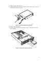
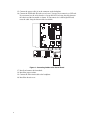
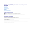
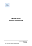
Intel® Server Chassis SR2300
Tape Drive Cable Kit
Kit Contents
The kit contains the following:
• SCSI cable with integral terminator
• Power cable
What you must purchase separately:
•
•
Intel® Server Chassis SR2300
SCSI tape drive
Installing Your Tape Drive
1. Observe all the safety precautions in your chassis’ manual.
2. Remove the tape drive from its packaging. Set any jumpers or switches according to
the manufacturer’s instructions.
3. Remove the chassis cover.
4. Disconnect the flex circuit cable from the backplane.
5. Remove the processor duct.
6. Disconnect and remove the fan module.
7. Press the blue tab toward the hot swap drives to release the tape drive carrier.
8. Remove the tape drive carrier from the chassis.
OM14657
Figure 1. Removing the Tape Drive Carrier
Order Number: A96890-001
Copyright © 2002 Intel Corporation. All rights reserved.
Intel is a registered trademark of Intel Corporation or its subsidiaries in the United States and other countries.
1
9. Remove the plastic cover from the tape drive carrier.
OM14658
Figure 2. Removing the Plastic Cover
10. Position the tape drive in the carrier and secure it with four screws.
OM14659
Figure 3. Installing the Tape Drive
2
11. Connect the power cable to the drive.
12. Connect the SCSI cable to the drive. Note that the SCSI terminator must on the end of
the SCSI cable connected to the drive.
OM14660
Figure 4. Connecting Cables to the Tape Drive
13. Feed the cables into the chassis.
14. Slide the carrier into the chassis until it latches into place. Make sure that the cables
don’t get pinched.
OM14661
Figure 5. Installing the Tape Drive Assembly
3
15. Connect the power cable (A) to the connector on the backplane.
16. Connect the SCSI cable (B) to the server board. You may also connect it to a PCI card.
If you connect it to the server board or a low profile PCI card, route the cable between
the chassis and the fan module as shown. If you connect it to a full height PCI card,
route the cable along the bottom of the fan module.
A B
OM14662
Figure 6. Connecting Cables to the Server Board
17.
18.
19.
20.
4
Install and connect the fan module.
Install the processor duct.
Connect the Flex circuit cable to the backplane.
Install the chassis cover.