1
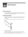
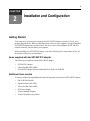
SST-64P PCI Adapter
and Subsystem
Installer/User Guide
USA Notification
Warning: Changes or modifications to this unit not expressly approved by the party responsible for compliance could void
the user’s authority to operate the equipment.
Note: This equipment has been tested and found to comply with the limits for a Class A digital device, pursuant to Part 15
of the FCC Rules. These limits are designed to provide reasonable protection against harmful interference when the equipment is operated in a commercial environment. This equipment generates, uses and can radiate radio frequency energy
and, if not installed and used in accordance with the instruction manual, may cause harmful interference to radio communications. Operation of this equipment in a residential area is likely to cause harmful interference in which case the user will
be required to correct the interference at his own expense.
Canadian Notification
This digital apparatus does not exceed the Class A limits for radio noise emissions from digital apparatus set out in the
Radio Interference Regulations of the Canadian Department of Communications.
Le présent appareil numérique n’émet pas de bruits radioélectriques dépassant les limites applicables aux appareils
numériques de la classe A prescrites dans le Règlement sur le brouillage radioélectrique édicté par le Ministère des Communications du Canada.
Safety and EMC Approvals and Markings
IEC 60950-1:2000, EN 60950-1:2001, UL 60950 3rd Ed. / CSA 22.2 No. 60950:2000,
EN 55022:1998+A1:2000+A2:2003, EN 61000-3-3:1995+A1:2001 EN 55024:1998+A1:2001+A2:2003,
FCC Part 15 Class A
SST-64P PCI Adapter
and Subsystem
Installer/User Guide
Avocent and the Avocent logo are registered trademarks of Avocent
Corporation or its affiliates. All other marks are the property of their
respective owners.
© 2006 Avocent Corporation. All rights reserved. 590-629-501A
Instructions
This symbol is intended to alert the user to the presence of important operating and maintenance
(servicing) instructions in the literature accompanying the appliance.
Dangerous Voltage
This symbol is intended to alert the user to the presence of uninsulated dangerous voltage within the
product’s enclosure that may be of sufficient magnitude to constitute a risk of electric shock to persons.
Power On
This symbol indicates the principal on/off switch is in the on position.
Power Off
This symbol indicates the principal on/off switch is in the off position.
Protective Grounding Terminal
This symbol indicates a terminal which must be connected to earth ground prior to making any other
connections to the equipment.
iii
T A B L E O F C ON T E N T S
Table of Contents
List of Figures .................................................................................................................. v
Chapter 1: Product Overview.......................................................................................... 1
Features and Benefits ........................................................................................................................ 1
The SST-64P PCI Adapter ................................................................................................................. 1
Compatibility with Prior Models ....................................................................................................... 2
Rack Mount Safety Considerations.................................................................................................... 2
Part Numbers ..................................................................................................................................... 3
Chapter 2: Installation and Configuration ..................................................................... 5
Getting Started ................................................................................................................................... 5
Items supplied with the SST-64P PCI adapter ........................................................................... 5
Additional items needed.............................................................................................................. 5
Installing the SST-64P PCI Adapter .................................................................................................. 6
Installing Port Modules ..................................................................................................................... 7
Port Module LEDs ............................................................................................................................. 7
Using rack mount ears................................................................................................................ 8
Using an HBC............................................................................................................................. 8
Using 4-foot and 1-foot HBCs .................................................................................................... 8
Using EBCs................................................................................................................................. 9
Power Options ................................................................................................................................. 10
Chapter 3: Port Module to Device Cabling .................................................................. 15
RJ-45 Connectors ............................................................................................................................ 15
Port Module Port Pinouts................................................................................................................ 15
Modular Cables ............................................................................................................................... 18
Modular Adapters ............................................................................................................................ 18
Index................................................................................................................................ 21
iv
SST-64P PCI Adapter Installer/User Manual
v
LIST OF FIGU RES
List of Figures
Figure 1.1: SST-64P PCI Adapter ..................................................................................................... 1
Figure 1.2: SST-64P PCI Adapter Compatibility .............................................................................. 2
Figure 2.1: Installing the SST-64P PCI Adapter............................................................................... 6
Figure 2.2: Port Module .................................................................................................................... 7
Figure 2.3: Port Module Mounting Options...................................................................................... 8
Figure 2.4: SST-64P PCI Adapter - Host Bus Cable - Port Module................................................. 8
Figure 2.5: SST-64P PCI Adapter with Four Port Modules Connected using HBCs....................... 9
Figure 2.6: 100 Foot (30.5 m) EBC................................................................................................... 9
Figure 2.7: Port Modules Extended Distance Using EBCs............................................................. 10
Figure 2.8: Default Power JumperSettings ..................................................................................... 11
Figure 2.9: Connected Port Modules Draw Power from Host........................................................ 12
Figure 2.10: PS-4 Supplying Power to Port Modules ..................................................................... 13
Figure 2.11: Individual PS-4s Provide Power to Port Modules Separated by EBCs ..................... 13
Figure 3.1: Port Module Connector Pinouts................................................................................... 15
Figure 3.2: RJ-45 Jack Pinouts ....................................................................................................... 16
Figure 3.3: Cable Pinouts for RJ-45 to Terminal/Printer DB-25 ................................................... 16
Figure 3.4: Cable Pinouts for RJ-45 to PC DB-9 ........................................................................... 17
Figure 3.5: Cable Pinouts for RJ-45 to Modem DB-25 .................................................................. 17
Figure 3.6: RJ-45 Modular Cable Signals ...................................................................................... 18
Figure 3.7: Ten-wire Modular Adapters Internal Wiring ............................................................... 19
vi
SST-64P PCI Adapter Installer/User Manual
1
CHAPTER
1
Product Overview
Features and Benefits
The Avocent SuperSerial Technology (SST) expandable I/O subsystem is a high-speed serial
communications multiple port product. It consists of modular components that can be configured in
a variety of combinations to satisfy most applications.
The SST-64P PCI Adapter
The SST-64P PCI adapter (see Figure 1.1) occupies one PCI slot in the host computer and provides
the intelligent communications functions to “off-load” the CPU from serial communications
processing tasks.
The SST-64P PCI adapter contains one SuperSerial Processor, which controls up to 64 ports.
Figure 1.1: SST-64P PCI Adapter
Each SST-64P PCI adapter includes software drivers and installation manuals for Microsoft
Windows, Linux and UNIX operating systems on a CD ROM. When booted, the PCI bus system
automatically identifies and configures all PCI devices connected to the system.
2
SST-64P PCI Adapter Installer/User Manual
Compatibility with Prior Models
Low profile SST-64P PCI adapters and rack-optimized port modules are compatible with the same
device drivers as prior models, and you can use them with the same cables, modular adapters and
port modules. You can also use rack-optimized port modules with prior model SST-64P adapters
and port modules. Low profile SST-64P PCI adapters may be installed together with prior model
SST PCI adapters in the same server.
Figure 1.2 illustrates compatibility among rack-optimized port modules and prior models.
SST-64P PCI Adapter
Prior Model
Port Module
Host Bus Cable
4-Feet (1.2m)
Rack-Optimized
Port Modules
PM16
INPUT
POWER
OUTPUT
OUTPUT
EXTERNAL
POWER
1
2
3
4
5
6
7
8
9
10
11
12
13
14
15
16
1
2
3
4
5
6
7
8
9
10
11
12
13
14
15
16
ONLINE
PM16
INPUT
POWER
OUTPUT
EXTERNAL
POWER
ONLINE
Figure 1.2: SST-64P PCI Adapter Compatibility
Rack Mount Safety Considerations
•
Elevated Ambient Temperature: If installed in a closed rack assembly, the operation
temperature of the rack environment may be greater than room ambient. Use care not to exceed
the rated maximum ambient temperature of the unit.
•
Reduced Airflow: Installation of the equipment in a rack should be such that the amount of
airflow required for safe operation of the equipment is not compromised.
•
Mechanical Loading: Mounting of the equipment in the rack should be such that a hazardous
condition is not achieved due to uneven mechanical loading.
•
Circuit Overloading: Consideration should be given to the connection of the equipment to the
supply circuit and the effect that overloading of circuits might have on overcurrent protection
and supply wiring. Consider equipment nameplate ratings for maximum current.
Chapter 1: Product Overview
•
3
Reliable earthing of rack mounted equipment should be maintained. Pay particular attention to
power supply connections other than direct connections to the branch circuit (for example, use
of power strips).
Part Numbers
Table 1.1 lists part numbers for the SST-64P PCI adapter, port modules, power supply, modular
adapters and cables.
Table 1.1: SST-64P PCI Adapter Part Numbers
Part Number
Description
990482
SST-64P PCI Adapter
990483
PM-16 RJ Port Module
990274-001
PS-4 Power Supply: 110V US Line Cord
990274-201
PS-4 Power Supply: 220V UK/IR Line Cord
990274-202
PS-4 Power Supply: 220V EU Line Cord
690374
Host Bus Cable, 1-foot
690277
Host Bus Cable, 4-foot
690341
Expansion Bus Cable, 10-foot
690302
Expansion Bus Cable, 25-foot
690306
Expansion Bus Cable, 100-foot
690252
10-wire Serial Cable, 10-foot
690253
10-wire Serial Cable, 25-foot
690254
10-wire Serial Cable, 75-foot
210068
DB-25 DTE Male Modular Adapter
210069
DB-25 DTE Female Modular Adapter
210070
DB-25 DCE Male Modular Adapter
210071
DB-25 DCE Female Modular Adapter
210072
DB-9 Female Modular Adapter
750080
10-wire Wiring Starter Kit
4
SST-64P PCI Adapter Installer/User Manual
5
CHAPTER
2
Installation and Configuration
Getting Started
Your computer’s host processor recognizes the SST-64P PCI adapter as memory. That is, it is a
memory mapped device. When you install the device driver on your computer, it maps all installed
SST-64P PCI adapters into system memory. The device driver soft-configures all SST-64P PCI
adapters each time you start (boot) your computer.
Before installing your SST-64P PCI adapter, refer to the following list to ensure that you have all
the items necessary for your installation.
Items supplied with the SST-64P PCI adapter
The following are supplied with the SST-64P PCI adapter:
•
SST-64P PCI Adapter
•
4-foot Host Bus Cable (HBC)
•
SST-64P PCI Adapter Drivers and Installer/User Guide on CD-ROM
Additional items needed
You may need the following additional items (sold separately) to install your SST-64P PCI adapter:
•
PM-16 RJ Port Module
•
Expansion Bus Cable (EBC)
•
1-foot Host Bus Cable (HBC)
•
PS-4 Power Supply
•
10-wire Modular Adapters
•
10-wire Serial Reversing Cables
6
SST-64P PCI Adapter Installer/User Manual
Installing the SST-64P PCI Adapter
The following procedure describes how to physically install your SST-64P PCI adapter in your
computer. Alternatively, you can follow the installation instructions provided in your host
computer documentation.
To install the SST-64P PCI adapter:
1.
Turn off the host computer and disconnect the power cord.
2.
Locate an available Peripheral Component Interconnect (PCI) slot (see Figure 2.1).
PCI Slots
Figure 2.1: Installing the SST-64P PCI Adapter
3.
Insert and secure the SST-64P PCI adapter firmly into the PCI slot.
4.
Replace the power cord and turn on your host computer.
Each SST-64P PCI adapter includes software drivers and installation manuals for Microsoft
Windows, Linux and UNIX operating systems on a CD ROM. When you start (boot) your
computer, it automatically identifies and configures all connected PCI devices. Please refer to the
serial CD ROM for device driver installation instructions.
Chapter 2: Installation and Configuration
7
Installing Port Modules
The SST-64P PCI adapter has one connector: a high-density 26-pin expansion bus port. You can
connect up to four port modules, each with sixteen RJ-45 serial ports, on the expansion bus port.
This provides the SST-64P PCI adapter a total of 64 serial ports.
The 26-pin expansion bus port is a ring topology, which contains dedicated time slots for 64 ports
of full-duplex serial data. The last port module connected to the adapter terminates the ring.
Two types of expansion bus cables are provided to connect port modules to SST-64P PCI adapters:
•
Host Bus Cables (HBCs) accomodate serial data transfers and power for the downstream port
modules. HBCs came in two sizes: 4-foot (PN 690227) and 1-foot (PN 690374).
•
Expansion Bus Cables (EBCs) accomodate only serial data transfers. When connected to an
EBC, downstream port modules require PS-4 power supplies for operational power. EBCs
come in three sizes: 10-feet (PN 690341), 25-feet (PN 690302) and 100-feet (PN 690306).
Figure 2.2 shows a port module, which contains sixteen 10-wire RJ-45 serial ports, two 26-pin
expansion bus ports (1 INPUT port for upstream connectivity and 1 OUTPUT port for downstream
connectivity). The port module also contains an external power input connector to attach the PS-4
power adapter should it require external power.
Rack Mount Ear
Expansion Bus
Input Port
Expansion Bus
Output Port
Rack Mount Ear
PM16
1
POWER
EXTERNAL
POWER
INPUT
2
3
4
5
6
7
8
9
10
11
12
13
14
15
16
OUTPUT
ONLINE
Power LED
External
Power Input
Online LED
Serial Ports
Figure 2.2: Port Module
Port modules allow you to connect serial devices to the SST-64P PCI adapter.
Port Module LEDs
Each port module contains an online LED and a power LED indicator. The online LED functions
only after you install the driver software and indicates that the port module is available for use.
The power LED lights up when power is present to the port module.
8
SST-64P PCI Adapter Installer/User Manual
Using rack mount ears
Each port module comes with two removable rack mount ears, which provide several mounting
options. Rack mount ears allow you to install port modules in a 19-inch rack, on or under a shelf or
table top, or on a wall. Figure 2.3 illustrates these various mounting options.
PM16
POWER
INPUT
EXTERNAL
POWER
1
OUTPUT
2
3
4
5
6
7
8
9
10
11
12
13
14
15
16
ONLINE
PM16
POWER
EXTERNAL
POWER
INPUT
OUTPUT
1
2
3
4
5
6
7
8
9
10
11
12
13
14
15
16
1
2
3
4
5
6
7
8
9
10
11
12
13
14
15
16
ONLINE
PM16
INPUT
POWER
OUTPUT
PM16
EXTERNAL
POWER
ONLINE
INPUT
POWER
1
OUTPUT
2
3
4
5
6
7
8
9
10
11
12
13
14
15
16
EXTERNAL
POWER
ONLINE
Figure 2.3: Port Module Mounting Options
Using an HBC
Figure 2.4 shows a basic 16-port configuration using an HBC. You can connect serial devices (such
as terminals, printers, modems, bar code readers and cash registers) to the port modules.
SST-64P PCI Adapter
HBC
Port
Module
4-Feet (1.2m)
PM16
INPUT
POWER
OUTPUT
1
2
3
4
5
6
7
8
9
10
11
12
13
14
15
16
EXTERNAL
POWER
ONLINE
Figure 2.4: SST-64P PCI Adapter - Host Bus Cable - Port Module
Using 4-foot and 1-foot HBCs
You can connect up to four port modules to the expansion bus port of the SST-64P PCI adapter
using Host Bus Cables (HBCs). First, interconnect the port modules from the OUTPUT connector
of one to the INPUT connector of the next using 1-foot HBCs. Finally, connect the INPUT
connector of the first port module to the expansion bus connector on SST-64P PCI adapter using a
4-foot HBC. This allows expansion of the entire system without disassembling the computer.
Chapter 2: Installation and Configuration
You can connect a maximum of four port modules per port bus as shown in Figure 2.5.
SST-64P PCI Adapter
Four
Connected Port
Modules
HBC
4-Feet (1.2m)
PM16
INPUT
OUTPUT
1
2
3
4
5
6
7
8
9
10
11
12
13
14
15
16
1
2
3
4
5
6
7
8
9
10
11
12
13
14
15
16
1
2
3
4
5
6
7
8
9
10
11
12
13
14
15
16
1
2
3
4
5
6
7
8
9
10
11
12
13
14
15
16
EXTERNAL
POWER
POWER
ONLINE
PM16
INPUT
OUTPUT
EXTERNAL
POWER
POWER
ONLINE
1-foot HBCs
PM16
INPUT
OUTPUT
EXTERNAL
POWER
POWER
ONLINE
PM16
INPUT
OUTPUT
EXTERNAL
POWER
POWER
ONLINE
Figure 2.5: SST-64P PCI Adapter with Four Port Modules Connected using HBCs
Using EBCs
You can place port modules farther than the supplied 4-foot (1.2m) HBC allows by replacing the
HBC with an EBC. As shown in Figure 2.6, a group of four port modules are located 100 feet
(30.5m) from the host computer using an EBC. EBCs may be used when the host computer is
located away from the wiring closet where all the peripheral cables are. When you attach port
modules to an EBC (not an HBC), it is mandatory to supply power to the port modules using the
optional power supply PS-4. For more information, see Power Options on page 10.
SST-64P PCI Adapter
EBC
Port
Modules
100 Feet (30.5m)
Maximum
PM16
INPUT
OUTPUT
1
2
3
4
5
6
7
8
9
10
11
12
13
14
15
16
1
2
3
4
5
6
7
8
9
10
11
12
13
14
15
16
EXTERNAL
POWER
POWER
ONLINE
PS-4
To AC Power Source
PM16
INPUT
POWER
OUTPUT
EXTERNAL
POWER
ONLINE
PM16
INPUT
POWER
OUTPUT
1
2
3
4
5
6
7
8
9
10
11
12
13
14
15
16
EXTERNAL
POWER
ONLINE
PM16
INPUT
POWER
OUTPUT
1
EXTERNAL
POWER
ONLINE
Figure 2.6: 100 Foot (30.5 m) EBC
2
3
4
5
6
7
8
9
10
11
12
13
14
15
16
9
10
SST-64P PCI Adapter Installer/User Manual
EBCs are available in 10-foot (3.05m) (PN 690341), 25-foot (7.6m) (PN 690302) and 100-foot
(30.5m) (PN 690306) lengths. In addition to extending the distance between the SST-64P PCI
adapter and the port modules, you can use EBCs to extend the distance between adjacent port
modules as shown in Figure 2.7. Port modules connected this way require the optional power
supply PS-4.
SST-64P PCI Adapter
EBC
Port Module
100 Feet (30.5m)
Maximum
PM16
INPUT
POWER
OUTPUT
1
2
3
4
5
6
7
8
9
10
11
12
13
14
15
16
10
11
12
13
14
15
16
EXTERNAL
POWER
ONLINE
PS-4
EBC
100 Feet (30.5m)
Maximum
To AC Power Source
Port Module
PM16
INPUT
POWER
OUTPUT
1
2
3
4
5
6
7
8
9
EXTERNAL
POWER
ONLINE
PS-4
To AC Power Source
Figure 2.7: Port Modules Extended Distance Using EBCs
NOTE: The maximum distance between the SST-64P PCI adapter and the first port module is 100 feet (30.5m).
The maximum distance between port modules is also 100 feet (30.5m).
Power Options
The SST-64P PCI adpter provides several options for sourcing power for attached port modules.
These options are configurable via jumper settings. The default power jumper setting derives power
for port modules from the PCI bus of the host computer.
NOTE: SST-64P PCI adapter power jumpers are configured to provide power to the port modules through the
host bus cable. In most situations, you do not need to reconfigure any of the power jumpers.
Chapter 2: Installation and Configuration
11
SST-64 adapter jumper settings
The default power jumper setting, shown in Figure 2.8, selects the PCI bus as the power source for
attached port modules. Refer to Table 2.1 for more jumper settings.
Power LED
9
10
1
2
HDR6
Expansion Bus Connector
9
10
1
2
HDR6
Figure 2.8: Default Power JumperSettings
12
SST-64P PCI Adapter Installer/User Manual
Table 2.1: SST-64P Adapter Power Jumper Settings
Jumper Setting
9
10
Description
1
2
Derives power from the PCI bus connector to the EBC.
1
2
Derives power from P3 (4 pin right angle plug on top edge of adapter) to
the EBC. This setting can be used to reduce load on the PCI bus when
HBCs are used to connect port modules.
1
2
To use an external power supply (PS4) for port module(s) remove all
jumpers or store them by tying pin 1 to pin 3 and pin 2 to pin 4.L LED
should be OFF.
HDR6
9
10
HDR6
9
10
HDR6
In simple configurations, the SST-64P PCI adapter supplies power to all port modules attached to
the expansion bus through the supplied 4-foot (1.2m) HBC (see Figure 2.9). The SST-64P PCI
adapter provides power through the HBC to the first port module and to the next port module
through the 1-foot HBC.
SST-64P PCI Adapter
HBC
Connected Port Modules
4-Feet (1.2m)
PM16
INPUT
POWER
OUTPUT
1
2
3
4
5
6
7
8
9
10
11
12
13
14
15
16
1
2
3
4
5
6
7
8
9
10
11
12
13
14
15
16
EXTERNAL
POWER
ONLINE
1-foot HBC
PM16
INPUT
POWER
OUTPUT
EXTERNAL
POWER
ONLINE
Figure 2.9: Connected Port Modules Draw Power from Host
NOTE: Port modules draw power from the host computer only when the port modules are connected using an
HBC cable.
Chapter 2: Installation and Configuration
13
Port modules connected to an EBC (not an HBC) must be externally powered using the PS-4
optional power supply (PN 990274). Connect the power supply (purchased separately) to the first
port module on the expansion bus (see Figure 2.10).
SST-64P PCI Adapter
EBC
Port
Modules
100 Feet (30.5m)
Maximum
PM16
INPUT
POWER
OUTPUT
1
2
3
4
5
6
7
8
9
10
11
12
13
14
15
16
1
2
3
4
5
6
7
8
9
10
11
12
13
14
15
16
EXTERNAL
POWER
ONLINE
PS-4
To AC Power Source
PM16
INPUT
POWER
OUTPUT
EXTERNAL
POWER
ONLINE
Figure 2.10: PS-4 Supplying Power to Port Modules
By connecting the PS-4 power supply to the first port module, power is no longer drawn from the
host computer. All port modules connected to one another from the first port module are supplied
power from the PS-4 power supply. The PS-4 power supply can supply power for up to four port
modules if the port modules are interconnected using 1-foot HBCs.
When you use EBCs between port modules, attach a PS-4 power supply to each module as shown
in Figure 2.11. This is required because EBC cables do not accomodate power transmission.
SST-64P PCI Adapter
EBC
Port Module
100 Feet (30.5m)
Maximum
PM16
INPUT
POWER
OUTPUT
1
2
3
4
5
6
7
8
9
10
11
12
13
14
15
16
10
11
12
13
14
15
16
EXTERNAL
POWER
ONLINE
PS-4
To AC Power Source
EBC
100 Feet (30.5m)
Maximum
Port Module
PM16
INPUT
POWER
OUTPUT
1
2
3
4
5
6
7
8
9
EXTERNAL
POWER
ONLINE
PS-4
To AC Power Source
Figure 2.11: Individual PS-4s Provide Power to Port Modules Separated by EBCs
NOTE: Do not use 4-foot HBCs between port modules. Use only 1-foot HBCs or EBCs.
14
SST-64P PCI Adapter Installer/User Manual
15
CHAPTER
3
Port Module to Device Cabling
RJ-45 Connectors
SST port modules contain 10-wire RJ-45 connectors, to which you can connect to a wide variety of
modular adapters (DB-25, DB-9, DTE and DCE) using 10-wire modular serial cables.
All serial ports provide a standard RS-232 interface with full modem control signals.
To help wire the serial ports, Avocent sells a complete set of cabling accessories. Refer to SST-64P
PCI Adapter Part Numbers on page 3.
Port Module Port Pinouts
The port module provides standard RS-232 DTE signals on all modular jacks (10-pin). Each
modular jack accomodates one serial device, see Figure 3.1.
Figure 3.1: Port Module Connector Pinouts
See Figure 3.2 for the RJ-45 jack pinouts.
16
SST-64P PCI Adapter Installer/User Manual
Figure 3.2: RJ-45 Jack Pinouts
Please note the following cabling considerations:
•
All port module jacks face toward the front with the key on the bottom. Refer to Figure 3.3,
Figure 3.4 and/or Figure 3.5 for modular jack cable pinouts.
•
You can use either twisted-pair or flat modular cable as a signal path from port modules to
peripheral devices. Twisted pair must be wired as a reversing cabling: Pin 1 to 10, pin 2 to pin
9 and so on.
Figure 3.3: Cable Pinouts for RJ-45 to Terminal/Printer DB-25
Chapter 3: Port Module to Device Cabling
Figure 3.4: Cable Pinouts for RJ-45 to PC DB-9
Figure 3.5: Cable Pinouts for RJ-45 to Modem DB-25
17
18
SST-64P PCI Adapter Installer/User Manual
Modular Cables
The following cable diagrams show how to build your own cables to go between a port module and
serial devices such as terminals, printers, PCs and modems.
RJ-45 modular cable is a flat cable often used for wiring telephones inside of buildings. The cable
is terminated at each end with an RJ-45 modular plug (connector) which is inserted into the
modular jack of an appropriate wiring module. Standard modular cables available from Avocent
are reversing. That is, the pins are reversed on each end so that pin 1 on one end is connected to pin
10 on the opposite end. Figure 3.6 shows the signals passed through modular cables when
connected to a port module serial port.
SST Serial Port
Peripheral Device
Figure 3.6: RJ-45 Modular Cable Signals
Modular Adapters
Figure 3.7 shows the internal wiring for the 10-wire modular adapters. Ten-wire modular adapters
convert modular jacks to DB-25 (RS-232) connectors. Use the information in Figure 3.7 with the
documentation provided with your host computer equipment as a guide to select the correct
modular wiring accessories.
Chapter 3: Port Module to Device Cabling
Figure 3.7: Ten-wire Modular Adapters Internal Wiring
19
20
SST-64P PCI Adapter Installer/User Manual
21
INDE X
Index
Numerics
100-foot EBC 10
10-foot EBC 10
10-wire modular adapters 18
16-port configuration 8
1-foot HBC 8
external power 7
external power input connector 7
F
flat modular cables 16
full-duplex serial data 7
25-foot EBC 10
H
4-foot HBC 9
HBC 7, 8
A
host bus cables 7
additional items 5
I
Ambient Temperature 2
INPUT connector 8
B
installation instructions 6
booting your computer 5
installation manuals 1, 6
installing port modules 7
C
installing the SST-64P PCI adapter 6
cable diagrams 18
L
cables 2
Circuit Overloading 2
Linux 1
connecting serial devices 8
M
D
Mechanical Loading 2
DB-25 (RS-232) connectors 18
dedicated time slots 7
default power jumper setting 10, 11
device drivers 2
E
EBCs 7, 10
expansion bus cables 7
expansion bus port 7, 8
Microsoft Windows 1, 6
modular adapters 2
modular jack cable pinouts 16
Mounting Options 8
mounting options 8
O
online LED indicator 7
operating systems 1, 6
OUTPUT connector 8
22
SST-64P Installer/User Guide
OUTPUT port 7
P
part numbers 3
RJ-45 modular cable 18
RJ-45 modular cable signals 18
RJ-45 modular plug 18
PCI bus 1, 10
S
PCI devices 6
Safety Considerations 2
port module 2, 7
serial communications processing 1
port module connector pinouts 15
serial data transfer 7
port module LEDs 7
serial data transfers 7
port module serial port 18
software drivers 1, 6
port modules 7, 8
SST 1
power for the downstream port modules 7
SST-64P PCI Adapter 1, 6
power jumpers 10
SST-64P PCI adapter 1, 2, 5
power LED 7
SuperSerial Proccessor 1
power LED indicator 7
SuperSerial Technology (SST) 1
power supply PS-4 10
supplied items 5
PS-4 power supplies 7
system memory 5
PS-4 power supply 10
T
R
Ten-wire modular adapters 18
Rack Mount Safety Considerations 2
ten-wire modular adapters internal wiring 19
rack-mount ears 8
twisted-pair cables 16
rack-optimized port module 2
Reduced Airflow 2
U
Reliable earthing 3
UNIX 1, 6
ring topology 7
W
RJ-45 jack pinouts 15, 16
Windows 1, 6
For Technical Support:
www.avocent.com/support
Avocent Corporation
4991 Corporate Drive
Huntsville, Alabama 35805-6201
USA
Tel: +1 256 430 4000
Fax: +1 256 430 4031
Avocent Asia Pacific
Singapore Branch Office
100 Tras Street, #15-01
Amara Corporate Tower
Singapore 079027
Tel: +656 227 3773
Fax: +656 223 9155
Avocent Canada
20 Mural Street, Unit 5
Richmond Hill, Ontario
L4B 1K3 Canada
Tel: +1 877 992 9239
Fax: +1 877 524 2985
590-629-501A
Avocent International Ltd.
Avocent House, Shannon Free Zone
Shannon, County Clare, Ireland
Tel: +353 61 715 292
Fax: +353 61 471 871
Avocent Germany
Gottlieb-Daimler-Straße 2-4
D-33803 Steinhagen
Germany
Tel: +49 5204 9134 0
Fax: +49 5204 9134 99