1
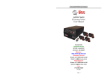
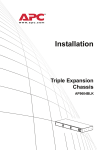
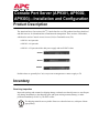
Console Port Server (AP9301, AP9302, AP9303)—Installation and Configuration Product Description The American Power Conversion (APC®) Console Port Server (CPS) product line allows both local and dial-in access for in-band and out-of-band network management. There are three CPS models, which can be used as Console Access Servers (CAS) or Terminal Servers (TS): • AP9301: An 8-port unit • AP9302: A 16-port unit • AP9303: A 32-port unit with a dual power supply and two PCMCIA slots AP9301 AP9302 AP9303 Default values are generally for CAS, but you can reconfigure these values to apply to TS. Inventory Receiving inspection Inspect the package and contents for shipping damage, and make sure that all parts were sent. Report any damage immediately to the shipping agent, and report missing contents, damage, or other problems immediately to APC or your APC reseller. The shipping materials are recyclable. Please save them for later use, or dispose of them appropriately. Note Console Port Server (AP9301, AP9302, AP9303)—Installation and Configuration: Installation Inventory Your product package should include the following: • The model of CPS that you ordered • Two brackets for mounting the CPS in an APC NetShelter® or other standard 19-inch rack or enclosure • Eight Phillips-head screws for attaching the brackets to the CPS and at the mounting location within the rack or enclosure • For AP9301 or AP9302, one power cable, or for AP9303, two power cables • DB9/RJ45 console cable • This Quick-Start Manual, printed • The Declaration of Conformity, printed • The product registration card • The APC Documentation CD, containing the following: – The User’s Guide in PDF format – The Reference Guide in PDF format – This Quick-Start Manual in PDF format Installation Pre-installation checklist You must confirm the following before installing and configuring the CPS: Linux ®/UNIX® access Windows® users You will need Kermit® or Minicom® Ensure that HyperTerminal is set up on your Windows operating system. Install the CPS 1. Mount the CPS in a 19-inch rack or enclosure using the brackets and screws provided. The CPS requires one U-space. 2. Connect a power cord (provided) to the power supply on the CPS and to an electrical outlet. For the AP9303, connect the second provided power cord to the second power supply. To help prevent electric shock, plug the CPS into a properly grounded power source. The cable is equipped with a 3-prong plug to help ensure proper grounding. Do not use adapter plugs or remove the grounding prong from the cable. If you use an extension Warning cable, use a 3-wire cable with properly grounded plugs. 2 APC Console Port Server Installation and Configuration Configuration Configure the initial settings If you have a DHCP server on your LAN. Use the Web interface to configure the initial settings for the CPS. (The CPS comes with a DHCP client enabled by default.) 1. After the DHCP server assigns an IP address to the CPS automatically, type that IP address into the address field of your Web browser. Note If the DHCP server fails to answer the automatic IP address request, the CPS will use the static IP address 192.168.160.10. If this occurs, do not continue with this procedure, but use the procedure in “If you do not have a DHCP server on your LAN.” on page 3. 2. Change the root user password. Note When setting up a CPS for the first time, always change the password of the root user as soon as possible after an IP address is assigned. Failure to change the root user password leaves your LAN vulnerable to unauthorized access of the CPS. See “Change the Root Password” on page 5. 3. Click the Network link on the top banner and click Host Setting on the left navigation menu to configure the basic parameters.You must configure the following settings: – Gateway IP: The IP address of the default gateway. – Network Mask: The subnet mask. For a detailed description of the other parameters, see “Installation and Configuration” in the User’s Guide. Note 4. To make the changes effective and save them to flash, click the apply changes button and click OK in the dialog that appears. 5. The CPS is now configured as a CAS with its assigned IP address and no authentication. You can use Telnet to connect to the CPS at serial port 1 with the following command: telnet <assigned_IP_address> 7001 If you do not have a DHCP server on your LAN. Configure the initial settings of your CPS through a serial connection to a COM port. 1. Connect the DB9/RJ45 console cable (provided) to the port labeled Console on the back of the CPS and to COM port 1 on your computer. 2. Apply power to the CPS. 3. Open a terminal emulation program such as HyperTerminal or Minicom, and configure the serial port at 9600 bps, 8 data bits, no parity, 1 stop bit, and no flow control. 4. Log on. Use the login name root and the password apc. APC Console Port Server Installation and Configuration 3 Console Port Server (AP9301, AP9302, AP9303)—Installation and Configuration: Configuration 5. Type wiz, press ENTER, and follow the on-screen instructions. You must configure the following settings: – DHCP enabled/disabled: Disable DHCP – System IP: The IP address you want to assign to the CPS – Gateway IP: The IP address of the default gateway – Network Mask: The subnet mask 6. On the confirmation screen, confirm your parameter settings. – If they are correct, type y and proceed to the next step. – If they are not correct, type n. Then type c to change any values and reconfirm them. 7. To activate your configurations, type y. To make the configuration permanent by saving it to flash, type y again when prompted. 8. Exit from the terminal emulation program. 9. Use the Web interface of the CPS to change the root user’s password. When setting up a CPS for the first time, always change the password of the root user as soon as possible after an IP address is assigned. Failure to change the root user’s password leaves your LAN vulnerable to unauthorized access of the CPS. See “Change Caution the Root Password” on page 5. 10. On the Host Settings page of the Web interface, configure any other basic parameters. For a detailed description of the parameters, see “Installation and Configuration” in the User’s Guide. 11. To make the changes effective and save them to flash, click on the apply changes button and click OK in the dialog that appears. 12. The CPS is now configured as a CAS with its assigned IP address and no authentication. You can use Telnet to connect to the CPS at serial port 1 with the following command: telnet <assigned_IP_address> 7001 4 APC Console Port Server Installation and Configuration Select a Security Profile To select a security profile 1. From the main menu, select Security, then Security Profile. Alternately, click the Wizard button and select Step 1: Security Profile. 2. Select a pre-defined security profile, or define a custom profile for specific services. – Secured: Disables all protocols except Secure SHell (SSH) v2, HyperText Transfer Protocol with Secure SHell (HTTPS), and SSH to Serial Ports. – Moderate: Enables Telnet, SSHv1, SSHv2, HTTP, HTTPS, Internet Control Message Protocol (ICMP), HTTP redirection to HTTPS, and raw connections to Serial Ports. – Open: Enables all services: Telnet, SSHv1, SSHv2, HTTP, HTTPS, Simple Network Management Protocol (SNMP), Remote Procedure Call (RPC), ICMP, and raw connections to serial ports. – Default: Sets the profile to the Moderate security profile. – Custom: Enable or disable individual protocols and services, and configure access to ports. Change the Root Password Use your Web browser to connect to the IP address of the CPS, and use the username root and the default password apc to log on to the Web interface. Then change the password of the root user, as follows: 1. Click the link Web Security > Users and Groups. 2. Select the root user, and click Change Password. 3. Type the password twice, and click Submit. 4. Click the try changes button. 5. At the Login page, type the username root and the password that was configured, then click the Login button. 6. After the authentication, click apply changes. APC Console Port Server Installation and Configuration 5 How to Interpret the LEDs The rear panel of the CPS model AP9303 has the following LEDs, connectors, and serial ports. (The AP9301 and AP9302 models do not have a P2 LED and have fewer serial ports.) Ethernet connector The Ethernet connector (labeled 10/100Base-T) has a column of three LEDs . LED Function COL Alerts you that a collision occurs on the LAN every time the unit tries to transmit an Ethernet packet. LK/DT LK (Link State): The LED is illuminated steadily if the LAN is active. DT (Data Transaction): The LED flashes when data is transmitted to or received from the LAN. This LED is hardware-controlled. 100 If 100Base-T is detected, the LED illuminates. If 10Base-T is detected, it turns off. Console connector The Console connector (labeled Console) has a column of two or three LEDs , depending on the CPS model. 6 LED Function CP Indicates Central Processing Unit (CPU) activity. It flashes at intervals of about one second. P1 Indicates power supply #1 is ON. P2 Indicates power supply #2 is ON (AP9303 only). APC Console Port Server Installation and Configuration Console Port Server (AP9301, AP9302, AP9303)—Installation and Configuration: How to Interpret the LEDs CP LED Normally the CP LED (CPU status LED) blinks consistently (one second on, one second off). Any other blinking pattern indicates an error during start-up. Event CPU LED Blinking Pattern (S=Short, L=Long) Normal Operation S (continuously) Flash Memory Error - Code L (continuously) Flash Memory Error - S, L Configuration Ethernet Error S, S, L No Interface Card Detected S, S, S, L Network Boot Error S, S, S, S, L Real-Time Clock Error S, S, S, S, S, L Note The Ethernet error listed in the preceding table will occur automatically if the Fast Ethernet link is not connected to an external hub during start-up. If the Fast Ethernet is not being used or is connected later, this error can be ignored. Serial ports To the left of the Ethernet and Console Connectors are two rows of serial ports , totaling 8, 16, or 32, depending on the CPS model. Each serial port has two LEDs. LED Function DT When illuminated, this Green LED indicates a Data Terminal Ready (DTR) signal; data is being transmitted to or received from the serial line. This is a software-controlled LED. LK When illuminated, this yellow LED indicates that the Link State (the connection to the LAN) is active. This is a hardware-controlled LED. APC Console Port Server Installation and Configuration 7 Cables and Adapters The following cables and adapters are available for purchase from APC to use with your CPS. Choose those that are appropriate for the equipment you are managing with the CPS. Cables Part Number Cable Description AP9307 DB9F to RJ45 crossover cable AP9308 DB25M to RJ45 cable AP9309 DB25F to RJ45 crossover cable AP9317 RJ45 to RJ12 CPS to Rack PDU cable Adapters 8 Part Number Adapter Description AP9310 DB25F to RJ45 crossover adapter AP9311 DB25M to RJ45 crossover adapter AP9313 DB9F to RJ45 crossover adapter AP9314 DB9M to RJ45 crossover adapter AP9315 RJ45 to RJ45 Cisco/SUN adapter AP9316 CPS Console Port to UPS DB9 adapter APC Console Port Server Installation and Configuration Two-Year Factory Warranty This warranty applies only to the products you purchase for your use in accordance with this manual. Terms of warranty APC warrants its products to be free from defects in materials and workmanship for a period of two years from the date of purchase. APC will repair or replace defective products covered by this warranty. This warranty does not apply to equipment that has been damaged by accident, negligence or misapplication or has been altered or modified in any way. Repair or replacement of a defective product or part thereof does not extend the original warranty period. Any parts furnished under this warranty may be new or factory-remanufactured. Non-transferable warranty This warranty extends only to the original purchaser who must have properly registered the product. The product may be registered at the APC Web site, www.apc.com. Exclusions APC shall not be liable under the warranty if its testing and examination disclose that the alleged defect in the product does not exist or was caused by end user’s or any third person’s misuse, negligence, improper installation or testing. Further, APC shall not be liable under the warranty for unauthorized attempts to repair or modify wrong or inadequate electrical voltage or connection, inappropriate on-site operation conditions, corrosive atmosphere, repair, installation, exposure to the elements, Acts of God, fire, theft, or installation contrary to APC recommendations or specifications or in any event if the APC serial number has been altered, defaced, or removed, or any other cause beyond the range of the intended use. THERE ARE NO WARRANTIES, EXPRESS OR IMPLIED, BY OPERATION OF LAW OR OTHERWISE, OF PRODUCTS SOLD, SERVICED OR FURNISHED UNDER THIS AGREEMENT OR IN CONNECTION HEREWITH. APC DISCLAIMS ALL IMPLIED WARRANTIES OF MERCHANTABILITY, SATISFACTION AND FITNESS FOR A PARTICULAR PURPOSE. APC EXPRESS WARRANTIES WILL NOT BE ENLARGED, DIMINISHED, OR AFFECTED BY AND NO OBLIGATION OR LIABILITY WILL ARISE OUT OF, APC RENDERING OF TECHNICAL OR OTHER ADVICE OR SERVICE IN CONNECTION WITH THE PRODUCTS. THE FOREGOING WARRANTIES AND REMEDIES ARE EXCLUSIVE AND IN LIEU OF ALL OTHER WARRANTIES AND REMEDIES. THE WARRANTIES SET FORTH ABOVE CONSTITUTE APC’S SOLE LIABILITY AND PURCHASER’S EXCLUSIVE REMEDY FOR ANY BREACH OF SUCH WARRANTIES. APC WARRANTIES EXTEND ONLY TO PURCHASER AND ARE NOT EXTENDED TO ANY THIRD PARTIES. IN NO EVENT SHALL APC, ITS OFFICERS, DIRECTORS, AFFILIATES OR EMPLOYEES BE LIABLE FOR ANY FORM OF INDIRECT, SPECIAL, CONSEQUENTIAL OR PUNITIVE DAMAGES, ARISING OUT OF THE USE, SERVICE OR INSTALLATION, OF THE PRODUCTS, WHETHER SUCH DAMAGES ARISE IN CONTRACT OR TORT, IRRESPECTIVE OF FAULT, NEGLIGENCE OR STRICT LIABILITY OR WHETHER APC HAS BEEN ADVISED IN ADVANCE OF THE POSSIBILITY OF SUCH DAMAGES. SPECIFICALLY, APC IS NOT LIABLE FOR ANY COSTS, SUCH AS LOST PROFITS OR REVENUE, LOSS OF EQUIPMENT, LOSS OF USE OF EQUIPMENT, LOSS OF SOFTWARE, LOSS OF DATA, COSTS OF SUBSTITUENTS, CLAIMS BY THIRD PARTIES, OR OTHERWISE. APC Console Port Server Installation and Configuration 9 NO SALESMAN, EMPLOYEE OR AGENT OF APC IS AUTHORIZED TO ADD TO OR VARY THE TERMS OF THIS WARRANTY. WARRANTY TERMS MAY BE MODIFIED, IF AT ALL, ONLY IN WRITING SIGNED BY AN APC OFFICER AND LEGAL DEPARTMENT. Warranty claims Customers with warranty claims issues may access the APC customer support network through the Support page of the APC Web site, www.apc.com/support. Select your country from the country selection pull-down menu at the top of the Web page. Select the Support tab to obtain contact information for customer support in your region. 10 APC Console Port Server Installation and Configuration ® APC Worldwide Customer Support Customer support for this or any other APC product is available at no charge in any of the following ways: • Visit the APC Web site to access documents in the APC Knowledge Base and to submit customer support requests. – www.apc.com (Corporate Headquarters) Connect to localized APC Web sites for specific countries, each of which provides customer support information. – www.apc.com/support/ Global support searching APC Knowledge Base and using e-support. • Contact an APC Customer Support center by telephone or e-mail. – Regional centers Direct InfraStruXure Customer Support Line (1)(877)537-0607 (toll free) APC headquarters U.S., (1)(800)800-4272 Canada (toll free) Latin America (1)(401)789-5735 (USA) Europe, Middle East, Africa (353)(91)702000 (Ireland) Japan (0) 35434-2021 Australia, New Zealand, (61) (2) 9955 9366 South Pacific area (Australia) – Local, country-specific centers: go to www.apc.com/support/contact for contact information. Contact the APC representative or other distributor from whom you purchased your APC product for information on how to obtain local customer support. Entire contents copyright 2006 American Power Conversion Corporation. All rights reserved. Reproduction in whole or in part without permission is prohibited. APC, the APC logo, InfraStruXure, and NetShelter are trademarks of American Power Conversion Corporation. All other trademarks, product names, and corporate names are the property of their respective owners and are used for informational purposes only. 990-1477B-001 *990-1477B-001* 12/2006