1
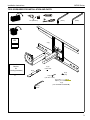
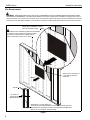
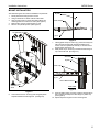
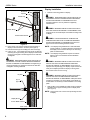
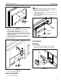
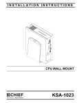
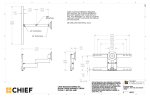
INSTALLATION INSTRUCTIONS
Instrucciones de instalación
Installationsanleitung
Instruções de Instalação
Istruzioni di installazione
Installatie-instructies
Instructions d´installation
Medium Flat Panel Steel Stud Wall Mount
Spanish Product Description
German Product Description
Portuguese Product Description
Italian Product Description
Dutch Product Description
French Product Description
JWDSK Series
JWDSK Series
Installation Instructions
DISCLAIMER
Milestone AV Technologies, Inc., and its affiliated corporations
and subsidiaries (collectively, "Milestone"), intend to make this
manual accurate and complete. However, Milestone makes no
claim that the information contained herein covers all details,
conditions or variations, nor does it provide for every possible
contingency in connection with the installation or use of this
product. The information contained in this document is subject
to change without notice or obligation of any kind. Milestone
makes no representation of warranty, expressed or implied,
regarding the information contained herein. Milestone assumes
no responsibility for accuracy, completeness or sufficiency of
the information contained in this document.
Chief® and Centris™ are trademarks of Milestone AV
Technologies, Inc. All rights reserved.
IMPORTANT WARNINGS AND
CAUTIONS!
WARNING: A WARNING alerts you to the possibility of
serious injury or death if you do not follow the instructions.
CAUTION: A CAUTION alerts you to the possibility of
damage or destruction of equipment if you do not follow the
corresponding instructions.
WARNING: Failure to read, thoroughly understand, and
follow all instructions can result in serious personal injury,
damage to equipment, or voiding of factory warranty! It is the
installer’s responsibility to make sure all components are
properly assembled and installed using the instructions
provided.
WARNING: Failure to provide adequate structural strength
for the installation of this kit can result in serious personal
injury or damage to equipment! It is the installer’s
responsibility to make sure the structure to which this kit is
attached can support five times the combined weight of all
equipment.
WARNING: Exceeding the weight capacity can result in
serious personal injury or damage to equipment! It is the
installer’s responsibility to make sure the combined weight of
all components attached to this accessory does not exceed
75 lbs (34.01 kg).
LEGEND
2
Tighten Fastener
Hex-Head Wrench
Apretar elemento de fijación
Llave de cabeza hexagonal
Befestigungsteil festziehen
Sechskantschlüssel
Apertar fixador
Chave de cabeça sextavada
Serrare il fissaggio
Chiave esagonale
Bevestiging vastdraaien
Zeskantsleutel
Serrez les fixations
Clé à tête hexagonale
Loosen Fastener
Phillips Screwdriver
Aflojar elemento de fijación
Destornillador Phillips
Befestigungsteil lösen
Kreuzschlitzschraubendreher
Desapertar fixador
Chave de fendas Phillips
Allentare il fissaggio
Cacciavite a stella
Bevestiging losdraaien
Kruiskopschroevendraaier
Desserrez les fixations
Tournevis à pointe cruciforme
Installation Instructions
JWDSK Series
TOOLS REQUIRED FOR INSTALLATION AND PARTS
1/2" (Ø13mm)
(3/16")
(5/32")
I/M
A (1)
x1
Interface
Bracket
Kit
(Including Hardware)
C (4)
8-32 x 3/8"
B (2)
x1
E (4)
(1/4")
D (4)
(1/4"-20 x 1-3/4")
TOGGLERĂ
F (4)
(1/4"-20 SNAP TOGGLE BB)
G (1)
3/16"
3
JWDSK Series
Installation Instructions
Site Requirements
WARNING: IMPROPER INSTALLATION CAN LEAD TO EQUIPMENT FALLING CAUSING SERIOUS PERSONAL INJURY
OR DAMAGE TO EQUIPMENT! The figure below identifies the minimum requirements for installation of display mounts onto a
steel stud structure. If the structure or its components do not meet these requirements contact the mount manufacturer for specific
instructions before attempting installation. It should also be noted that no other equipment should be mounted to the same stud.
16" or 24" (on center) Studs
Display Mount Installation Location
(Must be centered on stud)
If back side of wall is unfinished, drywall must be installed
to a minimum of one stud left and right of the stud(s)
being used to install the mount. Drywall must be
secured to studs with screws 12" on center
There must be a minimum of
1-7/8" (48mm) clearance
inside wall
FRONT
Drywall
1/2" minimum
Drywall Thickness
(Both Sides of Stud)
Steel Stud (2 x 4 / 25ga minimum)
Stud type and structural strength must conform to the North American
Specification for the Design of Cold-Formed Steel Structural Members.
[362 S 125 18, C-Shaped, S-Stud Section]
Figure 1
4
Installation Instructions
JWDSK Series
MOUNT INSTALLATION
After determining the site meets the installation requirements:
1.
2.
3.
4.
5.
Drywall
Identify desired mounting location on wall.
Using a stud finder or similar method locate studs.
Align mounting holes in mount with studs making sure
mounting holes are centered on studs. (See Figure 2)
Mark location of three mounting holes on wall.
Drill four 1/2" (Ø13mm) holes. (See Figure 2)
Plastic Straps
1/2" (Ø13mm) x4
(F) x4
Figure 3
7.
8.
Holding plastic straps on anchor (F), pull anchor away from
wall until channel rests flush behind wall making sure
anchor channel is positioned vertically on stud as show in
figures below. (See Figure 4)
Slide plastic cap on anchor (F) towards wall until flange of
cap is flush with wall. (See Figure 4)
Steel Stud
(A) x1
Drywall
Plastic Cap
(F) x4
Anchor Metal Channel
Mounting holes
centered on
studs
SIDE VIEW
Figure 2
6. Hold metal channel on anchor (F) flat alongside plastic
straps and slide channel through hole. (See Figure 3)
Figure 4
9.
Snap off plastic straps on anchor at wall by pushing side to
side, snapping off straps level with flange of plastic cap.
(See Figure 5)
10. Repeat steps 6 through 9 for each mounting hole.
5
JWDSK Series
Installation Instructions
Steel Stud
Drywall
Display Installation
1.
Plastic Cap
Determine mounting pattern on display.
WARNING: IMPROPER INSTALLATION CAN LEAD TO
EQUIPMENT FALLING CAUSING SERIOUS PERSONAL
INJURY AND DAMAGE TO EQUIPMENT! DO NOT
substitute hardware. Use only hardware supplied by
manufacturer!
WARNING: IMPROPER INSTALLATION CAN LEAD TO
Plastic Straps
ELECTRIC SHOCK OR DAMAGE TO EQUIPMENT! Screw
length must not exceed the depth of threaded mounting insert
in display.
Anchor Metal Channel
WARNING: OVERTIGHTENING OF SCREWS CAN
DAMAGE PARTS AND LEAD TO SERIOUS PERSONAL
INJURY AND DAMAGE TO EQUIPMENT! DO NOT over
tighten screws when installing interface bracket.
SIDE VIEW
Figure 5
11. Place mount over anchors and align mounting holes in
display mount with holes in anchors. (See Figure 6)
12. Place flat washer (E) onto Phillips pan head screws (D).
13. Insert 1/4-20 x 1-3/4" Phillips pan head screw (D) with flat
washer (E) through mounting hole in display mount and into
anchor (F) and tighten until flush against mount. DO NOT
overtighten!
NOTE: If the display being installed has a 100x100 VESA
mounting pattern, no interface bracket is required and
the display can be mounted directly to the mounting
plate as outlined below.
NOTE: If the display being installed requires an interface
bracket, refer to the interface bracket installation
instructions.
WARNING: IMPROPER INSTALLATION CAN LEAD TO
EQUIPMENT FALLING CAUSING SERIOUS PERSONAL
INJURY OR DAMAGE TO EQUIPMENT! Overtightening of
mounting hardware can damage the steel studs. DO NOT
overtighten mounting hardware!
WARNING: IMPROPER INSTALLATION CAN LEAD TO
DISPLAY FALLING CAUSING SERIOUS PERSONAL
INJURY OR DAMAGE TO EQUIPMENT! Using screws of
improper size may damage your display! Proper screws will
easily and completely thread into display mounting holes.
Ensure that screws are not too long.
Steel Stud
Drywall
WARNING: IMPROPER INSTALLATION CAN LEAD TO
DISPLAY FALLING CAUSING SERIOUS PERSONAL
INJURY OR DAMAGE TO EQUIPMENT! Inadequate thread
engagement in display may cause display to fall! Back out
screws ONLY as necessary to allow installation of mounting
plate!
(E) x 4
(D) x 4
1.
Start two M4 x 12mm Phillips pan head screws (included in
hardware kit) into upper mounting holes in display back.
(See Figure 7)
NOTE: Leave at least 1/8" of each screw protruding out back
of display.
Display Mount
Anchor Metal Channel
SIDE VIEW
Figure 6
6
Installation Instructions
JWDSK Series
CAUTION: Ensure that adequate cable slack exists for
movement of display, and that cables will not be pinched by
installation of cover (B) or screws (C).
2.
3.
1
Carefully insert cables in cavity located in lower portion of
mount arm (See Figure 9).
Using Phillips screwdriver, install cover (B) with two screws
(C). (See Figure 9)
x2
Cable Path
(typical)
Figure 7
2.
3.
4.
5.
Align two screws in display back with upper teardrop
mounting holes in mounting plate.
Place two screws in display back into upper teardrop
mounting holes in display mounting plate and lower display
until screws are seated in lower area of teardrop mounting
holes. (See Figure 8)
Install two screws through display mounting plate and into
lower mounting holes in display back. (See Figure 8)
Tighten all hardware.
(B) x 2
(C) x 4
Figure 9
ADJUSTMENTS
Swing Arm
PIVOT / SWING
1.
2
Using 3/16" hex key (G), slightly loosen or tighten the
adjustment screw(s) as necessary. (See Figure 10)
3
Adjustment Screws
4
x2
Figure 10
Figure 8
6.
Route cables and wires to display.
CABLE MANAGEMENT
1.
Attach all cables to display.
7
JWDSK Series
Installation Instructions
Adjust display Roll, Pitch, and YAW tension
1.
2.
3.
4.
5.
6.
Disconnect all wires and cable from the display.
Remove two Lower screws securing display to Centris cup.
Loosen two Upper screws securing display.
Lift display upward and away from mount.
Using a hex head wrench turn the tension adjustment screw
clockwise to increase tension, or counter-clockwise to
decrease tension. (See Figure 11)
Re-install display.
Figure 11
8
Installation Instructions
JWDSK Series
9
JWDSK Series
10
Installation Instructions
Installation Instructions
JWDSK Series
11
JWDSK Series
Installation Instructions
USA/International
Chief Manufacturing, a division of
Milestone AV Technologies, Inc.
Europe
Asia Pacific
8832-000220 RevC
©2008 Milestone AV Technologies
www.chiefmfg.com
06/08
A
P
F
A
P
F
A
8401 Eagle Creek Parkway, Savage, MN 55378
800.582.6480 / 952.894.6280
877.894.6918 / 952.894.6918
Fellenoord 130 5611 ZB EINDHOVEN, The Netherlands
+31 (0)40 2668620
+31 (0)40 2668615
Room 24F, Block D, Lily YinDu International Building
LuoGang, BuJi Town, Shenzhen, CHINA.
P +86-755-8996 9226
F +86-755-8996 9217