1
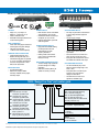
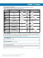
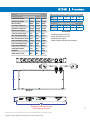
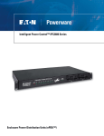
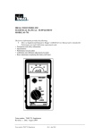
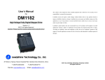
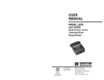
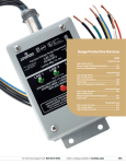
Automatic Transfer Switches T2235 Series
Enclosure Power Distribution Units (ePDU™)
Switches out of Phase Power sources. Optional power Filtering and Circuit Breaker
A2 - Version Back
T2235-AB Front
AB - Version
ONLY
PHYSICAL
• Height 1.72” (1U) x Depth 7.0”
Depth 9.5” - Versions C2, F3, F4
• Powder coated black steel
• Detachable mounting brackets allow for
several mounting options
DUAL POWER INPUT
• Power cables with plugs are attached to
unit through the rear panel cable grip
• -AB version has C20 inlets
• Cables must be ordered separately
OVERLOAD CIRCUIT PROTECTION
• (Optional) Electromagnetic circuit
breakers with long time delay curve
• Circuit breaker trip guards are provided
• C1, C2, F3, F4 require circuit breakers
for branch circuit protection to meet
NEC and UL requirements
INDICATOR LIGHTS
• (5) LED Indicator lights:
• Main Power, Primary Available,
Secondary Available, Primary Output,
Secondary Output
AB - Version Back
POWER OUTLETS
• North American versions have NEMA
style receptacles, (8) on the rear
• International versions have IEC style
receptacles, (6-12) on the rear
• Optional cable restraint system with
cable management.
POWER FILTERING (Optional)
• High performance EMI/RFI filtering
provides protection from both
electromagnetic and radio
frequency interference
• Filtering is both Common Mode
(Line to Ground) and Differential
Mode (Line to Line)
SPIKE/SURGE SUPPRESSION (TVSS)
• Transient voltage surge suppression
prevents damage due to voltage
fluctuations
• Metal Oxide Varistors (MOVs) are
utilized Line to Line (or neutral)
AUTO TRANSFER SWITCH
• Firm drop out points allow a transfer before
an under-voltage will affect equipment
operation
• Transfer ranges (Voltage):
Nominal
Drop Out
Pull In
120V
90V
103V
208V
182V
195V
240V
197V
210V
• Sources do NOT need to be phase
synchronized
• Source transfer time of less than 30ms
(clean sine wave to clean sine wave)
• Front panel LED’s indicate which sources
are available and selected at the output
VOLTAGE RANGE SELECTION
• The “AB” International (IEC) version
allows for all three voltage ranges 120V,
208V, or 240V
• Front panel switch to set the drop out
and pull in range to the desired
voltages see chart above
• This allows this one version to be
specified for worldwide usage
T2235 “Design Your Own” part number guide
T2235 -
-
B
Option 1
A1 = 120V/15A input, 12A output
Receptacles: (8) NEMA 5-15R
A2 = 120V/20A input, 16A output
Receptacles: (8) NEMA 5-20R
AB = 100-240V/20A input, 16A output
Output: (8) IEC C13 (1) IEC C19
C1 = 120V/30A input, 24A output
Receptacles: (8) NEMA 5-15R
C2 = 120V/30A input, 24A output
Receptacles: (8) NEMA 5-20R
F3 = 200-240V/30A input, 24A output
Output: (12) IEC C13
F4 = 200-240V/30A input, 24A output
Output: (4) IEC C13 (2) IEC C19
Option 5
09S = 9’ cable with straight blade plug
09L = 9’ cable with locking plug
15S = 15’ cable with straight blade plug
15L = 15’ cable with locking plug
C20 = IEC C20 power inlet, cables ordered
separately, AB version only
Option 4
B = Color Black - Adjustable Mounting
Option 3
F = Filtering
N = No Filtering
Option 2
C = Circuit Breaker
N = No Circuit Breaker
www.pulizzi.com • [email protected] • 800-870-2248 • Fax: 605-334-4999
© 2008 Eaton Corporation. All Rights Reserved. All specifications are subject to change without notice.
2
Option 1: Voltage and Current Configuration
The following chart shows the available input/output voltage and current configurations. Most options have a choice of
straight blade or twist lock connectors. This selection is made in options 3 and 4.
T2235 Series
Version
A1
A2
AB
C1
Voltage/Current
Input/Output Rating
Input Connectors
Straight Blade
Twist Lock
Output Connectors
Straight Blade
120V, 12A
120V, 16A
NA
100-240V, 16A
120V, 24A
(1) 2 Pole 15A UL listed CB
is required for branch protection
NA
C2
120V, 24A
(1) 2 Pole 20A UL listed CB
is required for branch protection
NA
F3
200-240V, 24A
(2) 2 Pole 15A UL Listed CB
is required for branch protection
NA
F4
200-240V, 24A
(2) 2 Pole 15A UL Listed CB
is required for branch protection
NA
Option 2: Circuit Breaker
This unit is available with or without a circuit breaker. The circuit breaker provides supplementary overload protection to the devices connected to the
T2235. For mission critical applications, the T2235 can be ordered without a circuit breaker, preventing a single point of failure. Select “C” in this option to
include the circuit breaker or “N” to not include it. (Circuit breakers are mandatory in C1, C2, F3, F4 versions.)
Option 3: EMI/RFI Filtering
Select “F” for filtering and “N” for no filtering.
Option 4: Color and Mounting
Powder Coat Black finish with adjustable mounting options.
Option 5: Power Cable and Plug Type
Choose either straight blade or twist lock style plug. See the table in Option 1 for a view of the available plug styles. Verify you have the correct type of
mating receptacle available at your facility. Plug types sometimes limit the available voltage and current options. The AB version is available only with
the C20 power inlet. The power cables for this version must be ordered separately.
3
www.pulizzi.com • [email protected] • 800-870-2248 • Fax: 605-334-4999
© 2008 Eaton Corporation. All Rights Reserved. All specifications are subject to change without notice.
Accessories
Optional Cable Restraint and Management
TRANSVERSE MOUNTING
KIT-CABLRES-01
• Prevent downtime and accidental disconnection
• Secure cables/plugs to Power Distribution Unit
• Cable ties provide highest level of retention
Adjustable Mounting Options
010-9334:
C19 to NEMA 5-15P
125V, 15A Straight Blade
8 foot, 14AWG/3wire
Center Mount
Mounting Brackets
Are Detachable With
Several Mounting
Options Shown
Front Flush
010-9335:
C19 to NEMA 5-20P
125V, 20A Straight Blade
8 foot, 12AWG/3wire
010-9339:
C19 to NEMA L5-20P
125V, 20A Twist-Lock
8 foot, 12AWG/3wire
Rear Flush
Front Recessed
Optional
Zero-U
Bracket
(001-1928-1)
010-9341:
C19 to NEMA L6-20P
250V, 20A Twist-Lock
8 foot, 12AWG/3wire
Rack Mounting Hole Specification Table
19.00”
010-9343:
CEE7-7 to C19
250V, 16A EUROPE (Schuko)
2.5M, 1.5mm/3wire Harmonized
Y
Z A
HOLE SPECIFICATION TABLE
A
1.75
Y
.25
Z
1.25
010-0025: 8 foot
C13 to C14 Harmonized, 1mm/3wire
100-240V rated
www.pulizzi.com • [email protected] • 800-870-2248 • Fax: 605-334-4999
© 2008 Eaton Corporation. All Rights Reserved. All specifications are subject to change without notice.
4
TVSS (Transient Voltage Surge Suppression)
MOV SPECIFICATIONS
EMI/RFI FILTERING COMMON MODE INSERTION LOSS
Mhz.
.2
1.0
2.0
10.0
dB.
15
25
45
50
Continuous AC Voltage
150VAC
270VAC
320VAC
Continuous DC Voltage
200VDC
360VDC
420VDC
Max. DC Leakage
200µA
200µA
200µA
Low Varistor Voltage Limit
212VDC
389VDC
462VDC
Mhz.
.2
1.0
2.0
10.0
High Varistor Voltage Limit
243VDC
453VDC
540VDC
dB.
10
22
32
50
Nominal Varistor Voltage
236VDC
424VDC
503VDC
Current For Varistor Voltage
1mA
1mA
1mA
Max. Clamp Voltage 8x20µs
360V
680V
810V
Max. Clamp Voltage Test Current 100A
100A
100A
Peak Current Rating (1 Pulse)
12000A
10000A
10000A
Peak Current Rating (2 Pulse)
9000A
6500A
6500A
Energy Rating (10x1000µs)
170J
325J
385J
Energy Rating (8x20µs)
170J
325J
385J
Capacitance
1700pF
970pF
820pF
Impulse Response Time
50ns
50ns
50ns
DIFFERENTIAL INSERTION LOSS
Environmental
Operating Temperature is 0 to 50 C
Storage Temperature is -40 to 70 C
Altitude Maximum 10,000 ft.
Relative Humidity is 95% Max Non-Condensing
Drawings are not shown to scale
Dimensions are in inches
www.pulizzi.com • [email protected] • 800-870-2248 • Fax: 605-334-4999
© 2008 Eaton Corporation. All Rights Reserved. All specifications are subject to change without notice.
5