1
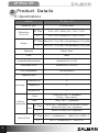
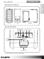
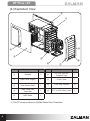
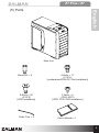
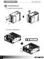
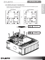
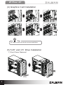
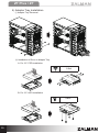
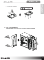
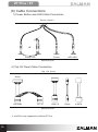
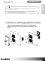
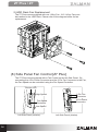
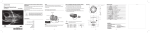
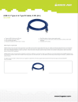
English
Z7 Plus / Z7
1) Please read this manual thoroughly prior to installation.
2) Before installation, check the components and condition of the
product. If any problem is found, contact the retailer.
English
1 Cautionary Notes
3) Avoid inserting objects or hands into the system while it is in operation
to prevent product damage and injuries.
4) Check the manual when connecting cables. Incorrect connections
may cause short circuits leading to fire hazards.
5) Do not block the Front Intake Vent or the Rear Exhaust Vent.
6) Keep this unit away from heat sources, direct sunlight, water, oil, and
humid environments, and place the unit on a flat, stable, vibration-free,
and well-ventilated area.
7) Do not clean the product surface with chemicals or wet cloth.
(chemicals: industrial brightener, wax, benzene, alcohol, paint thinner,
mosquito repellent, aromatics, lubricant, detergent etc.)
8) Please wear gloves while handling this product to prevent injuries.
9) Product design and specifications may be revised to improve quality
and performance.
The diagrams used in this manual’s installation guide are based on
the model Z7 Plus. Installation for the Z7 follows exactly the same
installation procedure.
1
Z7 Plus / Z7
2 Product Details
(1) Specifications
Models
Z7 Plus / Z7
Enclosure Type
ATX Mid Tower
Dimensions
(W×H×D)
224 × 472 × 496㎜ (8.8 × 18.6 × 19.5”)
Z7
207 × 472 × 496㎜ (8.1 × 18.6 × 19.5”)
Z7 Plus Main Unit: 7.7㎏(17lb) / with packaging: 8.7㎏(19lb)
Weight
Z7
Main Unit: 7.2㎏(16lb) / with packaging: 8.2㎏(18lb)
Materials
Plastic, Steel
Color
Black
Compatible Motherboards
Standard ATX / m-ATX
Compatible PSUs
Standard ATX / ATX12V
VGA Compatibility
Full Size(300㎜)
Expansion Slot
7
Drive Bay
External 5.25”
4
Internal 3.5“
5
External 3.5”
1
Front
120㎜ LED Fan × 1 (standard)
(120㎜ / 140㎜ option)
Rear
120㎜ Fan × 1 (standard)
Cooling
Component
Side
Front I/O Port
2
Z7 Plus
Z7 Plus
120㎜ Fan × 1(standard), Fan Control Function,
80/92/120/140㎜ Fan×1(optional)
Z7
80/92/120/140㎜ Fan×2(optional)
Z7 Plus
Mic×1, Headphones×1, USB 2.0×2, e-SATA×1
Z7
Mic×1, Headphones×1, USB 2.0×2
Z7 Plus / Z7
Front
English
(2) External Features
Top
Side(left)
(3) Top I/O Ports
Headphones
Mic
e-SATA Reset
USB 2.0
Power
Button
HDD LED
Power LED
※ The Z7 does not have an e-SATA port.
3
Z7 Plus / Z7
(4) Exploded View
②
①
⑧
④
③
⑤
⑨
⑥
⑦
#
Components
Units
#
Components
Units
①
Chassis
1
⑥
3.5”/2.5” to 5.25”
Adaptor Tray
1
②
Side Panel (Right)
1
⑦
Front Cover
1
③
Side Panel (Left)
1
⑧
5.25” Bay Covers
8
④
Side Panel Fan
Controller
1
⑨
3.5” to 5.25” Bay Cover
1
⑤
HDD Rack
1
※ The Z7 does not have a ④Side Panel Fan Controller.
4
Z7 Plus / Z7
English
(5) Parts
Main Unit
Stand-Off × 9
B Bolts × 20
(6-32*8)
[HDD Installation]
Cable Ties × 5
A Bolts × 17
(6-32*6)
[motherboard/PSU/PCI Slot Installation]
C Bolts × 6
(PWH M3*5)
[ODD, FDD, SSD Installation]
User’s Manual ×1
5
Z7 Plus / Z7
3 Installation
(1) Side Panel Removal
(2) PSU Installation
A Bolt
6
Z7 Plus / Z7
Please refer to the diagrams below to determine Stand Off installation points
before installing the motherboard.
ATX Board
m-ATX Board
English
(3) Motherboard Installation
or
Stand-Off
A Bolt
7
Z7 Plus / Z7
(4) Graphics Card Installation
Click
Tip
▶ The PCI Slot can also be secured with Bolts.
(5) 5.25” and 3.5” Drive Installation
1) Front Cover Removal
PULL
8
Z7 Plus / Z7
English
2) ODD Installation
3) 3.5” Drive Installation
① HDD Rack Removal
② 3.5” HDD Installation
B Bolt
D
D
H
9
Z7 Plus / Z7
4) Adaptor Tray Installation
① Adaptor Tray Removal
② Installation of Drive to Adaptor Tray
A. For 3.5” FDD Installation
C Bolt
5”
3.
D
D
”F
5
3.
D
FD
B. For 3.5” HDD Installation
A Bolt
3.
D
D
D
D
H
H
5”
5”
3.
10
Z7 Plus / Z7
C Bolt
D
D
SS
SS
English
C. For 2.5” SSD Installation
5) Front Cover Installation
Please remove the Front Cover’s Bay Cover before installing to the case.
11
Z7 Plus / Z7
(6) Cable Connections
1) Power Button and LED Cable Connection
Power Button
or
Power
Power LED
HDD LED
Motherboard
2) Top I/O Panel Cable Connection
Top I/O Ports
Audio
HD Audio
AC ’97
USB 2.0
Motherboard
※ e-SATA is only supported by Model Z7 Plus.
12
Reset
e-SATA
Z7 Plus / Z7
▶ For USB 2.0, e-SATA (Z7 Plus) and audio cables, please refer to the
motherboard’s manual.
▶ In the event that the Power LED/HDD LED connector’s polarities(+/-) are
reversed, the LED will not function properly.
English
Tip
(7) Additional Fan Installation and Replacement (optional)
1) Side Panel Fan Installation (80/92/120/140㎜ Fans Compatible)
The Z7 Plus comes equipped with one 120㎜ Fan. For additional fan
installation, remove the Fan Cover(left) and install the fan(right) as shown
below.
13
Z7 Plus / Z7
2) HDD Rack Fan Replacement
The Z7 Plus comes equipped with one 120㎜ Fan. 120 / 140㎜ Fans can
be installed to the HDD Rack. Please refer to the diagram below for fan
replacement.
(8) Side Panel Fan Control [Z7 Plus]
The Z7 Plus comes equipped with a Fan Control on the left Side Panel. By
connecting the 4-Pin Power Connector and the 3-Pin Fan Connector to the Fan,
the Fan Speed can be controlled using the Fan Speed Controller.
Activity LED
High Speed
Fan Speed
Controller
3-Pin Fan
Connector
4-Pin Power
Connector
Low Speed
Left Side Panel (exterior)
14
Left Side Panel (interior)
Z7 Plus / Z7
English
MEMO
15