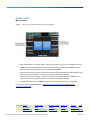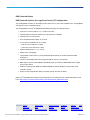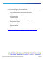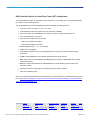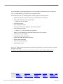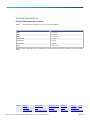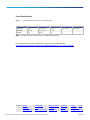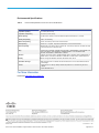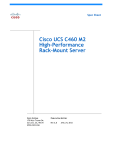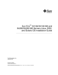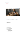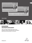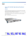
1
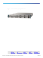
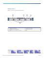
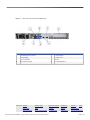
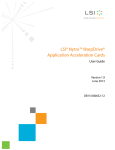
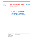
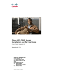
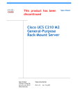
SpecSheet
Cisco UCS C200 M2 High-Density Rack-Mount
Server
Overview
®
The Cisco UCS C200 M2 High-Density Rack-Mount Server is a high-density, two-socket, one rack-unit (1RU)
™
rack-mount server that extends the capabilities of the Cisco Unified Computing System , using Intel’s latest Xeon
5600 Series multi-core processors with 12 DIMM slots, and two PCIe slots.
The UCS C200 M2 server is available in two versions: one with eight (8) 2.5-inch small form factor (SFF) hard disk
drives or solid-state drives and one with four (4) 3.5-inch large form factor (LFF) hard drives offering added
flexibility for a right-sized solution.
Figure 1.
Cisco UCS C200 M2 LFF High-Density Rack-Mount Server
Contents: Overview
Detailed Views
Base Unit Features
Configuring
Memory
Option Cards
RAID
Software
Services
Memory Notes
Option Card Notes
RAID Controller Notes
Physical Specs
Power Specs
Environmental Specs
© 2011 Cisco and/or its affiliates. All rights reserved. This document is Cisco Public Information.
HDD
Page 1 of 33
Figure 2.
Cisco UCS C200 M2 SFF High-Density Rack-Mount Server
Contents: Overview
Detailed Views
Base Unit Features
Configuring
Memory
Option Cards
RAID
Software
Services
Memory Notes
Option Card Notes
RAID Controller Notes
Physical Specs
Power Specs
Environmental Specs
© 2011 Cisco and/or its affiliates. All rights reserved. This document is Cisco Public Information.
HDD
Page 2 of 33
Detailed Views
Figure 3.
Front View of the Cisco UCS C200 M2 LFF Server
Front Panel Features
A
Slim-line 24x SATA DVD-RW
D
System Status LED Panel
B
4 x SAS/SATA 3.5 inch Hard Disk Drive
E
Operator Indicator Panel
C
Keyboard, video, monitor, (KVM) Console Connector
Contents: Overview
Detailed Views
Base Unit Features
Configuring
Memory
Option Cards
RAID
Software
Services
Memory Notes
Option Card Notes
RAID Controller Notes
Physical Specs
Power Specs
Environmental Specs
© 2011 Cisco and/or its affiliates. All rights reserved. This document is Cisco Public Information.
HDD
Page 3 of 33
Figure 4.
Front View of the Cisco UCS C200 M2 SFF Server
Front Panel Features
A
System Status LED Panel
B
Optional Slim-line 24x SATA DVD-RW
Contents: Overview
C
8 x SAS/SATA or SSD 2.5 inch Hard Disk Drive
Detailed Views
Base Unit Features
Configuring
Memory
Option Cards
RAID
Software
Services
Memory Notes
Option Card Notes
RAID Controller Notes
Physical Specs
Power Specs
Environmental Specs
© 2011 Cisco and/or its affiliates. All rights reserved. This document is Cisco Public Information.
HDD
Page 4 of 33
Figure 5.
Note:
Detailed View of the Operator Panel on the Cisco UCS C200 M2 Server
The Operator Panel replaces the Optional DVD Panel Module on the Cisco UCS C200 M2 SFF Server.
When the DVD Module Panel is selected for the UCS C200 M2 SFF server, the front KVM Console Connector is
not available.
Contents: Overview
Detailed Views
Base Unit Features
Configuring
Memory
Option Cards
RAID
Software
Services
Memory Notes
Option Card Notes
RAID Controller Notes
Physical Specs
Power Specs
Environmental Specs
© 2011 Cisco and/or its affiliates. All rights reserved. This document is Cisco Public Information.
HDD
Page 5 of 33
Figure 6.
KVM Console Connector on the Cisco UCS C200 M2 Server
Contents: Overview
Detailed Views
Base Unit Features
Configuring
Memory
Option Cards
RAID
Software
Services
Memory Notes
Option Card Notes
RAID Controller Notes
Physical Specs
Power Specs
Environmental Specs
© 2011 Cisco and/or its affiliates. All rights reserved. This document is Cisco Public Information.
HDD
Page 6 of 33
Figure 7.
Rear View of the Cisco UCS C200 M2 Server
Rear Panel Features
A
10/100 Management Port (RJ-45)
E
2 x Power Supplies
B
Serial Port (DB9)
F
2 x USB 2.0 Ports
C
PCIe Low-Profile Slot
G
VGA Port
D
PCIe Standard Profile Slot
H
2 x 1GbE (1000BASE-T)
Contents: Overview
Detailed Views
Base Unit Features
Configuring
Memory
Option Cards
RAID
Software
Services
Memory Notes
Option Card Notes
RAID Controller Notes
Physical Specs
Power Specs
Environmental Specs
© 2011 Cisco and/or its affiliates. All rights reserved. This document is Cisco Public Information.
HDD
Page 7 of 33
Base Unit Features
Table 1.
Feature Specifications for the Cisco UCS C200 M2 Server
Feature
Specification
CPU
Up to two Intel Xeon 5500 or 5600 Series processors
®
®
®
Chipset
Intel 5520 (Tylersburg) chipset
Memory
12 DIMM slots (up to 192 GB)
NIC
Embedded dual-port Intel 82576NS PCIe-based Gigabit Ethernet controller
Expansion Slots
2 PCIe slots (see PCIe Slot Notes for details)
Storage Controller
Onboard SATA RAID 0/1 controller integrated on motherboard
Optional LFF RAID Cards: LSI® 6G MegaRAID SAS 9260-4i Controller, Hardware RAID (levels 0, 1, 5, 6,
and 10) or LSI 1064E 4-port Controller-based mezzanine card (levels 0, 1, and 1E)
Optional SFF RAID Cards: LSI® 6G MegaRAID SAS 9260-8i Controller, Hardware RAID (levels 0, 1, 5, 6,
10, and 60) or LSI 1068E 8-port Controller-based mezzanine card (levels 0, 1, and 1E)
Optional LFF and SFF RAID Card: LSI® 6G MegaRAID SAS 9280-4i4e Controller
Internal Storage Devices
Up to four 3.5-inch SAS/SATA hot-swappable hard disk drives (HDD) or up to eight 2.5-inch SAS/SATA
hot-swappable HDD or solid state drives (SSD)
Interfaces
Serial, USB, VGA, PCIe, RJ45, KVM console connector
Power Subsystem
Up to two 650W power supplies (N+1 or no redundancy)
Fans
Five 40mm redundant fans
Integrated Management Processor
Cisco Integrated Management Controller (CIMC) (with integrated video, KVM redirection, Security
Intelligence Operations (SIO), fan speed control, PECI, voltage monitoring)
Contents: Overview
Detailed Views
Base Unit Features
Configuring
Memory
Option Cards
RAID
Software
Services
Memory Notes
Option Card Notes
RAID Controller Notes
Physical Specs
Power Specs
Environmental Specs
© 2011 Cisco and/or its affiliates. All rights reserved. This document is Cisco Public Information.
HDD
Page 8 of 33
Configuring the Cisco UCS C200 M2 Rack-Mount Server
The UCS C200 M2 rack-mount server is available in either a Large Form Factor (four HDD) or Small Form Factor
(eight HDD) version. One version must be selected.
UCS C200 M2 LFF base server
R200-1120402W
UCS C200 M2 SFF base server
UCSC-BSE-SFF-C200
STEP: 1
Select the CPU type.
Select one or two CPUs from this list. If you choose two CPUs, they must match (you cannot choose two different
CPUs for the same server).
Intel Xeon 5600 Series (LFF and SFF versions)
●
3.06 GHz Xeon X5675 95W CPU/12MB cache/6 cores/1333MHz
A01-X0117
●
2.66 GHz Xeon X5650 95W CPU/12MB cache/6 cores/1333MHz
A01-X0105
●
2.53 GHz Xeon E5649 80W CPU/12MB cache/6 cores/1333MHz
A01-X0120
●
2.40 GHz Xeon E5620 80W CPU/12MB cache/4 cores/1066MHz
A01-X0111
●
2.13 GHz Xeon E5606 80W CPU/12MB cache/6 cores/1066MHz
A01-X0123
●
2.26 GHz Xeon L5640 60W CPU/4MB cache/6 cores/800MHz
A01-X0106
●
2.13 GHz Xeon L5630 40W CPU/12MB cache/4 cores/1066MHz
A01-X0107
●
1.86 GHz Xeon E5609 40W CPU/12MB cache/4 cores/1066MHz
A01-X0108
●
2.40 GHz Xeon E5645 80W CPU/12MB cache/6 cores/1333MHz
UCS-CPU-E5645
Intel Xeon 5600 Series (LFF Base Only)
●
2.93 GHz Xeon X5670 95W CPU/12MB cache/6 cores/1333MHz
A01-X0102
●
2.66 GHz Xeon E5640 80W CPU/12MB cache/4 cores/1066MHz
A01-X0109
Contents: Overview
Detailed Views
Base Unit Features
Configuring
Memory
Option Cards
RAID
Software
Services
Memory Notes
Option Card Notes
RAID Controller Notes
Physical Specs
Power Specs
Environmental Specs
© 2011 Cisco and/or its affiliates. All rights reserved. This document is Cisco Public Information.
HDD
Page 9 of 33
Intel Xeon 5500 Series (LFF Base Only)
●
2.93 GHz Xeon X5570 95W CPU/8MB cache/4 cores/1333MHz
N20-X00001
●
2.66 GHz Xeon X5550 95W CPU/8MB cache/4 cores/1333MHz
N20-X00006
●
2.53 GHz Xeon E5540 80W CPU/8MB cache/4 cores/1066MHz
N20-X00002
●
2.26 GHz Xeon E5520 80W CPU/8MB cache/4 cores/1066MHz
N20-X00003
●
2.13 GHz Xeon E5506 80W CPU/4MB cache/4 cores/800MHz
A01-X0113
●
2.00 GHz Xeon E5504 80W CPU/4MB cache/4 cores/800MHz
N20-X00009
●
2.26 GHz Xeon L5520 60W CPU/8MB cache/4 cores/1066MHz
N20-X00004
STEP: 2
Select the memory type.
Please refer to the Memory Notes section for allowable memory configurations and rules/guidelines.
Select a minimum of one and a maximum of 12 DIMMs:
●
4 GB DDR3-1333 MHz RDIMM/PC3-10600/dual rank 1Gb
N01-M304GB1
●
8 GB DDR3-1333 MHz RDIMM/PC3-10600/dual rank 2Gb
N01-M308GB2
●
4 GB DDR3-1333 MHz RDIMM/PC3-10600/dual rank/Low-Dual voltage
N01-M304GB1-L
●
4 GB DDR3-1333 MHz RDIMM/PC3-10600/single rank/Low-Dual voltage
A02-M304GB2-L
●
8 GB DDR3-1333 MHz RDIMM/PC3-10600/dual rank/Low-Dual Voltage
N01-M308GB2-L
●
16 GB DDR3-1066 MHz RDIMM/PC3-8500/quad rank/Low-Dual Voltage
A02-M316GB2-L
●
Factory Memory Mirroring Option
N01-MMIRROR
Note:
Memory mirroring is only available when banks 1 and 2 are populated with identical DIMMs.
Contents: Overview
Detailed Views
Base Unit Features
Configuring
Memory
Option Cards
RAID
Software
Services
Memory Notes
Option Card Notes
RAID Controller Notes
Physical Specs
Power Specs
Environmental Specs
© 2011 Cisco and/or its affiliates. All rights reserved. This document is Cisco Public Information.
HDD
Page 10 of 33
STEP: 3
Select the RAID controller option. (optional)
The default option is SATA RAID 0/1 controller (integrated on motherboard).
Most customers prefer to configure their own RAID setup.
Cisco can provide factory-configured RAID cards for RAID 0, 1, 5, 6, and 10 depending on the RAID card chosen
and the number of drives ordered. Factory-configured RAID options are listed below each RAID card.
If you order SAS drives and/or SATA, advanced RAID options are required, one of the following options must be
chosen.
RAID Controller Options for Large Form Factor (LFF) Configuration:
●
LSI 1064E Controller-Based Mezzanine Card
R2X0-ML002
◦ Used on the mezzanine slot inside the UCS C200 Server
◦ Supports up to 4 SAS or SATA hard disk drives
◦ No battery back up
◦ Factory-configured RAID options
o
RAID 0 (Striping)
R2XX-RAID0
Requires a minimum of one hard drive
o
RAID 1 (Mirroring)
R2XX-RAID1
Requires exactly two hard drives with the same size, speed and capacity
●
LSI 6G MegaRAID 9260-4i PCIe Card
R200-PL004
◦ Takes up one of two available PCIe slots
◦ Supports up to four SAS and/or SATA drives
◦ Includes 512 MB of Write Cache
◦ Battery Back-Up Option Available
◦ Factory-configured RAID options
o
RAID 0 (Striping)
R2XX-RAID0
Requires a minimum of one hard drive
o
RAID 1 (Mirroring)
R2XX-RAID1
Requires exactly two hard drives with the same size, speed and capacity
Contents: Overview
Detailed Views
Base Unit Features
Configuring
Memory
Option Cards
RAID
Software
Services
Memory Notes
Option Card Notes
RAID Controller Notes
Physical Specs
Power Specs
Environmental Specs
© 2011 Cisco and/or its affiliates. All rights reserved. This document is Cisco Public Information.
HDD
Page 11 of 33
o
RAID 5
R2XX-RAID5
Requires a minimum of three HDDs, all with identical speed and capacity
o
RAID 6
R2XX-RAID6
Requires a minimum of four HDDs, all with identical speed and capacity
o
RAID 10
R2XX-RAID10
Requires a minimum of four HDDs, all with identical speed and capacity
RAID Controller Options for Small Form Factor (SFF) Configuration:
●
LSI 1068E Controller-Based Mezzanine Card
UCSC-RAID-SFFC200
◦ Used on the mezzanine slot inside the UCS C200 Server
◦ Supports up to eight SAS or SATA hard disk drives
◦ No battery back up.
◦ Factory-configured RAID options
o
RAID 0 (Striping)
R2XX-RAID0
Requires a minimum of one hard drive
o
RAID 1 (Mirroring)
R2XX-RAID1
Requires exactly two hard drives with the same size, speed and capacity
●
LSI 6G MegaRAID 9260-8i PCIe Card
RC460-PL001
◦ Takes up one of two available PCIe slots
◦ Supports up to eight SAS and/or SATA drives
◦ Includes 512 MB of Write Cache
◦ Battery Back-Up Option Available
◦ Factory-configured RAID options
o
RAID 0 (Striping)
R2XX-RAID0
Requires a minimum of one hard drive
o
RAID 1 (Mirroring)
R2XX-RAID1
Requires exactly two hard drives with the same size, speed and capacity
o
RAID 5
R2XX-RAID5
Requires a minimum of three HDDs, all with identical speed and capacity
o
RAID 6
R2XX-RAID6
Requires a minimum of four HDDs, all with identical speed and capacity
o
RAID 10
R2XX-RAID10
Requires a minimum of four HDDs, all with identical speed and capacity
Contents: Overview
Detailed Views
Base Unit Features
Configuring
Memory
Option Cards
RAID
Software
Services
Memory Notes
Option Card Notes
RAID Controller Notes
Physical Specs
Power Specs
Environmental Specs
© 2011 Cisco and/or its affiliates. All rights reserved. This document is Cisco Public Information.
HDD
Page 12 of 33
RAID Controller Options for LFF and SFF Configuration:
●
LSI 6G MegaRAID 9280-4i4e PCIe Card
UCSC-RAID-C-4i4e
◦ Takes up one of two available PCIe slots
◦ Supports up to four internal SAS or SATA drives (no mixing)
◦ Supports external JBOD expansion
◦ 512 MB Write Cache
◦ Battery Back-Up Option Available
◦ Factory-configured RAID options
o
RAID 0 (Striping)
R2XX-RAID0
Requires a minimum of one hard drive
o
RAID 1 (Mirroring)
R2XX-RAID1
Requires exactly two hard drives with the same size, speed and capacity
o
RAID 5
R2XX-RAID5
Requires a minimum of three HDDs, all with identical speed and capacity
o
RAID 6
R2XX-RAID6
Requires a minimum of four HDDs, all with identical speed and capacity
o
RAID 10
R2XX-RAID10
Requires a minimum of four HDDs, all with identical speed and capacity
●
Battery Back-up Option (UCSC-LBBU02 can be used for all RAID cards)
UCSC-LBBU02
To help ensure that the operating system is compatible with the RAID card you’ve selected, please check the
Hardware Compatibility List at: http://www.cisco.com/en/US/products/ps10477/prod_technical_reference_list.html.
Contents: Overview
Detailed Views
Base Unit Features
Configuring
Memory
Option Cards
RAID
Software
Services
Memory Notes
Option Card Notes
RAID Controller Notes
Physical Specs
Power Specs
Environmental Specs
© 2011 Cisco and/or its affiliates. All rights reserved. This document is Cisco Public Information.
HDD
Page 13 of 33
STEP: 4
Select the drive type. (optional)
3.5-inch Hard Disk Drive (HDD) Options for Large Form Factor (LFF) Configuration. You can select a
maximum of four drives from this list:
●
500GB 6Gb SATA 7.2K RPM LFF HDD/hot plug/C200 drive sled
R200-D500GCSATA03
●
300GB 6Gb SAS 15K RPM LFF HDD/hot plug/C200 drive sled
R200-D300GB03
●
450GB 6Gb SAS 15K RPM LFF HDD/hot plug/C200 drive sled
R200-D450GB03
●
1TB 6Gb SAS 7.2K RPM LFF HDD/hot plug/C200 drive sled
R200-D1TC03
●
2TB 6Gb SAS 7.2K RPM LFF HDD/hot plug/C200 drive sled
R200-D2TC03
2.5-inch Hard Disk Drive (HDD) Options for Small Form Factor (SFF) Configuration. You can select a
maximum of eight drives from this list:
●
500GB SATA 7.2K RPM SFF HDD/hot plug/C-Series drive sled
A03-D500GC3
●
1TB SATA 7.2K RPM SFF HDD/hot plug/C-Series drive sled
A03-D1TBSATA
●
73GB 6Gb SAS 15K RPM SFF HDD/hot plug/drive sled mounted
A03-D073GC2
●
146GB 6Gb SAS 10K RPM SFF HDD/hot plug/drive sled mounted
A03-D146GA2
●
146GB 6Gb SAS 15K RPM SFF HDD/hot plug/drive sled mounted
A03-D146GC2
●
300GB 6Gb SAS 10K RPM SFF HDD/hot plug/drive sled mounted
A03-D300GA2
●
600GB 6Gb SAS 10K RPM SFF HDD/hot plug/drive sled mounted
A03-D600GA2
2.5-inch Solid State Disk Drive (SSD) Options for Small Form Factor (SFF) Configuration. You can select a
maximum of eight drives from this list:
●
Note:
100GB SATA SSD SLC
UCS-SSD-100GI1F104
SAS and SATA drives can be mixed when using the Mega RAID controller; however, SSD drives cannot
be mixed with any other drives.
Contents: Overview
Detailed Views
Base Unit Features
Configuring
Memory
Option Cards
RAID
Software
Services
Memory Notes
Option Card Notes
RAID Controller Notes
Physical Specs
Power Specs
Environmental Specs
© 2011 Cisco and/or its affiliates. All rights reserved. This document is Cisco Public Information.
HDD
Page 14 of 33
STEP: 5
Note:
For SFF Server Only Select DVD-RW (optional)
UCS C200 LFF configurations all come with a DVD-RW. For the UCS C200 SFF configurations the
DVD-RW is optional. Customers who select a DVD-RW for the UCS C200 SFF server will not have a front
accessible KVM module.
●
DVD-RW Drive for C200 SFF Server
UCSC-DVD-SFF-C200
●
Control Panel for C200 SFF Server
UCSC-CON-SFF-C200
STEP: 6
Select option cards. (optional)
You can select a maximum of two PCIe cards.
●
Cisco UCS P81E Virtual Interface Card/Dual port 10Gbps
N2XX-ACPCI01
(Maximum of 1 Supported)
●
Broadcom NetXtreme II 5709 Quad Port Ethernet PCIe Adapter Card with
●
TCP Offload Engine (TOE) and iSCSI HBA
●
Broadcom 5709 Dual port GbE card with TOE and iSCSI
N2XX-ABPCI01
●
Broadcom NetXtreme II 57711 Dual Port 10 GbE PCIe Adapter Card with
N2XX-ABPCI02
●
TCP Offload Engine (TOE) and iSCSI HBA
●
Emulex LPe 12002, 8Gb, dual port Fibre Channel HBA
N2XX-AEPCI05
●
Emulex LightPulse LPe11002 4-Gbps Fibre Channel PCIe Dual Channel HBA
N2XX-AEPCI03
●
Emulex Converged Network Adapter/Dual port 10Gb
N2XX-AEPCI01
●
Intel 10GbE Dual port Niantec Controller with Copper SFP+ Cable
N2XX-AIPCI01
●
Intel Quad port GbE HBA
N2XX-AIPCI02
●
QLogic QLE8152 Dual Port 10-Gbps PCIe Converged Network Adapter (CNA)
N2XX-AQPCI01
●
QLogic SANblade QLE2462 Dual Port 4-Gbps FC-to-PCI Express
N2XX-AQPCI03
N2XX-ABPCI03
Host Bus Adapter
●
QLogic QLE2562 8Gb Dual Port Fibre Channel HBA
N2XX-AQPCI05
●
Mellanox ConnectX-2 EN with dual 10GbE SFP+ ports
N2XX-AMPCI01
Contents: Overview
Detailed Views
Base Unit Features
Configuring
Memory
Option Cards
RAID
Software
Services
Memory Notes
Option Card Notes
RAID Controller Notes
Physical Specs
Power Specs
Environmental Specs
© 2011 Cisco and/or its affiliates. All rights reserved. This document is Cisco Public Information.
HDD
Page 15 of 33
Note:
Two slots are available: one standard high/half-length x16 lane with x16 connector (PCIe G2) and one
low-profile/half-length x 8 lane with x 8 connector (PCIe G2).
The Cisco UCS C200 M2 server can host only two PCIe option cards (including the MegaRAID card).
All option cards listed above are Low Profile/Half Length Cards. All cards above will fit in either slot, except the
Cisco UCS P81E Virtual Interface Card (VIC), which requires the standard high slot.
The Cisco UCS C200 M2 server supports a maximum of one Cisco UCS P81E VIC.
To help ensure that your operating system is compatible with the card you’ve selected, please check the Hardware
Compatibility List at: http://www.cisco.com/en/US/products/ps10477/prod_technical_reference_list.html.
STEP: 7
Order a redundant power supply. (optional)
One power supply ships with the base server chassis. You can order one redundant power supply.
●
650W Power supply unit with added 5A Standby for C200/C210
Contents: Overview
R2X0-PSU2-650W-SB
Detailed Views
Base Unit Features
Configuring
Memory
Option Cards
RAID
Software
Services
Memory Notes
Option Card Notes
RAID Controller Notes
Physical Specs
Power Specs
Environmental Specs
© 2011 Cisco and/or its affiliates. All rights reserved. This document is Cisco Public Information.
HDD
Page 16 of 33
STEP: 8
Select the power cords
Selecting the option R2XX-DMYMPWRCORD will result in NO power cord being shipped with the server.
You can select a maximum of two power cables from this list:
●
Dummy PID for a NO power cord selection
R2XX-DMYMPWRCORD
●
N5000 AC Power Cable, 6A, 250V, North America, 2.5m
CAB-N5K6A-NA
●
N5000 AC Power Cable, 13A, 250V, North America, 2.5m
CAB-AC-250V/13A
●
N5000 AC Power Cable, 6A, 250V, Power Strip Type
CAB-C13-C14-JMPR
●
N5000 AC Power Cable, 10A, 250V, Argentina, 2.5m
SFS-250V-10A-AR
●
N5000 AC Power Cable, 10A, 250V, Australia, 2.5m
CAB-9K10A-AU
●
N5000 AC Power Cable, 10A, 250V, China, 2.5m
SFS-250V-10A-CN
●
N5000 AC Power Cable, 10A, 250V, Europe, 2.5m
CAB-9K10A-EU
●
N5000 AC Power Cable, 10A, 250V, India, 2.5m
SFS-250V-10A-ID
●
N5000 AC Power Cable, 10A, 250V, Israel, 2.5m
SFS-250V-10A-IS
●
N5000 AC Power Cable, 10A, 250V, Italy, 2.5m
CAB-9K10A-IT
●
N5000 AC Power Cable, 10A, 250V, Switzerland, 2.5m
CAB-9K10A-SW
●
N5000 AC Power Cable, 10A, 250V, United Kingdom, 2.5m
CAB-9K10A-UK
●
N5000 Power Cord, 125VAC 15A NEMA 5-15 Plug, North America, 2.5m
CAB-9K12A-NA
●
Power cord 3PIN, Japan
CAB-JPN-3PIN
●
Power cord jumper, C13-C14 connectors, 2m
CAB-C13-C14-2M
Contents: Overview
Detailed Views
Base Unit Features
Configuring
Memory
Option Cards
RAID
Software
Services
Memory Notes
Option Card Notes
RAID Controller Notes
Physical Specs
Power Specs
Environmental Specs
© 2011 Cisco and/or its affiliates. All rights reserved. This document is Cisco Public Information.
HDD
Page 17 of 33
STEP: 9
Order a rail kit. (optional)
A rail kit is not included with the Cisco UCS C200 M2 base server chassis, but you can order the following kit:
●
Note:
Rail Kit for C200 and C210 Rack Servers
R2XX-G31032RAIL
This third-generation rail kit works in racks with square holes or 10-32 round holes and is shorter than the
previous generation rail kit. The new R2XX-G31032RAIL measures 23.5 inches to 36 inches. in length. By
comparison, the previous version, R250-SLDRAIL, measured 27 inches to 37 inches in length.
STEP: 10
Order the cable management arm. (optional)
The cable management arm hooks onto the rail kit and is used for cable management.
●
Cable Management Arm for R2XX-G31032RAIL rail kit for C200 and C210
STEP: 11
R2XX-CMAG3-1032
Order a trusted platform module. (optional)
The trusted platform module (TPM) is a microcontroller chip that can securely store artifacts used to authenticate
®
the server platform. These artifacts can include passwords, certificates, and encryption keys. Windows BitLocker
™
®
Drive Encryption (BitLocker) is a data protection feature available in Windows Server 2008.
BitLocker uses the enhanced security capabilities of a TPM. The TPM works with BitLocker to help protect user
data and to ensure that a server running Windows Server 2008 has not been tampered with while the system was
offline. Due to import licensing restrictions, the TPM cannot be shipped to Russia, Belarus and Kazakhstan.
●
Trusted Platform Module
Contents: Overview
R200-TPM1
Detailed Views
Base Unit Features
Configuring
Memory
Option Cards
RAID
Software
Services
Memory Notes
Option Card Notes
RAID Controller Notes
Physical Specs
Power Specs
Environmental Specs
© 2011 Cisco and/or its affiliates. All rights reserved. This document is Cisco Public Information.
HDD
Page 18 of 33
STEP: 12
Select the operating system. (optional)
A variety of operating system options are available.
SUSE Linux Enterprise Server
●
SLES/1yr subscription/svcs required/0 media
SLES-1A
●
SLES/3yr subscription/svcs required/0 media
SLES-3A
Red Hat Enterprise Linux
●
RHEL/2 Socket/1 Guest/1Yr Svcs Required
RHEL-2S-1G-1A
●
RHEL/2 Socket/1 Guest/3Yr Svcs Required
RHEL-2S-1G-3A
●
RHEL/2 Socket/4 Guest/1Yr Svcs Required
RHEL-2S-4G-1A
●
RHEL/2 Socket/4 Guest/3Yr Svcs Required
RHEL-2S-4G-3A
●
RHEL/2 Socket/U Guest/1Yr Svcs Required
RHEL-2S-UG-1A
●
RHEL/2 Socket/U Guest/3Yr Svcs Required
RHEL-2S-UG-3A
●
RHEL/4 Socket/1 Guest/1Yr Svcs Required
RHEL-4S-1G-1A
●
RHEL/4 Socket/1 Guest/3Yr Svcs Required
RHEL-4S-1G-3A
●
RHEL/4 Socket/4 Guest/1Yr Svcs Required
RHEL-4S-4G-1A
●
RHEL/4 Socket/4 Guest/3Yr Svcs Required
RHEL-4S-4G-3A
●
RHEL/4 Socket/U Guest/1Yr Svcs Required
RHEL-4S-UG-1A
●
RHEL/4 Socket/U Guest/3Yr Svcs Required
RHEL-4S-UG-3A
RHEL Add-Ons
●
High-Availability/2 Socket/1Yr Svcs Required
RHEL-HA-2S-1A
●
High-Availability/2 Socket/3Yr Svcs Required
RHEL-HA-2S-3A
●
High-Availability/4 Socket/1Yr Svcs Required
RHEL-HA-4S-1A
●
High-Availability/4 Socket/3Yr Svcs Required
RHEL-HA-4S-3A
●
Resilient Storage With Ha/2 Socket/1 Yr Svcs Required
RHEL-RS-2S-1A
Contents: Overview
Detailed Views
Base Unit Features
Configuring
Memory
Option Cards
RAID
Software
Services
Memory Notes
Option Card Notes
RAID Controller Notes
Physical Specs
Power Specs
Environmental Specs
© 2011 Cisco and/or its affiliates. All rights reserved. This document is Cisco Public Information.
HDD
Page 19 of 33
●
Resilient Storage With Ha/2 Socket/3 Yr Svcs Required
RHEL-RS-2S-3A
●
Resilient Storage With Ha/4 Socket/1 Yr Svcs Required
RHEL-RS-4S-1A
●
Resilient Storage With Ha/4 Socket/3 Yr Svcs Required
RHEL-RS-4S-3A
●
Scalable File System/2 Socket/1 Yr Svcs Required
RHEL-SFS-2S-1A
●
Scalable File System/2 Socket/3 Yr Svcs Required
RHEL-SFS-2S-3A
●
Scalable File System/4 Socket/1 Yr Svcs Required
RHEL-SFS-4S-1A
●
Scalable File System/4 Socket/3 Yr Svcs Required
RHEL-SFS-4S-3A
Windows Server
●
Windows Svr 2008 ST media (1-4CPU, 5CAL)
MSWS-08-STHV
●
Windows Svr 2008 EN media (1-8CPU, 25CAL)
MSWS-08-ENHV
●
Windows Svr 2008 ST media R2 ST (1-4CPU, 5CAL)
MSWS-08R2-STHV
●
Windows Svr 2008 EN media R2 EN (1-8CPU, 25CAL)
MSWS-08R2-ENHV
●
Windows Svr 2008 R2-2 CPU-Data Center
MSWS-08R2-DCHV2S
●
Windows Svr 2008 R2-4 CPU-Data Center
MSWS-08R2-DCHV4S
VMware Server
●
VMware vSphere Advanced (1 CPU), 1yr 24x7 support
VMW-VS-ADV-1A
●
VMware vSphere Advanced (1 CPU), 3yr 24x7 support
VMW-VS-ADV-3A
●
VMware vSphere Enterprise (1 CPU), 1yr 24x7 support
VMW-VS-ENT-1A
●
VMware vSphere Enterprise (1 CPU), 3yr 24x7 support
VMW-VS-ENT-3A
●
VMware vSphere Enterprise Plus (1 CPU), 1yr 24x7 support
VMW-VS-ENTP-1A
●
VMware vSphere Enterprise Plus (1 CPU), 3yr 24x7 support
VMW-VS-ENTP-3A
Contents: Overview
Detailed Views
Base Unit Features
Configuring
Memory
Option Cards
RAID
Software
Services
Memory Notes
Option Card Notes
RAID Controller Notes
Physical Specs
Power Specs
Environmental Specs
© 2011 Cisco and/or its affiliates. All rights reserved. This document is Cisco Public Information.
HDD
Page 20 of 33
Select an OS Media Kit. (optional)
●
RHEL 6 Media Only (Multilingual)
RHEL-6
●
SLES 11 media only (multilingual)
SLES-11
●
Windows Svr 2008 ST media
MSWS-08-STHV-RM
●
Windows Svr 2008 EN media
MSWS-08-ENHV-RM
●
Windows Svr 2008 ST media R2 ST (1-4CPU, 5CAL)
MSWS-08R2-STHV-RM
●
Windows Svr 2008 EN media R2 EN (1-8CPU, 25CAL)
MSWS-08R2-ENHV-RM
●
Windows Svr 2008 ST media R2 DC (1-8CPU, 25CAL)
MSWS-08R2-DCHV-RM
STEP: 13
Select from a variety of value-added software. (optional)
●
BMC BladeLogic CM for Virtualized Cisco Servers
BMC-001
●
BMC Blade Logic Compliance, VM Bundle, 2 Socket Server
BMC-001-COMP
●
BMC BladeLogic CM for Physical Cisco Servers
BMC-002
●
BMC Blade Logic Compliance, Single OS
BMC-002-COMP
●
BMC Bladelogic CM, Virtualized 4-Socket Server
BMC-003
●
BMC Blade Logic Compliance, VM Bundle, 4 Socket Server
BMC-003-COMP
●
BMC BPPM Per Server
BMC-012
●
VMware vCenter Server Standard, 1yr 24x7 support
VMW-VCS-1A
●
VMware vCenter Server Standard, 3yr 24x7 support
VMW-VCS-3A
●
Nexus 1000V License PAK for 1 Virtual Ethernet module
N1K-VLEM-UCS-1
●
Nexus 1000V VSM Virtual Appliance Software
N1K-CSK9-UCS-404
Contents: Overview
Detailed Views
Base Unit Features
Configuring
Memory
Option Cards
RAID
Software
Services
Memory Notes
Option Card Notes
RAID Controller Notes
Physical Specs
Power Specs
Environmental Specs
© 2011 Cisco and/or its affiliates. All rights reserved. This document is Cisco Public Information.
HDD
Page 21 of 33
STEP: 14
Select the appropriate Services. (optional)
A variety of Service options are available, as listed here.
Unified Computing Mission Critical Service
This service delivers personalized technical account management, expedited technical support, and expert field
support engineering for the Cisco Unified Computing System (UCS).
The Mission Critical Support Service provides a designated technical account manager (TAM) who acts as a
strategic resource to help assure the unified computing environment runs at peak efficiency. Should a problem
arise that threatens business continuity, the TAM provides crisis management leadership, and customer IT staff
gets expedited access to Cisco’s award-winning Technical Assistance Center (TAC).
Please note: This service has qualification criteria. There should be $1.2M of UCS equipment, 200 blades and a
single location to qualify for this service level.
●
UC Mission Critical 24x7x4 On-site
CON-UCM7-R200W
●
UC Mission Critical 24x7x2 On-site
CON-UCM8-R200W
Unified Computing Support Service
For support of the entire Unified Computing System, Cisco offers the Cisco Unified Computing Support Service.
This service provides expert software and hardware support to help sustain performance and high availability of the
unified computing environment. Provided is the access to the award-winning Cisco Technical Assistance Center
(TAC) around the clock, from anywhere in the world.
For UCS blade servers, there is Smart Call Home, which provides proactive, embedded diagnostics and real-time
alerts. For systems that include the Unified Computing System Manager, the support service includes downloads
of UCSM upgrades. The Unified Computing Support Service includes flexible hardware replacement options,
including replacement in as little as two hours. There is also access to Cisco’s extensive online technical resources
to help maintain optimal efficiency and uptime of the unified computing environment.
Contents: Overview
Detailed Views
Base Unit Features
Configuring
Memory
Option Cards
RAID
Software
Services
Memory Notes
Option Card Notes
RAID Controller Notes
Physical Specs
Power Specs
Environmental Specs
© 2011 Cisco and/or its affiliates. All rights reserved. This document is Cisco Public Information.
HDD
Page 22 of 33
●
UC Support 8X5XNBD
Not on-site
CON-UCS1-R200 W
●
UC Support 8X5X4
Not on-site
CON-UCS2-R200W
●
UC Support 24x7x4
Not on-site
CON-UCS3-R200W
●
UC Support 24x7x2
Not on-site
CON-UCS4-R200W
●
UC Support 8X5XNBD
On-site
CON-UCS5-R200W
●
UC Support 8X5X4
On-site
CON-UCS6-R200W
●
UC Support 24x7x4
On-site
CON-UCS7-R200W
●
UC Support 24x7x2
On-site
CON-UCS8-R200W
Unified Computing Warranty Plus Service
For faster parts replacement than is provided with the standard Cisco Unified Computing System warranty, Cisco
offers the Cisco Unified Computing Warranty Plus Service. Customers can choose from several levels of advanced
parts replacement coverage, including onsite parts replacement in as little as two hours. Warranty Plus provides
remote access any time to Cisco support professionals who can determine if a return materials authorization
(RMA) is required.
●
UC Warranty Plus 24x7x4
CON-UCW3-R200W
●
UC Warranty Plus 8X5XNBD On- Site
CON-UCW5-R200W
For more information, see
Unified Computing Warranty and Support Services.
For a complete listing of available Services for Cisco Unified Computing System:
Unified Computing Services.
Contents: Overview
Detailed Views
Base Unit Features
Configuring
Memory
Option Cards
RAID
Software
Services
Memory Notes
Option Card Notes
RAID Controller Notes
Physical Specs
Power Specs
Environmental Specs
© 2011 Cisco and/or its affiliates. All rights reserved. This document is Cisco Public Information.
HDD
Page 23 of 33
Product Notes
Memory Notes
Figure 8.
Memory notes, allowable configurations, and rules/guidelines.
●
When adding DIMMs to a channel, fill Bank 1 first (the blue slots). You can run 1 or 2 DIMMs per channel.
●
DIMMs within a server should all be the same type, speed, and size. Mixing different DIMMs causes the
server to set the memory speed to that of the slowest installed DIMMs.
●
CPU 1 supports memory mirroring only when Channels A and B are populated with identical DIMMs. In this
case, do not populate Channel C or memory mirroring will be automatically disabled.
●
CPU 2 supports memory mirroring only when Channels D and E populated with identical DIMMs. In this
case, do not populate Channel F or memory mirroring will be automatically disabled.
●
If memory mirroring is used, the DRAM size is reduced by 50%. Memory sparing is not supported.
For the list of currently supported DIMMs, see http://www.cisco.com/en/US/prod/ps10265/ps10493/cseries_part_numbers.html.
Contents: Overview
Detailed Views
Base Unit Features
Configuring
Memory
Option Cards
RAID
Software
Services
Memory Notes
Option Card Notes
RAID Controller Notes
Physical Specs
Power Specs
Environmental Specs
© 2011 Cisco and/or its affiliates. All rights reserved. This document is Cisco Public Information.
HDD
Page 24 of 33
Option Card Notes
Figure 9.
Internal View of the Cisco UCS C200 M2 Server with PCIe and Other Slots
Contents: Overview
Detailed Views
Base Unit Features
Configuring
Memory
Option Cards
RAID
Software
Services
Memory Notes
Option Card Notes
RAID Controller Notes
Physical Specs
Power Specs
Environmental Specs
© 2011 Cisco and/or its affiliates. All rights reserved. This document is Cisco Public Information.
HDD
Page 25 of 33
RAID Controller Notes
RAID Controller Options for Large Form Factor (LFF) Configuration:
The LSI MegaRAID controller can be installed in either PCIe slot on a Cisco UCS C200 M2 server. The MegaRAID
card supports up to four SAS/SATA drives.
®
The LSI MegaRAID card (LSI 6G MegaRAID SAS 9260-4i) supports the following features:
●
Form factor: PCIe low-profile (H x L) = 2.536 x 6.60 inches
●
LSI SAS2108 (Liberator) ROC (RAID-On-a-Chip) Controller, at 800MHz
●
x8 PCI Express 2.0 host interface
●
One internal Mini SAS SFF-8087 x4 connector
●
Four channels of SAS/SATA at up to 6 Gbps
◦ SAS rates of 6.0 Gbps and 3.0 Gbps
◦ SATA rates of 3.0 Gbps and 1.5 Gbps
●
Hardware RAID (levels 0, 1, 5, 6, and 10)
●
Supports drive hot-plugging
●
5-Chip DDR2 on-board memory running at 800 MHz (64-bit w/ECC) for enhanced hardware RAID
performance
●
512-MB on-board DDR2-800 cache arranged as 64Mx16 devices (1-Gb capacity)
●
iBBU support: direct connected iBBU07 RAID Battery Back-up module for DDR2 DIMM refresh support
during a power failure
●
8-MB CFI Compliant Flash ROM and a 32kB NVSRAM (nonvolatile SRAM) for disk and drive setup
information storage
●
System Enclosure Specification (SES) connectivity through I2C cable or SGPIO
®
Refer to LSI MegaRAID SAS 9260-4i Product Specification or the following site for a detailed description of this
board: http://www.lsi.com/channel/products/raid_controllers/megaraid_9260-4i/index.html.
Contents: Overview
Detailed Views
Base Unit Features
Configuring
Memory
Option Cards
RAID
Software
Services
Memory Notes
Option Card Notes
RAID Controller Notes
Physical Specs
Power Specs
Environmental Specs
© 2011 Cisco and/or its affiliates. All rights reserved. This document is Cisco Public Information.
HDD
Page 26 of 33
The LSISAS1064E Controller-based mezzanine card can be installed in the mezzanine slot on a Cisco UCS C200
M2 server. The mezzanine card supports up to four SAS/SATA drives.
®
The LSI mezzanine card (LSI 1064E Integrated Controller) supports the following features:
●
Eight PCI Express lanes at a transfer rate up to 2.5 Gbps per lane, full duplex
●
Automatically negotiates PCI Express link widths
◦ Supports x8, x4, x1 link widths
●
Power management support
●
4-port SAS/SATA Controller
◦ Supports 2, 3, or 4-phy wide SAS port configurations
●
Supports 1.5 and 3 Gbps SAS and SATA data transfer rates per port, full duplex
●
Port independent auto-negotiation
●
Compatible with SATA target devices
●
Supports SSP, SMP, STP and SATA protocols
●
Supports SGPIO (SFF-8485)
®
Refer to LSI 1064E Controller-Based Mezzanine Card Product Specification or the following site for a detailed
description of this board:
http://www.lsi.com/storage_home/products_home/standard_product_ics/sas_ics/lsisas1064e/index.html.
Contents: Overview
Detailed Views
Base Unit Features
Configuring
Memory
Option Cards
RAID
Software
Services
Memory Notes
Option Card Notes
RAID Controller Notes
Physical Specs
Power Specs
Environmental Specs
© 2011 Cisco and/or its affiliates. All rights reserved. This document is Cisco Public Information.
HDD
Page 27 of 33
RAID Controller Options for Small Form Factor (SFF) Configuration:
The LSI MegaRAID controller can be installed in either PCIe slot on a UCS C200 server. The 9260-8i MegaRAID
card supports up to 8 SAS/SATA drives.
®
The LSI MegaRAID card (LSI 6G MegaRAID SAS 9260-8i) supports the following features:
●
Form Factor: PCIe Low Profile (H x L) = 2.72” x 6.60”
●
LSI SAS2108 (Liberator) ROC (RAID-On-a-Chip) Controller, at 800MHz
●
PCIe x8 card edge, also compatible with x16 lane slots, 5Gbps or 2.5Gbps serial transfer rate
●
Two Internal Mini SAS 4i Connectors
●
Eight channels of SAS/SATA at up to 6Gb/s
◦ SAS rates of 6.0Gb/s and 3.0Gb/s
◦ SATA rates of 3.0Gb/s and 1.5Gb/s
●
Hardware RAID (levels 0, 1, 5, 6, 10, 50 and 60)
●
Supports drive hot-plugging
●
5-Chip DDR2 On-Board memory running at 800 MHz (64-bit w/ ECC) for enhanced hardware RAID
performance
●
512MB on-board DDR2-800 cache arranged as 64Mx16 devices (1Gb capacity)
●
iBBU support: direct connected iBBU07 RAID Battery Back-up module for DDR2 DIMM refresh support
during a power failure
●
8MB CFI Compliant Flash ROM and a 32kB NVSRAM (non-volatile SRAM) for disk and drive setup
information storage
●
SES (System Enclosure Specification) connectivity through I2C cable or SGPIO
●
UART and JTAG debug ports
®
Refer to LSI Mega RAID SAS 9260-8i Product Specification or visit the link below for a detailed description of this
board: http://www.lsi.com/storage_home/products_home/internal_raid/megaraid_sas/6gb_s_value_line/sas92608i/index.html?locale=EN&remote=1.
Contents: Overview
Detailed Views
Base Unit Features
Configuring
Memory
Option Cards
RAID
Software
Services
Memory Notes
Option Card Notes
RAID Controller Notes
Physical Specs
Power Specs
Environmental Specs
© 2011 Cisco and/or its affiliates. All rights reserved. This document is Cisco Public Information.
HDD
Page 28 of 33
The LSI SAS1068E Controller-Based Mezzanine card can be installed in the Mezzanine Slot on a UCS C200
server. The 1068E Mezzanine Card supports up to 8 SAS/SATA drives.
®
The LSI Mezzanine card (LSI 1068E Integrated Controller) supports the following features:
●
Supports 8 PCI Express lanes at a transfer rate up to 2.5Gb/s per lane, full duplex
●
Automatically negotiates PCI Express link widths
◦ Supports x8, x4, x1 link widths
●
PCI Express Hot Plug
●
Power management support
●
PCI Express software is compatible with PCI and PCI-X software
●
8-port SAS/SATA Controller
◦ Supports 2, 3, or 4-phy wide SAS port configurations
●
Supports 1.5 and 3Gb/s SAS and SATA data transfer rates per port, full duplex
●
Port independent auto-negotiation
●
Compatible with SATA target devices
●
Supports SSP, SMP, STP and SATA protocols
●
Supports SGPIO (SFF-8485)
●
Flash and local memory support
●
Integrated RAID support
®
Refer to LSI 1068E Controller-Based Mezzanine Card Product Specification or visit the link below for a detailed
description of this board:
http://www.lsi.com/storage_home/products_home/standard_product_ics/sas_ics/lsisas1068e/index.html.
Contents: Overview
Detailed Views
Base Unit Features
Configuring
Memory
Option Cards
RAID
Software
Services
Memory Notes
Option Card Notes
RAID Controller Notes
Physical Specs
Power Specs
Environmental Specs
© 2011 Cisco and/or its affiliates. All rights reserved. This document is Cisco Public Information.
HDD
Page 29 of 33
RAID Controller Options for LFF and SFF Configurations:
®
The LSI MegaRAID card (LSI 6G MegaRAID SAS 9280-4i4e) supports the following features:
●
Form factor: PCIe MD2 low-profile (H x L) = 2.536 x 6.60 inches
●
LSI SAS2108 6Gb/s ROC (RAID-On-a-Chip) Controller, at 800MHz
●
x8 PCI Express 2.0 host interface
●
One internal Mini SAS SFF-8087 x4 connector
●
One external Mini SAS SFF8088 x4 connector
●
Four internal + external 6Gb/s SATA + SAS ports
●
Hardware RAID (levels 0, 1, 5, 6,10, 50, and 60)
●
Supports external JBOD expansion
●
Supports drive hot-plugging
●
512-MB on-board DDR2-800 cache memory
●
An intelligent battery backup module option is available
®
Refer to LSI MegaRAID SAS 9280-4i4e Product Specification or the following site for a detailed description of this
board: http://www.lsi.com/channel/products/storagecomponents/Pages/MegaRAIDSAS9280-4i4e.aspx
Contents: Overview
Detailed Views
Base Unit Features
Configuring
Memory
Option Cards
RAID
Software
Services
Memory Notes
Option Card Notes
RAID Controller Notes
Physical Specs
Power Specs
Environmental Specs
© 2011 Cisco and/or its affiliates. All rights reserved. This document is Cisco Public Information.
HDD
Page 30 of 33
Technical Specifications
Physical Dimensions Specifications
Table 2.
Physical Dimension Specifications for the Cisco UCS C200 M2Server
Specification
Value
Height
1.7 in. (4.32 cm)
Width
16.92in.(43.0 cm)
Depth
27.8 in. (70.60 cm)
Front Clearance
3 in. (76 mm)
Side Clearance
1 in. (25 mm)
Rear Clearance
6 in. (152 mm)
Weight
33.00 lbs (14.97 kg)*
*
Note: The system weight listed here is an estimate for a fully configured system and will vary depending on number of peripheral
devices.
Contents: Overview
Detailed Views
Base Unit Features
Configuring
Memory
Option Cards
RAID
Software
Services
Memory Notes
Option Card Notes
RAID Controller Notes
Physical Specs
Power Specs
Environmental Specs
© 2011 Cisco and/or its affiliates. All rights reserved. This document is Cisco Public Information.
HDD
Page 31 of 33
Power Specifications
Table 3.
Power Specifications for the Cisco UCS C200 M2 Server
Parameter
Minimum
Nominal
Maximum
Start Up VAC
Power Off VAC
Voltage (115)
90 Vrms
100-127 Vrms
264 Vrms
85VAC +/-4VAC
75VAC +/-5VAC
Voltage (220)
180 Vrms
200-240 Vrms
264 Vrms
Frequency
47 Hz
50/60 Hz
63 Hz
Note:
AC input connector is an IEC 320 C-14 15A/250VAC power inlet.
For configuration specific power specifications, use the Cisco UCS Power Calculator:
http://www.cisco.com/assets/cdc_content_elements/flash/dataCenter/cisco_ucs_power_calculator/.
Contents: Overview
Detailed Views
Base Unit Features
Configuring
Memory
Option Cards
RAID
Software
Services
Memory Notes
Option Card Notes
RAID Controller Notes
Physical Specs
Power Specs
Environmental Specs
© 2011 Cisco and/or its affiliates. All rights reserved. This document is Cisco Public Information.
HDD
Page 32 of 33
Environmental Specifications
Table 4.
Environmental Specifications for the Cisco UCS C200 M2 Server
Environment
Specification
Temperature operating
10°C to 35°C (50°F to 95°F)
Temperature nonoperating
-40°C to 65°C (-40°F to 149°F)
Altitude operating
0 to 3,000 m (0 to 10,000 ft.); maximum ambient temperature decreases by 1° per 300m
Humidity nonoperating
5 to 93%, noncondensing
Vibration nonoperating
2.2 Grms, 10 minutes per axis on each of the three axes
Shock operating
Half-sine 2 G, 11 ms pulse, 100 pulses in each direction, on each of the three axes
Shock nonoperating
Trapezoidal, 25 G, two drops on each of six faces ΔV: 175 inches per second ec on bottom face drop,
90 inches per second ec on other five faces
Safety
UL60 950-1 No. 21CFR1040, CAN/CSA-C22.2 No. 60950-1, IRAM IEC60950-1, CB IEC60950-1, EN
60950-1, IEC 60950-1, GOST IEC60950-1, SABS/CB IEC6095-1, CCC*/CB GB4943-1995,
CNS14336, CB IEC60950-1, AS/NZS 60950-1, GB4943
Emissions
47CFR Part 15 (CFR 47) Class A, AS/NZS CISPR22 Class A, CISPR2 2 Class A, EN55022 Class A,
ICES003 Class A, VCCI Class A, EN61000-3-2, EN61000-3-3, KN22 Class A, CNS13438 Class A
Immunity
Verified to comply with EN55024, CISPR 24, KN 61000-4 Series, KN 24
Electrostatic discharge
Tested to ESD levels up to 15 kilovolts (kV) air discharge and up to 8 kV contact discharge without
physical damage
Acoustic
● Sound power: 54.7 dBA (5.7 Bels) at ambient temperature 23° C measured using the Dome
Method
● GOST MsanPiN 001-96
For More Information
Please visit http://www.cisco.com/go/ucs.
Printed in USA
© 2011 Cisco and/or its affiliates. All rights reserved. This document is Cisco Public Information.
C17-644227-02
10/11
Page 33 of 33