1
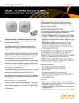
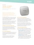
DATA SHEET
Aruba AP-120 and
AP-121 Access Points
ARUBA AP-120 AND AP-121 ACCESS POINTS
The multifunction AP-120 and AP-121 are indoor 802.11n access
points (APs) designed for maximum deployment flexibility in low-density
environments that require above-ceiling or enclosure-based installations.
These high-speed APs deliver wire-like performance at date rates up to 300
Mbps.
The AP-120 features a single 3x3 MIMO dual-band 2.4-GHz/5GHz radio with
detachable antenna interfaces while the AP-121 features the same radio
with integrated antenna elements. Both APs are built to provide years of
trouble-free operation and are backed by a limited lifetime warranty.
Working with Aruba’s line of centralized Mobility Controllers, the AP-120 and AP-121 deliver secure, high-speed network
services that move users to a “wireless where possible, wired where necessary” network access model. The network can then be
rightsized by eliminating unused Ethernet switch ports and thereby reducing operating costs.
802.11n enables the use of wireless as a primary connection with speed and reliability comparable to a wired LAN. It also
increases performance by utilizing techniques such as channel bonding, block acknowledgement and MIMO radios. Advanced
antenna technology also increases range and reliability.
The key to ensuring wire-like performance and reliability is Aruba’s unique Adaptive Radio Management and spectrum analysis*
capabilities, which manage the 2.4-GHz and 5-GHz radio bands to deliver maximum client performance while mitigating any RF
interference.
The multifunction AP-120 and AP-121 can be configured through the Mobility Controller to provide WLAN access with parttime air monitoring, dedicated air monitoring for wireless IPS and spectrum analysis, Remote AP (RAP) functionality or secure
enterprise mesh. The AP-120 and AP-121 feature dual 100/1000BASE-T Ethernet interfaces and operate from standard 802.3af
power-over-Ethernet (PoE) sources.
APPLICATION
• 802.11n indoor AP designed for maximum deployment flexibility in
low-density environments that require above-ceiling or enclosurebased installations.
OPERATING MODE
• 802.11a/b/g/n AP, air monitor (AM) and Remote AP (RAP)
• Spectrum monitor, AM and RAP
• AM and RAP
• Remote AP
• Secure enterprise mesh
RADIOS
• Software-configurable single radio capable of supporting 2.4 GHz or
5 GHz
RF MANAGEMENT
• Automatic transmit power and channel management control with
auto coverage hole correction via Adaptive Radio Management
(ARM)
• Spectrum analysis* remotely scans the 2.4-GHz and 5-GHz
radio bands to provide increased visibility into non-802.11n RF
interference sources and their effect on 802.11n channel quality.
ADVANCED FEATURES
• Integrated RAP, secure enterprise mesh point or portal, and wireless
intrusion detection and prevention
• Integrated Trusted Platform Module (TPM) for secure storage of
credentials and keys
• SecureJack-capable for secure tunneling of wired Ethernet traffic
WIRELESS RADIO SPECIFICATIONS
• AP type: Single-radio, dual-band 802.11n indoor
• Supported frequency bands (country-specific restrictions apply):
- 2.400 to 2.4835 GHz
- 5.150 to 5.250 GHz
- 5.250 to 5.350 GHz
- 5.470 to 5.725 GHz
- 5.725 to 5.850 GHz
• Available channels: Controller-managed, dependent upon
configured regulatory domain
• Supported radio technologies:
- 802.11b: Direct-sequence spread-spectrum (DSSS)
- 802.11a/g/n: Orthogonal frequency division multiplexing (OFDM)
- 802.11n: 3x3 MIMO with 2 spatial streams
• Supported modulation types:
- 802.11b: BPSK, QPSK, CCK
- 802.11a/g/n: BPSK, QPSK, 16-QAM, 64-QAM
• Transmit power: Configurable in increments of 0.5 dBm
• Maximum transmit power:
- 2.4 GHz: 23 dBm (limited by local regulatory requirements)
- 5 GHz: 22 dBm (limited by local regulatory requirements)
• Maximum ratio combining (MRC) for improved receiver performance
• Association rates (Mbps):
- 802.11b: 1, 2, 5.5, 11
- 802.11a/g: 6, 9, 12, 18, 24, 36, 48, 54
- 802.11n: MCS0 - MCS15 (6.5 Mbps to 300 Mbps)
• 802.11n high-throughput (HT) support: HT 20/40
• 802.11n packet aggregation: A-MPDU, A-MSDU
*Available Q3 2010
ARUBA AP-120 AND AP-121 ACCESS POINTS
ANTENNA
• AP-120: Three RP-SMA interfaces for external antenna support
(supports up to 3x3 MIMO with spatial diversity)
• AP-121: AP-121: Integral, tri, omni-directional multiband dipole
antenna elements (supports up to 3x3 MIMO with spatial diversity)
• AP-121 antenna max gain:
- 2.4 to 2.5 GHz/3.2 dBi
- 5.150 to 5.875 GHz/5.2 dBi
POWER
• 48 V DC 802.3af or 802.3at or PoE+
• 5 V DC for external AC supplied power (adapter sold separately)
• Maximum power consumption: 12 watts
INTERFACES
• Network:
- 2 x 100/1000BASE-T Ethernet (RJ-45), auto-sensing link speed and MDI/MDX
- 48 V DC 802.3af or 802.3at or PoE+ interoperable power-overEthernet (PoE) on both ports
• Antenna (model AP-120 only):
- 3 x RP-SMA antenna interfaces (supports up to 3x3 MIMO with spatial diversity)
• Other:
- 1 x RJ-45 console interface
MOUNTING
• Standard:
- Wall
- Tool-less ceiling tile rail (15/16”)
• Optional mounting kit:
- Desk-stand and wall-outlet mount plate
- Solid wall stand-off
- Ceiling tile rail (15/16” & 9/16” recessed or non-recessed)
• Security:
- Kensington security lock point (AP-121 only)
MECHANICAL
• Dimensions/weight:
- 124 mm x 130 mm x 51 mm (4.9” x 5.13” x 2.0“)
- 0.42 kg (15 oz)
ENVIRONMENTAL
• Operating:
- Temp: 0° C to 50° C +(32° F to +122° F)
- Humidity: 5 to 95% non-condensing
• Storage and Transportation Temperature Range:
- Temp: -40° C to +70° C (-40° F to +158° F)
REGULATORY
• FCC Part 15
• Industry of Canada
• MIC
• Anatel
• NOM/COFETEL
• SRRC / CCC
• GS Mark
• CE Mark
• R&TTE Directive - 1995/5/EC
• Low Voltage Directive - 72/23/EEC
• EN 300 328
• EN 301 893
• EN 301 489
• UL/IEC/EN 60950-1:2001
• CB, cULus
• AS/NZS 4268, 4771
• UL2043 Compliant
For more country-specific regulatory information and approvals,
please see your Aruba representative.
CERTIFICATIONS
• Wi-Fi certified: 802.11a/b/g/n
WARRANTY
• Limited lifetime warranty
ORDERING INFORMATION
Part number
Description
AP-120
Aruba 120 AP (802.11a/n or 802.11b/g/n only)
AP-121
Aruba 121 AP (802.11a/n or 802.11b/g/n only)
AP-AC-NA-2 AP-AC-JPN-2 AP-AC-UK-2 AP-AC-IT-2 AP-AC-EC-2 AP-AC-AUS-2 AP-AC-LA-2 AP-AC-CHN-2 AP-AC-IN-2 AP-AC-KOR-2 AP-120-MNT AP-120-MNT-WJ AP-120-MNT-CV
AP-ANT-xx AC Power Adapter Kit - North America
AC Power Adapter Kit - Japan
AC Power Adapter Kit - United Kingdom
AC Power Adapter Kit - Italy
AC Power Adapter Kit - Schuko
AC Power Adapter Kit - Australia
AC Power Adapter Kit - North America 2 Prong
Version
AC Power Adapter Kit - China
AC Power Adapter Kit - India
AC Power Adapter Kit - Korea
Aruba 120 Family Wireless Access Point
desktop/wall / ceiling mounting kit
Mounting hardware kit and product enclosure
to facilitate secure wall or ceiling mounting of
an Aruba AP-121 or AP-125 access point to a
standard North American or BS telecom/data
port wall gang box, or to a 15/16” or 9/16” ceiling
tile rail.
Cabling cover mounting kit to to facilitate tamper
- proof mounting of an Aruba AP-121 or AP-125
access point.
Detachable antennas (for use with AP-120 only)
ARUBA AP-120 AND AP-121 ACCESS POINTS
RF PERFORMANCE TABLE
Max TX power per
active TX chain
(dBm)
RX Sensitivity
(dBm)
Max TX power per
active TX chain
(dBm)
2.4 GHz
802.11b
1 Mbps
2 Mbps
5.5 Mbps
11 Mbps
802.11a/g
6 Mbps
9 Mbps
12 Mbps
18 Mbps
24 Mbps
36 Mbps
48 Mbps
54 Mbps
RX Sensitivity
(dBm)
5 GHz
+18
+18
+18
+18
-93
-91
-90
-88
+17
+17
+17
+17
+17
+17
+16
+13
-92
-92
-92
-91
-88
-85
-81
-79
+17
+17
+17
+17
+17
+16
+15
+13
-91
-91
-91
-90
-87
-83
-79
-77
+18
+18
+18
+18
+18
+17
+13
+11
+18
+18
+18
+18
+18
+17
+13
+11
-92
-91
-89
-85
-82
-78
-76
-75
-90
-89
-87
-83
-80
-76
-74
-73
+17
+17
+17
+17
+17
+17
+13
+12
+17
+17
+17
+17
+17
+17
+13
+12
-91
-89
-87
-84
-80
-76
-74
-72
-89
-87
-85
-82
-78
-74
-72
-70
+18
+18
+18
+18
+18
+17
+13
+11
+18
+18
+18
+18
+18
+17
+13
+11
-89
-87
-84
-84
-78
-74
-72
-71
-87
-85
-82
-82
-76
-72
-70
-69
+17
+17
+17
+17
+17
+17
+13
+12
+17
+17
+17
+17
+17
+17
+13
+12
-88
-85
-83
-80
-77
-72
-70
-67
-86
-83
-81
-78
-75
-70
-68
-65
802.11n HT20
MCS0
MCS1
MCS2
MCS3
MCS4
MCS5
MCS6
MCS7
MCS8
MCS9
MCS10
MCS11
MCS12
MCS13
MCS14
MCS15
802.11n HT40
MCS0
MCS1
MCS2
MCS3
MCS4
MCS5
MCS6
MCS7
MCS8
MCS9
MCS10
MCS11
MCS12
MCS13
MCS14
MCS15
Maximum capability of the hardware provided. Maximum transmit power will be limited by local regulatory settings.
ARUBA AP-120 AND AP-121 ACCESS POINTS
ANTENNA PLOTS
Z
Y
Y
X
2.45 GHz
2.450GHz, YZ
2.450GHz, XY, -90
325
330
335
340
0
355
345 350
5
5
10 15
20
25
0
320
315
30
-35
35
305
295
Y
-65
65
-20
275
270
80
-80
85
-85
90
-90
95
-95
100
-100
X
-30
265
260
255
105
250
240
195 190
185
165
175 170
180
160
155
150
75
80
Y
85
90
-30
95
100
-105
105
110
115
-120
120
-125
125
-130
135
140
200
65
-25
125
205
60
70
130
210
55
-20
120
235
50
Z
-115
115
215
35
-110
110
245
225
220
30
-15
-75
75
230
25
-70
70
-25
20
45
-10
-60
60
290
280
10 15
40
-55
55
-15
285
5
-5
-50
50
-10
300
0
5
0
-45
45
-5
-5
-15 -10
-20
-40
40
310
-30
-25
130
-135
-140
-145
-150
-155
145
135
140
-160
-165 -170
H-Plane
-175
165
175 170
180
160
155
150
145
E-Plane
5.5 GHz
5.500GHz, YZ
5.500GHz, XY, -90
325
330
335
340
355
345 350
5
0
5
10 15
20
25
0
320
315
30
-35
35
310
305
-10
300
295
45
50
Y
80
X
85
90
-30
265
95
260
100
255
105
250
110
245
115
240
120
235
125
130
225
220
135
140
215
210
205
200
195 190
185
180
165
175 170
160
155
150
145
20
25
30
35
45
-10
50
55
Z
60
65
-15
-70
75
230
10 15
40
-65
65
-20
270
5
-5
-60
60
70
275
0
5
0
-55
55
-25
-5
-50
290
280
-15 -10
-45
-15
285
-20
-40
40
-5
-30
-25
70
-20
-75
-80
75
80
-25
-85
-90
Y
85
90
-30
95
-95
100
-100
-105
105
-110
110
-115
115
-120
120
-125
125
-130
130
-135
-140
-145
-150
-155
H-Plane
WWW.ARUBANETWORKS.COM
135
140
-160
-165 -170
-175
180
165
175 170
160
155
150
145
E-Plane
| 1344 Crossman Avenue. Sunnyvale, CA 94089
1-866-55-ARUBA | Tel. +1 408.227.4500 | Fax. +1 408.227.4550 | [email protected]
© 2010 Aruba Networks, Inc. AirWave®, Aruba Networks®, Aruba Mobility Management System®, Bluescanner, For Wireless That Works®, Mobile Edge Architecture®, People Move. Networks Must Follow®, RFprotect®, The All
Wireless Workplace Is Now Open For Business, Green Island, and The Mobile Edge Company® are trademarks of Aruba Networks, Inc. All rights reserved. Aruba Networks reserves the right to change, modify, transfer, or otherwise
revise this publication and the product specifications without notice. While Aruba uses commercially reasonable efforts to ensure the accuracy of the specifications contained in this document, Aruba will assume no responsibility for
any errors or omissions. Note: All scaling metrics outlined in this document are maximum supported values. The scale may vary depending upon the deployment scenario and features enabled.
DS_AP120121_US_100524