1
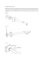
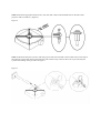
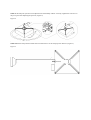
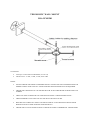
TELESCOPIC WALL MOUNT
POA-WMST01
CONTENTS
•
•
Telescopic wall mount POA-WMST01 (93-156 cm)
Thread screws: 4 x M3, 4 x M4, 4 x M5, and 4 x M6
HINTS:
•
PLEASE CHECK THE PRODUCT BEFORE INSTALLATIONS FOR ANY DEFORMATIONS OR
MISSING PARTS AND CONTACT YOUR SUPPLIER FOR MAINTENANCE IF REQUIRED.
•
CHECK THE USER MANUAL OF THE PROJECTOR TO SET THE PROJECTOR DISTANCE TO
SCREEN.
•
THE WALL MOUNT SHOULD ONLY BE INSTALLED BY A TRAINED SPECIALIST .
•
THE MAXIMUM LOAD CAPACITY OF THE WALL MOUNT IS 20 KG.
•
BE SURE THAT THE WALL MOUNT IS INSTALLED IN A SAFE POSITION ABOVE HEAD
HEIGHT AND NOT OVER EXISTING PASSAGEWAYS.
•
CHECK THE LOCAL/NATIONAL REGULATIONS IN PUBLIC/COMMERCIAL USED ROOMS.
INSTRUCTIONS FOR USE:
STEP 1: The telescopic wall mount should be fixed to the wall horizontally by a trained specialist using the
right kind of screws according to the structure of the wall ( Figure 1a). Conceal the cables inside the cable duct
and prevent the cables from damage during the process and be aware that the product is conductive, never use
unisolated cables. ( Figure 1 b).Tighten the cable cover part with the plastic ring to the body of the wall mount (
Figure 1c).
Figure 1a
Figure 1 b
Figure 1c
STEP 2: Mount the appropiate thread screws ( M3, M4, M5 or M6) in the threaded holes on the base of the
projector with a screwdriver ( Figure 2).
Figure 2
STEP 3: Mount the ball joint systeme ( after the projector has been mounted to the movable arms) to the body of
the telescopic wall mount which was fixed to the wall in the first step. Then fix the screw to prevent ball joint
systeme from falling on the ground as in Figure 3.
Figure 3
STEP 4: The ball joint systeme can be adjusted 360° horizantally and 20° vertically. Tighten the cam lever on
the pivot point after adjusting the position ( Figure 4)
Figure 4
STEP 5:Push the safety button towards the arrow direction to set the wall-projector distance ( Figure 5).
Figure 5