1
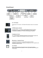
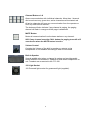
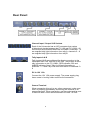
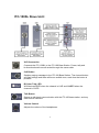
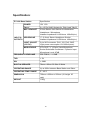
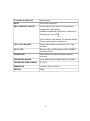
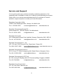
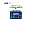
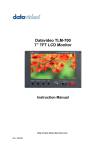
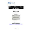
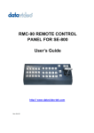
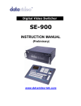
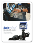
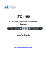
ITC100 8 Channel Intercom / Talkback System User’s Guide http:// www.datavideotek.com Rev: 300506 Warnings and Precautions 1. Read all of these warnings and save them for later reference. 2. Follow all warnings and instructions marked on this unit. 3. Unplug this unit from the wall outlet before cleaning. Do not use liquid or aerosol cleaners. Use a damp cloth for cleaning. 4. Do not use this unit in or near water. 5. Do not place this unit on an unstable cart, stand, or table. The unit may fall, causing serious damage. 6. Slots and openings on the cabinet top, back, and bottom are provided for ventilation. To ensure safe and reliable operation of this unit, and to protect it from overheating, do not block or cover these openings. Do not place this unit on a bed, sofa, rug, or similar surface, as the ventilation openings on the bottom of the cabinet will be blocked. This unit should never be placed near or over a heat register or radiator. This unit should not be placed in a builtin installation unless proper ventilation is provided. 7. This product should only be operated from the type of power source indicated on the marking label of the AC adapter. If you are not sure of the type of power available, consult your Datavideo dealer or your local power company. 8. Do not allow anything to rest on the power cord. Do not locate this unit where the power cord will be walked on, rolled over, or otherwise stressed. 9. If an extension cord must be used with this unit, make sure that the total of the ampere ratings on the products plugged into the extension cord do not exceed the extension cord’s rating. 10. Make sure that the total amperes of all the units that are plugged into a single wall outlet do not exceed 15 amperes. 11. Never push objects of any kind into this unit through the cabinet ventilation slots, as they may touch dangerous voltage points or short out parts that could result in risk of fire or electric shock. Never spill liquid of any kind onto or into this unit. 12. Except as specifically explained elsewhere in this manual, do not attempt to service this product yourself. Opening or removing covers that are marked “Do Not Remove” may expose you to dangerous voltage points or other risks, and will void your warranty. Refer all service issues to qualified service personnel. 13. Unplug this product from the wall outlet and refer to qualified service personnel under the following conditions: a. When the power cord is damaged or frayed; b. When liquid has spilled into the unit; c. When the product has been exposed to rain or water; d. When the product does not operate normally under normal operating conditions. Adjust only those controls that are covered by the operating instructions in this manual; improper adjustment of other controls may result in damage to the unit and may often require extensive work by a qualified technician to restore the unit to normal operation; e. When the product has been dropped or the cabinet has been damaged; f. When the product exhibits a distinct change in performance, indicating a need for service. 1 Warranty Datavideo warrants that the equipment it manufactures shall be free from defects in material and workmanship for a period of 12 months from the date of product purchased. If equipment fails due to such defects, Datavideo will, at its option, repair or provide a replacement for the defective part or product. Equipment that fails after the warranty period, has been operated or installed in a manner other than that specified by Datavideo, or has been subjected to abuse or modification, will be repaired for time and material charges at the Buyer’s expense. This warranty does not affect your statutory rights within the Country of purchase. For EU Customers only WEEE Marking. This symbol on the product indicates that it will not be treated as household waste. It must be handed over to the applicable takeback scheme for the recycling of electrical and electronic equipment. For more detailed information about the recycling of this product, please contact your local Datavideo office. Introduction The ITC100 is a 19” Rack Mount 8 Way Intercom / Talkback System. It incorporates tally indicators for each channel and individual channel call buttons as well as a call all channels button. It is ideal in a live environment and enables easy bidirectional communication between all members of the crew. It is a perfect accessory for the Datavideo SE800 and SE500 vision mixers. 2 Contents WARNINGS AND PRECAUTIONS 1 WARRANTY 2 INTRODUCTION 2 WHAT’S IN THE PACKAGE 3 FRONT PANEL CONNECTIONS 4 REAR PANEL CONNECTIONS 6 ITC100SL SLAVE UNIT 7 USING THE ITC100 WITH THE SE800 / RMC140 9 USING THE ITC100 WITH THE SE800 / RMC90 10 USING THE ITC100 WITH THE SE500 11 ITC100 TALLY INPUT PIN CROSS REFERENCE 12 SPECIFICATIONS 13 SERVICE AND SUPPORT 15 What’s in the Package 1. ITC100 main unit x 1 2. ITC100SL Slave Unit x 4 3. ITC100SL Carrying Case x 4 4. 20m XLR to XLR Intercom Cable x 4 5. MC1 Headset / Microphone x 4 6. MC2 XLR Gooseneck Mic x 1 7. LP1 XLR Gooseneck Light x 1 8. 12V 2.5A Power Supply Unit x 1 9. AC Power cord. x 1 10.User’s Guide x 1 3 Front Panel: On / Off Switch Powers the ITC100 On / Off. Red LED indicates that unit is switched on. XLR Microphone Socket Combined XLR / ¼” (6.3mm) Jack Microphone Input for either a Condenser or Dynamic Gooseneck Microphone. XLR supports Condenser Microphones ¼” (6.3mm) Jack supports Dynamic. Headphone Socket ¼ “ / 6.3mm Stereo Headphone Socket for conventional headphones. Plugging in headphones will disable the builtin speaker Microphone / Headset Socket 3.5mm Stereo Socket for combined Microphone Headset. Plugging in a Microphone / Headset will disable the builtin speaker and the XLR Microphone Input. ALL Button Opens communication with all channels. All channels will hear communication from the operator, or from any other channel using the TALK button. 4 Channel Buttons 1~8 Opens communication with individual channels. More than 1 channel can be active at any given time, active channels are illuminated red. All active channels will hear any communication from the operator or from any other active channel. The buttons will also indicate if any channel is paging, the paging channel will flash in orange until the page is answered. MUTE Button Mutes all communication from the base station or any channel. N.B. If any channel uses the CALL button the paging tone will still sound even when the MUTE button is active. Volume Control Controls the Volume of the builtin speaker or outputs to the headphones or mic/headset according to what is connected BuiltIn Speaker Sounds audible alert when a channel is paging and provides audio during talkback conversations. Speaker is mute when headphones or mic / headset are connected to the ITC100 12V Light Socket 12V Powered light socket for gooseneck light (supplied). 5 Rear Panel: Channel Input / Output XLR Sockets Each of the 8 channels has an XLR connector that carries bidirectional signals between the ITC100 and ITC100SL. All connections are contained within the one cable. Channels 1 ~ 4 are supplied tally light information from tally A; channels 5 ~ 8 are supplied tally light information from tally B. Tally Inputs A & B Tally Inputs A & B are configured for direct connection to the Datavideo RMC140, RMC90 or SE500. They supply bicolor tally information to the ITC100SL; RED indicates Live and AMBER indicates Cued. Tally A will feed information to channels 1 ~ 4 and Tally B will feed information to channels 5 ~ 8 DC In 12V 1.5A Connect the 12V 1.5A power supply. The power supply plug has a screw in locking collar to secure the connection. Ground Terminal When connecting this unit to any other component, make sure that it is properly grounded by connecting this terminal to an appropriate point. When connecting, use the socket and be sure to use wire with a crosssectional area of at least 1.0 mm2. 6 ITC100SL Slave Unit : XLR Connection Connects the ITC100SL to the ITC100 Base Station. Power, tally and bidirectional audio are all carried through the same cable. Call Button Sends a paging message to the ITC100 Base Station. The channel button will flash orange and there will be an audible tone, each time the button is pressed. BiColor Tally LED Will illuminate RED when the channel is LIVE and AMBER when the channel is CUED Talk Button Opens up talk back communication with the ITC100 base station, and any other active channels. Volume Control Adjusts the volume of the headphones. 7 Mic / Headphone Socket The ITC100SL has both a 3.5mm and 2.5mm Mic / Headset socket. A standard 3.5mm Mic / Headset can be used, or a Motorola type 2.5mm Mic / headset could be used if preferred. External Tally LED Socket An external tally display (TD1) can be connected to the ITC100SL. This enables the tally light to be positioned in a more convenient place, such as on top of the camera. When the channel is LIVE the LED will be RED, and when the channel is CUED the LED will be AMBER. N.B. The Tally LED on the ITC100SL will continue to operate as normal when a TD1 has been added. Power LED The Power LED indicates when the channel is active. If the operator has opened the channel by pressing the channel button 1 ~ 8, or by pressing ALL then the LED will light up. N.B. The tally indicator lights will continue to work even when the Power LED is not on, and the channel is not active. 8 Using the ITC100 with the SE800 / RMC140: The ITC100 is an ideal accessory for the Datavideo SE800 / SE800AV Vision Mixer. The SE800 has four channels, so in the diagram below we have four camera crew, each with an ITC100SL The RS232 output from the SE800 connects to the RMC140; this provides the status of the SE800. The RMC140 Tally Out connects to the ITC100 Tally Input A. Tally Input A provides tally information to channels 1 ~ 4. When the camera is live the cameraman will see a red light, when a camera is cued up the cameraman will see an amber light. 9 Using the ITC100 with the SE800 / RMC90: Using the Datavideo SE800 / SE800AV Vision Mixer in combination with the RMC90 remote control makes live production really simple. The RS232 output from the SE800 connects to the RMC90; this provides the status of the SE800. The RMC90 Tally Out connects to the ITC100 Tally Input A. Tally Input A provides tally information to channels 1 ~ 4. When the camera is live the cameraman will see a red light, when a camera is cued up the cameraman will see an amber light. 10 Using the ITC100 with the SE500: The ITC100 is an ideal accessory for the Datavideo SE500 Vision Mixer. The SE500 has four channels, so in the diagram below we have four camera crew, each with an ITC100SL. The SE500 Tally Out connects to the ITC100 Tally Input A. Tally Input A provides tally information to channels 1 ~ 4. When the camera is live the cameraman will see a red light, when a camera is cued up the cameraman will see an amber light. 11 ITC100 Tally Input Pin Cross Reference If you are using the ITC100 with a Datavideo RMC140, RMC90 or SE500 you do not need to worry about tally information, as it is automatically sent to the ITC100. If you are using the ITC100 with other equipment the following tables explain the pin configurations of Tally A and Tally B. Contact closure between the relevant Pin number and ground will illuminate the LED. For example on Tally A, if Pin 1 is connected to Pin 4 the RED LED will light up on Channel 1; if Pin 13 is connected to Pin 4 the AMBER LED will light up on Channel 3 Tally A Input The Tally A Input will send Tally Information to Channels 1 ~ 4. The following table shows the pin numbers for each channel: Video Channel Red LED LIVE (On Air) Amber LED CUED (Next) 1 Pin 1 Pin 3 2 Pin 6 Pin 8 3 Pin 11 Pin 13 4 Pin 5 Pin 15 Pins 4, 9 and 14 can be used as ground. Tally B Input The Tally B Input will send Tally Information to Channels 5 ~ 8. The following table shows the pin numbers for each channel: Video Channel Red LED LIVE (On Air) Amber LED CUED (Next) 5 Pin 1 Pin 3 6 Pin 6 Pin 8 7 Pin 11 Pin 13 8 Pin 5 Pin 15 Pins 4, 9 and 14 can be used as ground. 12 Specification: ITC100 Base Station Specification POWER 12V 1.5A TALLY 2 x 15 Pin SubD Sockets for Tally A and Tally B MIC / HEADSET 3.5mm Stereo Jack Socket for combination Headphone / Microphone Headset Impedance 8~600 ohms 100mW(min) INPUTS / HEADPHONE OUTPUTS ¼” (6.3mm) Stereo Headphone Socket Headset Impedance 8~600 ohms 100mW(min) LIGHT SOCKET 3 pin XLR connector. Pin2: 12V, Pin3: GND. (12V DC) Light power consumption 12V/100mA(max). MICROPHONE 3 Pin XLR / ¼” (6.3mm) Jack Microphone Socket Switchable Condenser / Dynamic Input Microphone Level 67dB FREQUENCY RESPONSE 5503.6KHz, < +/3dB THD < 3% S/N > 50dB BUILTIN SPEAKER 70mm x 30mm 32 Ohm 3 Watts OPERATING RANGE Up to 200m between Base Station and Slave OPERATING TEMP. RANGE 5 ~ 45°C DIMENSION 750mm x 650mm x 250mm (1U height 19” rack) WEIGHT 1.9Kg 13 ITC100SL SLAVE Unit Specification INPUT 5 Pin XLR Connector MIC / HEADSET SOCKET 3.5mm Stereo Jack Socket for combination Headphone / Microphone Headset Impedance 8~600 ohms 100mW(min) Microphone Level 67dB Or 2.5mm Stereo Jack Socket, for Motorola Mobile Phone type headset / microphone TALLY OUT SOCKET 3.5mm Jack Socket to connect to TD1 Tally Indicator TALLY LED BiColor LED – RED indicates LIVE / AMBER Indicates CUED POWER LED Illuminates to indicate that power is being received OPERATING RANGE Up to 200m between Base Station and Slave OPERATING TEMP. RANGE 5 ~ 45°C DIMENSION 114mm x 97mm x 35mm WEIGHT 348g 14 Service and Support It is our goal to make your products ownership a satisfying experience. Our supporting staff is available to assist you in setting up and operating your system. Please refer to our web site www.datavideotek.com for answers to common questions, support requests or contact your local office below. Datavideo Corporation (USA) 12300U East Washington Blvd., Whittier, CA 90606 USA Tel: +1 562 696 2324 [email protected] www.datavideo.us Datavideo Technologies Europe BV Californiedreef 26 3565 BL Utrecht, The Netherlands Tel: +31 30 261 9656 [email protected] www.datavideo.info Datavideo UK Limited Unit 2 Waterside Business Park, Hadfield, Glossop, Derbyshire SK13 1BE UK Tel: +44 1457 851000 [email protected] www.datavideo.info Datavideo Technologies Co., Ltd. 10F, 176 JianYi Rd, Chung Ho City, Taipei Hsien, Taiwan 235 Tel: +886 2 8227 2888 [email protected] www.datavideo.com.tw Datavideo Technologies China Co. 2FD, 2 Lane 777, West Guangzhong Rd, Zhabei District, Shanghai, China Tel: +86 21 5603 6599 [email protected] www.datavideo.cn Datavideo Technologies (S) PTE Ltd. No. 100, Lorong 23 Geylang, #0103 D’Centennial Bldg, Singapore 388398 Tel: +65 6749 6866 [email protected] www.datavideo.info Datavideo Hong Kong Limited G/F., 26 Cross Lane, Wanchai, HK Tel: +852 2833 1981 [email protected] 15 www.datavideohk.com