1
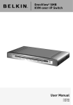
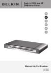
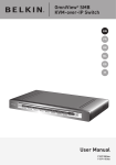
OmniView® SMB CAT5
216/232 Switch
User Manual
PM00019 -F1DP2XXA
Table of Contents
Table of Contents
sections
1
2
3
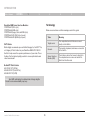
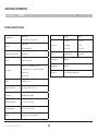
Introduction . . . . . . . . . . . . . . . . . . . . . . . . . . . . . . . . . . . . . . . . . . . . .
Key Features . . . . . . . . . . . . . . . . . . . . . . . . . . . . . . . . . . . . . . . . . . .
System Contents . . . . . . . . . . . . . . . . . . . . . . . . . . . . . . . . . . . . . . . .
System Requirements . . . . . . . . . . . . . . . . . . . . . . . . . . . . . . . . . . . .
Terminology . . . . . . . . . . . . . . . . . . . . . . . . . . . . . . . . . . . . . . . . . . . .
Unit Display Diagrams . . . . . . . . . . . . . . . . . . . . . . . . . . . . . . . . . . . .
LED and button table . . . . . . . . . . . . . . . . . . . . . . . . . . . . . . . . . .
Connector table . . . . . . . . . . . . . . . . . . . . . . . . . . . . . . . . . . . . . . .
1
2
4
4
5
6
6
6
Installation . . . . . . . . . . . . . . . . . . . . . . . . . . . . . . . . . . . . . . . . . . . . . . 7
Pre-Installation Guidelines . . . . . . . . . . . . . . . . . . . . . . . . . . . . . . . . 7
Avoiding general rack-mounting problems . . . . . . . . . . . . . . . . . 7
Rack-mounting the SMB CAT5 Switch . . . . . . . . . . . . . . . . . . . . 8
Connecting the System . . . . . . . . . . . . . . . . . . . . . . . . . . . . . . . . . . . 9
The Server Interface Modules (SIMs) . . . . . . . . . . . . . . . . . . . . . 10
Connecting a PS/2 SIM . . . . . . . . . . . . . . . . . . . . . . . . . . . . . 11
Connecting a USB SIM . . . . . . . . . . . . . . . . . . . . . . . . . . . . . 11
Connecting to the network . . . . . . . . . . . . . . . . . . . . . . . . . . . . . 12
Connecting the CAT5 cables . . . . . . . . . . . . . . . . . . . . . . . . . . . 12
Connecting the local console . . . . . . . . . . . . . . . . . . . . . . . . . . . 12
Connecting the power supply . . . . . . . . . . . . . . . . . . . . . . . . . . 12
Setting the IP Address . . . . . . . . . . . . . . . . . . . . . . . . . . . . . . . . . . . 13
Web Interface . . . . . . . . . . . . . . . . . . . . . . . . . . . . . . . . . . . . . . . . . . .
Logging In to the Web Interface . . . . . . . . . . . . . . . . . . . . . . . . . . .
SSL certificate notes . . . . . . . . . . . . . . . . . . . . . . . . . . . . . . . . . .
Logging in . . . . . . . . . . . . . . . . . . . . . . . . . . . . . . . . . . . . . . . . . .
Configuring the System . . . . . . . . . . . . . . . . . . . . . . . . . . . . . . . . . .
Network > Configuration . . . . . . . . . . . . . . . . . . . . . . . . . . . . . . .
LAN . . . . . . . . . . . . . . . . . . . . . . . . . . . . . . . . . . . . . . . . . . . . .
OmniView® SMB CAT5 216/232 Switch
15
15 15
16
17
17
18
i
4
5
Administration > User Settings . . . . . . . . . . . . . . . . . . . . . . . . . . . . . .
Adding a user . . . . . . . . . . . . . . . . . . . . . . . . . . . . . . . . . . . . . . .
Editing a user . . . . . . . . . . . . . . . . . . . . . . . . . . . . . . . . . . . . . . . .
Deleting a user . . . . . . . . . . . . . . . . . . . . . . . . . . . . . . . . . . . . . .
Blocking a user . . . . . . . . . . . . . . . . . . . . . . . . . . . . . . . . . . . . . .
Administration > Server Name Edit . . . . . . . . . . . . . . . . . . . . . . . .
Administration > Server Access List . . . . . . . . . . . . . . . . . . . . . . . .
Security > Settings . . . . . . . . . . . . . . . . . . . . . . . . . . . . . . . . . . . . .
Security > SSL Certificate . . . . . . . . . . . . . . . . . . . . . . . . . . . . . . . .
Maintenance > Switch Upgrade . . . . . . . . . . . . . . . . . . . . . . . . . . .
Maintenance > SIM Upgrade . . . . . . . . . . . . . . . . . . . . . . . . . . . . .
Restore Factory Settings . . . . . . . . . . . . . . . . . . . . . . . . . . . . . . . . .
Set Time and Date . . . . . . . . . . . . . . . . . . . . . . . . . . . . . . . . . . . . . .
Back Up and Restore . . . . . . . . . . . . . . . . . . . . . . . . . . . . . . . . . . .
Saving Changes and Logging Out . . . . . . . . . . . . . . . . . . . . . . . . .
18
19
20
20
20
20
21
21
22
23
23
24
24
25
25
Local Access . . . . . . . . . . . . . . . . . . . . . . . . . . . . . . . . . . . . . . . . . . . .
The OSD . . . . . . . . . . . . . . . . . . . . . . . . . . . . . . . . . . . . . . . . . . . . . .
Navigating the OSD Main window . . . . . . . . . . . . . . . . . . . . . . .
Selecting a computer . . . . . . . . . . . . . . . . . . . . . . . . . . . . . . . . .
Moving the confirmation label – F1 . . . . . . . . . . . . . . . . . . . . . .
Tuning – F5 . . . . . . . . . . . . . . . . . . . . . . . . . . . . . . . . . . . . . . . . .
The Settings window – F2 . . . . . . . . . . . . . . . . . . . . . . . . . . . . .
DDC – F10 . . . . . . . . . . . . . . . . . . . . . . . . . . . . . . . . . . . . . . . . . .
Saving changes to the settings . . . . . . . . . . . . . . . . . . . . . . . . .
26
26
26
26
27
27
28
29
29
Additional Information . . . . . . . . . . . . . . . . . . . . . . . . . . . . . . . . . . .
Technical Specifications . . . . . . . . . . . . . . . . . . . . . . . . . . . . . . . . .
Safety . . . . . . . . . . . . . . . . . . . . . . . . . . . . . . . . . . . . . . . . . . . . . . . .
User Manual Feedback . . . . . . . . . . . . . . . . . . . . . . . . . . . . . . . . . .
Product Registration . . . . . . . . . . . . . . . . . . . . . . . . . . . . . . . . . . . .
Information . . . . . . . . . . . . . . . . . . . . . . . . . . . . . . . . . . . . . . . . . . . .
30
30
31
31
31
32
Introduction
Table of Contents
sections
1
2
3
4
5
Congratulations and thank you for purchasing the Belkin OmniView SMB CAT5 216/232 Switch with advanced CAT5 extension
technology. This Switch provides a simple, quick, server management solution for medium to large-size businesses. The Switch
allows multiuser access and control of multiple servers.
This User Manual provides all the details you’ll need to install and operate your new OmniView SMB CAT5 216/232 Switch. For quick
and easy installation, please refer to the Quick Installation Guide included in your packaging.
We appreciate your business and are confident that you will soon see for yourself why over 1 million Belkin OmniView KVM
products are in use worldwide.
OmniView® SMB CAT5 216/232 Switch
1
Introduction
Table of Contents
sections
1
2
3
4
5
Key Features
CAT5 Technology
Integrated CAT5 technology enables you to connect your KVM Switch to your servers up to 100 feet (30m) away using standard
CAT5 cabling and Belkin’s compact Server Interface Modules (SIMs). CAT5 cabling reduces wiring clutter, simplifies cable
management, and allows for greater airflow in your racks, increasing the lifespan of your equipment. SIMs enable continuous server
uptime using keep-alive intelligence and keyboard and mouse signal emulation.
On-Screen Display (OSD)
The OSD feature simplifies server management by allowing you to assign individual names to each connected server throughout the
system. It provides a visual means of switching between servers and setting network parameters.
Hot Keys
Hot-key functionality allows you to select a desired port using designated key commands. By using a simple hot-key sequence on
your keyboard, you can select one server instantly.
Out of Band—BIOS-Level Access
The Switch allows you to locally access the basic input/output system (BIOS) of your servers to make changes and perform reboots,
regardless of network connectivity or server condition.
OmniView® SMB CAT5 216/232 Switch
2
Introduction
Table of Contents
sections
1
2
3
4
5
User-Friendly Interface
The web-based interface allows you to set up and change the Switch’s functions quickly and easily through your web browser,
without having to install additional software onto your servers.
Video Resolution
The Switch supports video resolutions of up to 1600x1200@75Hz for both local and remote consoles.
Flash-Upgradeable
Flash upgrades allow you to obtain the latest firmware updates for your Switch. These firmware updates ensure that the Switch is
compatible with the latest devices.
OmniView® SMB CAT5 216/232 Switch
3
Introduction
Table of Contents
sections
1
2
3
System Contents
•
1 OmniView SMB CAT5 216/232 Switch
•
1 AC Power Cable
•
1 User Manual CD
•
1 Quick Start Guide
•
1 Set Rack-Mount Brackets and Screws
•
Microsoft® DOS 5.x and above
•
Red Hat® Linux® 8.x and above
•
Sun™*
•
Novell® 5.x
•
Sun Solaris™ 8.x and above*
PS/2 and USB computers/servers
•
VGA, SVGA, or XGA monitors
•
USB-compatible
Monitors
•
CRT and LCD (with VGA, SVGA, or XGA monitors)
Server Interface Modules
Connecting the Switch to a server requires a custom Belkin OmniView
SMB Server Interface Module and a standard CAT5 patch cable.
*USB server interface module required
OmniView® SMB CAT5 216/232 Switch
•
Keyboards and Mice
Host Computer Operating-System (OS) Platforms
The Switch is compatible with CPUs running on, but not limited to,
the following OS platforms:
Windows® 2000, XP, Server 2003 and 2008, Vista®
5
Servers
System Requirements
•
4
4
Introduction
Table of Contents
sections
1
2
3
5
Terminology
OmniView SMB Server Interface Modules:
F1DP101A-AP (PS/2 style)
F1DP101A-AU (USB style)
F1DP101A-AS (Legacy Sun, miniDIN8 style)
F1DP101A-AP-8PK (PS/2 style, 8-pack)
F1DP101A-AU-8PK (USB style, 8-pack)
Below are some terms and their meanings used in this guide.
CAT5 Cables
Belkin highly recommends you use Belkin Category 5e, FastCAT™ 5e,
or Category 6 Patch Cables for your OmniView SMB CAT5 216/232
Switch to help ensure the superior performance of your video. These
Cables offer the highest quality possible to ensure optimal data and
video transmission.
Belkin UTP Patch Cables:
A3L791-XX-YYY (CAT5e)
A3L850-XX-YYY (FastCAT 5e)
A3L980-XX-YYY (CAT6)
Note: Use CAT6 solid cables for optimal video at longer lengths.
Product codes and availability may vary.
OmniView® SMB CAT5 216/232 Switch
4
5
Term
Meaning
Target server
The computers/servers that are accessed
locally via the Switch.
Console
The monitor, keyboard, and mouse connected
to the Switch.
Server Interface
Module (SIM)
The interface device that connects directly to
the computer/server on one end and to the
Switch on the other end.
J<I@8C(
J
<
I
)
Introduction
GFN<I
(''$)+'M8:,'&-'?q
MD(
CF:8CLJ<I
MD)
sections
Table of Contents
1
2
3
4
5
Analog
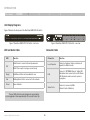
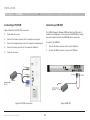
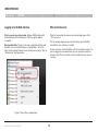
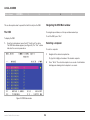
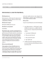
Unit Display Diagrams
Figure
1 illustrates the front panel of the OmniView SMB CAT5 232 Switch.
Analog
Lj\i(
Lj\i)
GFN<I
(''$)+'M8:,'&-'?q
Figure 1 OmniView SMB CAT5 232 Switch – front view
Figure 2 OmniView SMB CAT5 232 Switch – rear view
LED and button table
Lj\i(
Connector table
Lj\i)
GFN<I
(''$)+'M8:,'&-'?q
LED
Function
Connector
Function
Solid: Server is connected to and powered on
Local Consoles
Connect a keyboard, video, and mouse to
operate the Switch locally.
LAN
Connect to 10/100Mb Ethernet. Yellow LED
illuminates when connected to a LAN. Green
LED illuminates when a remote session is
in progress.
Server Ports
Connect to servers via SIMs
(Server Interface Modules).
Port
Blink: When a port is being accessed locally
Ready
Solid Green: When unit is available for use
Link
Blinking Green: Unit is connected to the network
Power
Power Indicator
Note: The port LEDs flash in series during boot up and during
system upgrades. Allow approximately 45 seconds for boot up.
OmniView® SMB CAT5 216/232 Switch
6
INSTALLATION
Table of Contents
sections
1
2
3
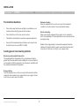
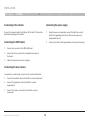
Pre-Installation Guidelines
•
Place cables away from fluorescent lights, air conditioners, and
machines that are likely to generate electrical noise.
•
Place the Switch on a flat, clean, and dry surface.
•
The Switch is not intended for connection to exposed outdoor lines.
•
Ensure that the maximum distance between each computer and
the Switch does not exceed 100 ft. for SIMs.
5
Mechanical loading
Mount the equipment in the rack in such a way that a hazardous
condition is not achieved due to uneven mechanical loading.
Circuit overloading
When connecting the equipment to the supply circuit, consider the
effect that overloading of circuits might have on over-current protection
and supply wiring.
Reliable electrical grounding of rack-mounted equipment should be
maintained. Provide attention to supply connections other than direct
connections to the branch circuit (e.g., use of power strips).
Avoiding general rack-mounting problems
Elevated operating ambient temperature
The operating ambient temperature of the rack environment may be
greater than the room ambient when installing into a closed or multiunit
rack assembly. Install the equipment in an environment compatible with
the maximum rated ambient temperature.
Reduced airflow
Install the equipment in a rack in such a way that the amount of airflow
required for safe operation is not compromised. Leave a gap of at least
5cm/2 inches on each side of the Switch.
OmniView® SMB CAT5 216/232 Switch
4
7
INSTALLATION
Table of Contents
sections
1
2
3
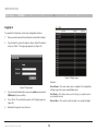
Rack-mounting the SMB CAT5 Switch
5
Place the brackets toward the front of the unit so that the unit can be
mounted front facing; or place the brackets toward the rear of the unit
so that it can be mounted rear facing on the back of a rack. Figure 4
illustrates the bracket connected for rear facing. Screw the bracket to
the Switch using the screws provided
Rack-mount the Switch using the supplied rack-mount kit. The brackets
can be placed in two possible positions (see Figure 3).
Figure 3 Bracket positions
OmniView® SMB CAT5 216/232 Switch
4
Figure 4 Bracket connected
8
INSTALLATION
Table of Contents
sections
1
2
3
Connecting the System
Figure 5 illustrates the Switch’s system overview.
CAT5 Cables (up to 100 ft.)
SMB CAT5 216/232
KVM Switch
Connected
Servers
Server Interface Modules
Local User 1
Local User 2
Figure 5 Switch’s system overview
OmniView® SMB CAT5 216/232 Switch
9
4
5
INSTALLATION
Table of Contents
sections
1
2
3
4
5
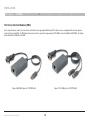
The Server Interface Modules (SIMs)
Each computer/server is directly connected to the Switch via the appropriate SIM using CAT5 cables in a star configuration. No external power is
needed at the remote SIMs. The SIMs draw their power from the computer’s keyboard port (PS/2 SIM) or from the USB port (USB SIM). The figures
below illustrate the SIM PS/2 and USB.
Figure 7 PS/2 SIM (part no. F1DP101A-AP)
Figure 6 USB SIM2 (part no. F1DP101A-AU)
OmniView® SMB CAT5 216/232 Switch
10
INSTALLATION
Table of Contents
sections
1
2
3
Connecting a PS/2 SIM
Power down the server
2.
Connect the mouse connector to the computer’s mouse port.
3.
Connect the keyboard connector to the computer’s keyboard port.
4.
Connect the video connector to the computer’s VGA port.
5.
The USB SIM supports Windows 2000 and later, Sun, SGI, and all
modern Linux distributions. The connections for USB SIM are exactly
the same. Figure 9 illustrates the USB SIM and its connections.
To connect the USB SIM:
Power on the server.
1.
Connect the video connector to the server’s VGA port.
2.
Connect the USB connector to the server’s USB port.
SIM PS/2
SIM USB
Figure 9 USB SIM
Figure 8 PS/2 SIM connections
OmniView® SMB CAT5 216/232 Switch
5
Connecting a USB SIM
Figure 8 illustrates the PS/2 SIM connections.
1.
4
11
INSTALLATION
Table of Contents
sections
1
2
3
4
5
Connecting to the network
Connecting the power supply
Connect the network cable to the LAN port of the Switch. This must be
done before powering on the Switch.
1.
Using the power cord provided, connect the Switch to a socket
outlet with a grounding connection. Only use the power cord
supplied with the unit.
Connecting the CAT5 cables
2.
Power on the Switch. Allow approximately 45 seconds for boot up.
1.
Connect one connector to the SIM’s RJ45 port.
2.
Connect the other connector to an available server port on
the Switch.
3.
Follow the steps above for each computer.
Connecting the local console
To operate the system locally, connect a local console to the Switch:
1.
Connect the monitor’s cable to the Switch’s console monitor port.
2.
Connect the keyboard’s cable to the Switch‘s console
keyboard port.
3.
Connect the mouse’s connector to the Switch’s console
mouse port.
OmniView® SMB CAT5 216/232 Switch
12
INSTALLATION
Table of Contents
sections
1
2
3
Setting the IP Address
2.
4
5
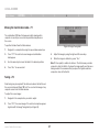
Press “F2”. The Settings window appears (see Figure 11).
By default, the Switch boots with an automatically assigned IP address
from a DHCP (Dynamic Host Configuration Protocol) server on the
network. The DHCP server provides a valid IP address, gateway
address, and subnet mask.
You can identify the IP address from the OSD at the local position. You
can set the IP address locally via the OSD where there is no DHCP
server as follows:
1.
From the local keyboard, press “Scroll Lock”. The OSD Main
window appears (see Figure 10).
Figure 11 Settings window
In the Settings window, navigate downward using the Tab key. At the
bottom of the window, press “Tab” to go to the top of the window.
Change settings by typing in the selected area or by pressing the space
bar—whichever is relevant.
Figure 10 OSD Main window
OmniView® SMB CAT5 216/232 Switch
13
INSTALLATION
Table of Contents
sections
1
2
3
Changing the network parameters
Enable DHCP – When a DHCP server is active on the same network to
which the Switch is connected, DHCP provides automatic IP assignment.
When DHCP is disabled (Recommended) – You can assign a fixed IP
address to the Switch.
Consult your network administrator regarding the use of the DHCP.
When DHCP is disabled, enter the IP Address, Subnet Mask, and
Gateway as given by your network administrator.
Once the IP address is satisfactory, log in to the web interface to
complete the configuration, as explained in the next section.
(Network parameters can also be changed from the remote GUI as
explained on page 17).
OmniView® SMB CAT5 216/232 Switch
14
4
5
WEB INTERFACE
Table of Contents
sections
1
2
3
4
5
Logging In to the Web Interface
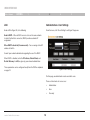
SSL certificate notes
Client computer operating system. Windows 2000 or higher, with
Internet Explorer 6.0 or later version. 128-bit encryption support
is required.
When first connecting, two browser security warnings appear. Click
“Yes” to proceed.
The first warning disappears upon the first Switch client installation,
when Belkin’s root certificate is installed.
Windows Vista Note! To log in to the web configuration interface with
Windows Vista, run Internet Explorer as “administrator.” To do this,
right-click the Internet Explorer icon on the task bar and select “Run” as
“administrator.” See figure below.
On first connection, install the Belkin certificate and ActiveX control. You
must be logged in as an administrator on your computer to install the
ActiveX control. Once the ActiveX control is installed, all types of users
can log in.
Figure 12 Select Run as administrator
OmniView® SMB CAT5 216/232 Switch
15
WEB INTERFACE
Table of Contents
sections
1
2
3
4
5
Logging in
To complete the initial setup via the web configuration interface:
1.
Open your web browser (Internet Explorer version 6.0 or higher).
2.
Type the Switch’s system IP address—http or https://IP address/ and press “Enter”. The login page appears (see Figure 13).
Figure 14 Targets page
Columns:
Server Name – The server name can be changed in the configuration
settings to give the server an identifiable name.
Figure 13 Login page
3.
Type the default administrator user name (admin) and password
(SMBremote) (case-sensitive).
4.
Press “Enter”. The web interface opens at the Targets page (see
Figure 14).
5.
Bookmark the page for easy reference.
OmniView® SMB CAT5 216/232 Switch
Port Status – Port status can be on, off, or busy (i.e., another user is
accessing the server).
Current User – The current user (if any) who is accessing the target.
16
WEB INTERFACE
Table of Contents
sections
1
2
3
4
5
Configuring the System
Network > Configuration
Configuring the system includes setting network parameters, user and
security settings, and maintenance.
Consult your network administrator for the network settings if necessary.
Device Name – Type a name for the Switch.
From the menu, click “Configuration”. The “Network > Configuration”
page, including the Configuration menu, appears:
TCP Ports – Choose any three TCP ports between ports 800 to 65535.
When the Switch is a standalone system, the ports do not have to be
consecutive. (The port numbers can be changed from Central Access
Appliance, if needed.)
Notes
The firewall or router security access list must enable inbound
communication through the selected TCP ports for the Switch’s
IP address.
For client computer access from a secured LAN, the selected ports
should be open for outbound communication.
Figure 15 Network > Configuration page
OmniView® SMB CAT5 216/232 Switch
17
WEB INTERFACE
Table of Contents
sections
1
2
3
4
5
LAN
Administration > User Settings
Under LAN in Figure 14, is the following:
From the menu, click “User Settings” and Figure 16 appears.
Enable DHCP – When a DHCP server is active on the same network
to which the Switch is connected, DHCP provides automatic IP
assignment.
When DHCP is disabled (Recommended) – You can assign a fixed IP
address to Switch.
Consult your network administrator regarding the use of the DHCP.
When DHCP is disabled, enter the IP Address, Subnet Mask, and
Default Gateway for LAN, as given by your network administrator.
These parameters can be configured locally from the OSD as explained
on page 14.
Figure 16 User Settings
On this page, an administrator creates and edits users.
There are three levels of user access:
OmniView® SMB CAT5 216/232 Switch
18
•
Administrator
•
User
•
View only
WEB INTERFACE
Table of Contents
sections
1
2
3
5
Adding a user
Administrator
An administrator has unrestricted access to all windows and settings
and can “take over” any active session. An administrator can change the
name and password and target server permissions of all users.
To add a user:
User
A user can access/control permitted target servers, but cannot use the
advanced mouse settings.
1.
Click
and type a name and a password. The password
must be at least six characters (letters or numbers), and must not
include the user name, even if other characters are added.
Note! The following “special” characters: &, <, >, ”, {, and } cannot
be used for either the user name or password.
Depending on the security level chosen, the user name and
password parameters are different. See the “Security > Settings”
section on page 21.
2.
Select the permission type from the “Permission” box.
3.
Click
and the user will appear in the list of users. The
Permission column shows the user level (Administrator, User, and
View Only). The Status column shows whether the user is blocked
or unblocked (explained in the “Blocking a user” section).
A user has no access to the web-configuration interface.
View only
“View only” can view the screen of the currently accessed target server
without keyboard and mouse control. A “view only” indicator appears on
the viewer’s local mouse pointer.
OmniView® SMB CAT5 216/232 Switch
4
19
WEB INTERFACE
sections
Table of Contents
1
2
3
4
5
Editing a user
Administration > Server Name Edit
To edit a user:
Give the servers connected to the Switch unique names, so that users
accessing the system can identify the servers easily.
1.
Select the user from the user drop-down menu.
To do so:
2.
You can now change all the parameters—user name, permission,
password, and blocking status (see the “Blocking a user” section).
1.
From the menu, click “Server Name Edit”. The Switch Configuration
window appears (see Figure 17).
3.
Click
2.
In the “Server Name” section, change the name of the connected
servers by selecting the server name and typing a new name. Click
to save changes.
. The changes are saved.
Deleting a user
To delete a user:
1.
Select the user from the list.
2.
Click
.
3.
Click
to save any changes.
Blocking a user
An alternative to deleting a user entry completely is blocking a user.
This means that the user’s name and password is stored, but the user is
unable to access the system. Check “Block” to block a user, and then
click
to save any changes. Uncheck “Block” and click
to
allow the user access.
OmniView® SMB CAT5 216/232 Switch
Figure 17 Switch Configuration
20
WEB INTERFACE
Table of Contents
sections
1
2
3
4
5
Administration > Server Access List
3.
Check the target servers the user can access (according to his or
her access permissions). To select all target servers, click
.
By default, access is allowed to all servers for administrators. For other
users, define the access rights of each user separately.
4.
Click
To do so:
5.
Repeat the steps above for additional users.
1.
From the menu, click “Server Access List”. The Access List
Configuration window will appear (see Figure 18).
to save the selection.
Security > Settings
Configure the security features, such as Account Blocking, Password
Policy, and Idle Timeout, as explained below.
From the Security section, click “Settings”. The “Security > Settings”
page appears (see Figure 19).
Figure 18 Server Access List Configuration
2.
Select a user from the user drop-down menu.
OmniView® SMB CAT5 216/232 Switch
Figure 19 Security Settings
21
WEB INTERFACE
Table of Contents
sections
1
2
3
4
Security Settings fields:
Security > SSL Certificate
Account Blocking – Decide on the number of attempts to log in with a
wrong user name or password, after which there is a time lock or a
total block.
You can install an SSL certificate.
To do so:
Password Policy
From the menu, select “SSL Certificate”. The Install SSL Certificate page
appears (see Figure 20).
For local and remote users, you have the option of a standard or high
security level of password. The table below shows the parameters of the
two options.
Standard
security policy
High security policy
6 characters or
more
8 characters or more, must include at least 1
digit and 1 uppercase letter, and 1 “special”
character as follows: !@#$%^*()_-+=[]’:;?/
Must not include
the user name
Must not include the user name
5
Figure 20 Install SSL Certificate page
Check the box to enable the high security password policy. If left
unchecked, the standard security policy applies.
OSD password enabled – For the local user, access to the OSD can
be password enabled or disabled (default), with the option of a standard
or high security level of password as explained above. Select the check
box to enable password.
Certificate File – Browse to locate the “cer” file (.ssl format).
Note! The user access permissions are the same whether access is
done locally or remotely.
Click
Private Key File – Browse to locate the “private key” file (.pem format).
Key Password – Type the key password.
Idle Timeout – Select the timeout inactivity period after which the user is
disconnected from the system. Choose “No Timeout” to disable timeout.
Click
to save any security changes.
OmniView® SMB CAT5 216/232 Switch
22
. The certificate installs. The device restarts automatically.
WEB INTERFACE
Table of Contents
sections
1
2
3
4
5
Maintenance > Switch Upgrade
Maintenance > SIM Upgrade
Upgrade the Switch firmware to take advantage of new features.
Download the firmware from the support section of Belkin’s website at
www.belkin.com/support. Save the firmware file on the client computer.
Upgrade the SIM firmware to take advantage of new features. Download
the firmware from the support section of the Belkin website at www.
belkin.com/support. Save the firmware file on the client computer.
From the menu, select “Switch Upgrade”. The Upgrade window will
appear, showing the current firmware version (see Figure 21).
1.
From the menu, select “SIM Upgrade”. The Upgrade window
should appear, showing the current firmware version (see
Figure 22).
2.
Select the servers connected to the SIM you wish to upgrade.
3.
Verify the current version of the firmware by clicking
Figure 21 Firmware Upgrade
1.
4.
Locate and upload the firmware file.
5.
Press
and the firmware upgrades.
Locate and upload the firmware file.
2.
Verify the current and uploaded version of the firmware.
3.
Click
to begin the upgrade process. The unit will reboot
automatically. You should see the Login page reappear after about
two minutes.
Note!
Depending on the type of firmware upgrade type, the following settings
may be erased: user settings, server names, and mouse and video
adjustments. For more information, refer to the firmware release notes.
The network settings will remain intact.
OmniView® SMB CAT5 216/232 Switch
Figure 22 SIM Upgrade
23
.
WEB INTERFACE
sections
Table of Contents
1
2
3
4
5
Restore Factory Settings
Set Time and Date
You can restore the Switch to the factory settings. This restores the
original Switch parameters, resetting all the information added by
the administrators, including network settings*, servers, users, and
passwords, etc.
The time and date set feature is used when recording log events. To set
the time and date:
From the menu, select “Time & Date” and Figure 24 appears.
*You have the option to preserve network settings, explained below.
Warning! Once reset the data cannot be retrieved.
To restore factory settings:
1.
From the menu, select “Restore Factory Settings”. The Restore
Factory Settings page appears (see Figure 23).
Figure 24 Set Time & Date
Type the appropriate parameters.
Figure 23 Restore factory settings
2.
Check the box if you want to preserve network settings.
3.
Click
.
OmniView® SMB CAT5 216/232 Switch
24
WEB INTERFACE
Table of Contents
sections
1
2
3
4
5
Back Up and Restore
Saving Changes and Logging Out
You can back up all configuration data to restore it at a later date. To
do so:
To save any configuration changes, click the relevant button on the
current page. This could be
or just
.
From the menu, select “Backup & Restore” and Figure 25 appears.
To restart the Switch, press
.
To exit the Configuration menu and close the session, click
.
Only one administrator can log in to the Configuration area at a time.
After the idle timeout (see the “Security > Settings” section on page 21),
the session terminates.
Figure 25 Backup & Restore
To back up the configuration data, click
to save the file.
To restore the configuration data, browse to locate the file and press
. The device restarts.
OmniView® SMB CAT5 216/232 Switch
25
LOCAL ACCESS
Table of Contents
sections
1
2
3
4
5
This section explains how to operate the Switch locally via the OSD.
Navigating the OSD Main window
The OSD
To navigate up and down, use the up and down arrow keys.
To exit the OSD, press “Esc”.
To display the OSD:
1.
Selecting a computer
From the local keyboard, press the left “Scroll Lock” key twice.
The OSD Main window appears (see Figure 28). The “Pwr” column
indicates the server is powered on.
To select a computer:
Figure 28 OSD Main window
OmniView® SMB CAT5 216/232 Switch
26
1.
Navigate to the desired computer line.
Or, type the 2-digit port number of the desired computer.
2.
Press “Enter”. The selected computer is accessed. A confirmation
label appears showing which computer is accessed.
LOCAL ACCESS
Table of Contents
sections
1
2
3
4
5
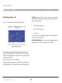
Moving the Confirmation label – F1
The confirmation OSD label that appears briefly showing which
computer is currently accessed can be positioned anywhere on
the screen.
To position the label from the Main window:
Figure 29 Image Tuning label
1.
Navigate to a computer line using the up and down arrow keys.
2.
Press “F1”. The selected screen image and confirmation
label appear.
3.
Adjust the image by using the right and left arrow keys.
4.
When the image is satisfactory, press “Esc”.
3.
Use the arrow keys to move the label to the desired position.
4.
Press “Esc” to save and exit.
Note! Picture quality is relative to distance. The farther away a remote
computer is from the Switch, the lower the image quality, and the more
tuning needed. We recommend that you place the higher-resolution
computers closer to the Switch.
Tuning – F5
Video tuning may be required if the distance between the Switch and
the server is between 50 and 100 feet. You can tune the image of any
computer screen from the Main window.
To adjust the screen image:
1.
Navigate to the computer line you wish to adjust.
2.
Press “F5”. The screen image of the selected computer appears
together with the Image Tuning label (see Figure 29).
OmniView® SMB CAT5 216/232 Switch
27
LOCAL ACCESS
Table of Contents
sections
1
2
3
The Settings window – F2
4
5
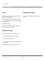
HOT KEY – Pressing “Scroll Lock” twice in quick succession will make
the OSD appear. You can replace “Scroll Lock” with any of the other
hot-key options following:
Press “F2”. The Settings window appears (see Figure 30).
•
Ctrl, Ctrl (left Ctrl key only)
•
Ctrl, F11 (left Ctrl key only)
•
Print Screen
Press the space bar to toggle between options. To display the OSD in
the future, press the new hot key.
KEYBOARD LANGUAGE – Press the space bar to toggle between the
language options. It can be changed to French or German.
Figure 30 Settings window
In the Settings window, navigate downward using the “Tab” key. At
the bottom of the window, press “Tab” to go to the top of the window.
Change settings by typing in the selected area or by pressing the space
bar, whichever is relevant.
From this window, you can do the following:
Changing the network parameters from the OSD is explained with the
initial configuration in the “Setting the IP Address” section on page 13.
OmniView® SMB CAT5 216/232 Switch
28
LOCAL ACCESS
Table of Contents
sections
1
2
3
4
5
DDC – F10
Saving changes to the settings
Display Data Channel (DDC) is a VESA standard for communication
between a monitor and a video adapter.
To save changes to the settings and return to the Main window,
press “Esc”.
From the Settings window, input the DDC information of the monitor
connected to the Switch into the memories of all connected SIMs when
first installing the system.
To input the DDC information:
Press “F10”. “Please wait” flashes a few times and disappears. The
monitor’s DDC information is sent to all SIMs.
Updating the DDC information
Update the DDC information in any of the following circumstances:
•
When replacing the monitor connected to the Switch
•
When adding a new SIM to the system
•
When reconnecting an existing SIM that was temporarily used in a
different system
To update the DDC information, repeat the steps as set out above.
OmniView® SMB CAT5 216/232 Switch
29
ADDITIONAL INFORMATION
Table of Contents
sections
1
2
3
4
5
Technical Specifications
Operating Systems
Resolution
Target Server
PS/2 SIM
USB SIM
VGA - HDD15
VGA - HDD15
KM - MiniDIN6
KM - USB
System - RJ45
System - RJ45
Power
From keyboard port
From USB port
Product Weight
100g/0.20 lbs.
Ethernet – RJ45 – 10/100bps auto-sensing
Shipping Weight
172g/0.38 lbs.
Local KVM Connection – Screen HDD15, Keyboard/
Mouse – 2 USB
Dimensions
65 x 25 x 25mm/0.21 x 0.08 x 0.08 in.
Windows, Novell, Linux, Sun Solaris
Target Server
Distance from Switch to SIMs
Up to 30m/99 ft.
Security
128-bit SSL encryption
Connections
Connections
Up to 1600x1200@85Hz
Servers – RJ45
Weight
2.343kg./5.165 lbs.
Dimensions (H x D x W)
44 x 270 x 431mm/1.7 x 10.6 x 17 in.
Power Input
100–240VAC, 0.8A, 50/60Hz
Operating Temperature
0° C to 40° C/32° F to 104° F
Storage Temperature
-40° C to 70° C/-40° F to 158° F
Humidity
80% non-condensing relative humidity
OmniView® SMB CAT5 216/232 Switch
30
additional information
Table of Contents
sections
1
2
3
4
5
Safety
Product Registration
This device contains no serviceable parts. Any servicing of the device
must be performed by Belkin International, Inc.
You may register your product online by going to
https://www.belkin.com/registration/.
User Manual Feedback
This will assist Belkin in contacting you regarding important information
regarding the use of your product.
Your feedback is very important to help us improve our documentation.
Please email any comments to: [email protected].
Please include the following information: Manual name, part number,
and P number.
OmniView® SMB CAT5 216/232 Switch
31
additional information
Table of Contents
sections
1
2
3
4
5
Information
FCC Statement
DECLARATION OF CONFORMITY WITH FCC RULES FOR ELECTROMAGNETIC COMPATIBILITY
CE Declaration of Conformity
We, Belkin International, Inc., of 501 West Walnut Street, Compton, CA
90220, declare under our sole responsibility that the products:
We, Belkin International, Inc., declare under our sole responsibility that
the products F1DP216A, F1DP232A, to which this declaration relates,
are in conformity with Emissions Standard EN55022 and with Immunity
Standard EN55024, LVP EN61000-3-2, and EN61000-3-3.
F1DP216A, F1DP232A
to which this declaration relates:
This equipment has been tested and found to comply with the limits
for a Class A digital device, pursuant to Part 15 of the FCC Rules.
These limits are designed to provide reasonable protection against
harmful interference when the equipment is operated in a commercial
environment. This equipment generates, uses, and can radiate radio
frequency energy and, if not installed and used in accordance with
the instruction manual, may cause harmful interference to radio
communications. Operation of this equipment in a residential area
is likely to cause harmful interference in which case the user will be
required to correct the interference at his or her own expense.
OmniView® SMB CAT5 216/232 Switch
ICES
This Class A digital apparatus complies with Canadian ICES-003. Cet
appareil numérique de la classe A est conforme á la norme NMB-003 du
Canada.
32
Additional information
Table of Contents
sections
1
2
3
4
5
Belkin International, Inc., Limited 2-Year Product Warranty
What this warranty covers.
and tear, erosion, depletion, obsolescence, abuse, damage due to low
voltage disturbances (i.e., brownouts or sags), non-authorized program,
or system-equipment modification or alteration.
Belkin International, Inc. (“Belkin”) warrants to the original purchaser of
this Belkin product that the product shall be free of defects in design,
assembly, material, or workmanship.
How to get service.
What the period of coverage is.
To get service for your Belkin product you must take the following steps:
Belkin warrants the Belkin product for two years.
What will we do to correct problems?
1.
Contact Belkin International, Inc., at 501 W. Walnut St., Compton
CA 90220, Attn: Customer Service, or call (800)-223-5546, within
15 days of the Occurrence. Be prepared to provide the following
information:
a. The part number of the Belkin product.
b. Where you purchased the product.
c. When you purchased the product.
d. Copy of original receipt.
2.
Your Belkin Customer Service Representative will then instruct
you on how to forward your receipt and Belkin product and how to
proceed with your claim.
Product Warranty.
Belkin will repair or replace, at its option, any defective product free of
charge (except for shipping charges for the product). Belkin reserves the
right to discontinue any of its products without notice, and disclaims any
limited warranty to repair or replace any such discontinued products.
In the event that Belkin is unable to repair or replace the product (for
example, because it has been discontinued), Belkin will offer either a
refund or a credit toward the purchase of another product from Belkin.
com in an amount equal to the purchase price of the product as
evidenced on the original purchase receipt as discounted by its
natural use.
What is not covered by this warranty?
All above warranties are null and void if the Belkin product is not
provided to Belkin for inspection upon Belkin’s request at the sole
expense of the purchaser, or if Belkin determines that the Belkin product
has been improperly installed, altered in any way, or tampered with.
The Belkin Product Warranty does not protect against acts of God such
as flood, lightning, earthquake, war, vandalism, theft, normal-use wear
OmniView® SMB CAT5 216/232 Switch
33
Additional information
Table of Contents
sections
1
2
3
Belkin reserves the right to review the damaged Belkin product. All
costs of shipping the Belkin product to Belkin for inspection shall be
borne solely by the purchaser. If Belkin determines, in its sole discretion,
that it is impractical to ship the damaged equipment to Belkin, Belkin
may designate, in its sole discretion, an equipment repair facility to
inspect and estimate the cost to repair such equipment. The cost, if any,
of shipping the equipment to and from such repair facility and of such
estimate shall be borne solely by the purchaser. Damaged equipment
must remain available for inspection until the claim is finalized.
Whenever claims are settled, Belkin reserves the right to be subrogated
under any existing insurance policies the purchaser may have.
5
Some states do not allow limitations on how long an implied warranty
lasts, so the above limitations may not apply to you.
IN NO EVENT SHALL BELKIN BE LIABLE FOR INCIDENTAL, SPECIAL,
DIRECT, INDIRECT, CONSEQUENTIAL OR MULTIPLE DAMAGES SUCH
AS, BUT NOT LIMITED TO, LOST BUSINESS OR PROFITS ARISING
OUT OF THE SALE OR USE OF ANY BELKIN PRODUCT, EVEN IF
ADVISED OF THE POSSIBILITY OF SUCH DAMAGES.
This warranty gives you specific legal rights, and you may also have
other rights, which may vary from state to state. Some states do not
allow the exclusion or limitation of incidental, consequential, or other
damages, so the above limitations may not apply to you.
How state law relates to the warranty.
THIS WARRANTY CONTAINS THE SOLE WARRANTY OF BELKIN.
THERE ARE NO OTHER WARRANTIES, EXPRESSED OR, EXCEPT AS
REQUIRED BY LAW, IMPLIED, INCLUDING THE IMPLIED WARRANTY
OR CONDITION OF QUALITY, MERCHANTABILITY OR FITNESS FOR A
PARTICULAR PURPOSE, AND SUCH IMPLIED WARRANTIES, IF ANY,
ARE LIMITED IN DURATION TO THE TERM OF THIS WARRANTY.
OmniView® SMB CAT5 216/232 Switch
4
34
Belkin Tech Support
US: 800-282-2355
310-898-1100, ext. 2263
UK: 0845 607 77 87
Australia: 1800 235 546
New Zealand: 0800 235 546
Singapore: 65 64857620
Europe: www.belkin.com/support
Belkin International, Inc.
501 West Walnut Street
Los Angeles, CA 90220, USA
310-898-1100
310-898-1111 fax
Belkin Ltd.
Express Business Park, Shipton Way
Rushden, NN10 6GL
United Kingdom
+44 (0) 1933 35 2000
+44 (0) 1933 31 2000 fax
Belkin Ltd.
4 Pioneer Avenue
Tuggerah Business Park
Tuggerah, NSW 2259, Australia
+61 (0) 2 4350 4600
+61 (0) 2 4350 4700 fax
Belkin B.V.
Boeing Avenue 333
1119 PH Schiphol-Rijk
The Netherlands
+31 (0) 20 654 7300
+31 (0) 20 654 7349 fax
© 2009 Belkin International, Inc. All rights reserved. All trade names are registered trademarks of respective
manufacturers listed. Windows, Windows Vista, Microsoft, NT, Internet Explorer, and ActiveX are either
registered trademarks or trademarks of Microsoft Corporation in the United States and/or other countries.