1
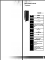
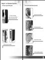
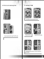
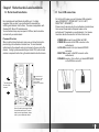
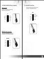
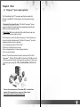
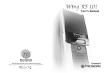
VD2000BNS User Manual C 2006 Thermaltake Technology Co.,Ltd. All Rights Reserved. Contents Chapter l Product Introduction 1.1 Specification 2 Chapter 2 Case Mechanical Operation 2.1 How to open the side panel 3 2.2 Front fan Installation (Optional) 4 2.3 Installing 5.25" device 5 2.4 PCI slot tool-free function operation 7 2.5 Installing 3.5" HDD 8 2.6 Installing 3.5" device 9 Chapter 3 Motherboard & Leads Installation 3.1 Motherboard installation 11 3.2 Case LED connections 12 3.3 USB2.0 & IEEE1394 Firewire connection 13 3.4 Ear & MIC connections 14 Chapter 4 Other 4.1 Purepower TM power supply(optional) 15 Chapter l Product Introduction 1.1 Specification VD2000BNS >>> Model VD2000BNS Case Type Middle Tower Net Weight 5.68 kg Dimension (H*W*D) 420 x 190 x 480 mm Front (Intake) : 120 x 120 x 25 mm (optional) Cooling System Rear (Exhaust) : 120 x 120 x 25 mm, 1300rpm, 17dBA Drive Bays - Accessible - Hidden 10 4 x 5.25 5.25" , 2 x 3.5" 3.5 4 x 3.5" 3.5 Material SECC Japanese steel Color Black Expansion Slots 7 Motherboards Micro ATX , Standard ATX § All mesh front panel design § Dual USB 2.0, IEEE 1394 Firewire, MIC & Speaker ports Features § Tool -free installation for all drive bays & add-on cards § High efficiency ventilation: 12cm silent fan in rear (front 12cm fan is optional) § Entirely filtered front panel design to prevent dust built up 1 2 Chapter2 Case Mechanical Operation 2.1 How to open the side panel 2.2 Front Fan Installation (Optional) Œ Remove the front panel first. u To remove the side panel, please remove upper and bottom screws on the back of the case. • Place the fan as shown. w Secure the fan by screws. v Pull the side panel to release it. x Front fan installation completed. 3 4 2.3 Installing 5.25" Device • Remove the 5.25" drive bay metal cover. Œ Remove the front panel. ‘ Place 5.25" device into the drive bay. • Remove the 5.25" drive bay cover with mesh and black sponge. ’ Put back the lock device and turn lock device clockwise to lock. Ž Turn lock device counterclockwise to unlock. • Remove lock device. “ 5.25" device installation complete. 5 6 2.4 PCI slot tool-free function operation 2.5 Installing 3.5" HDD u Turn lock device counter-clockwise to unlock. Œ Open the plastic clip then take off the PCI bracket. v Remove lock device. w Place HDD into the drive bay. x Put back the lock device and turn lock device clockwise to secure the HDD. 7 8 2.6 Installing 3.5" device Œ Remove the front panel. • Remove the 3.5" drive bay cover with mesh and black sponge. • Insert lock device and turn clockwise to secure the drive. ‘ 3.5" device installation complete. Ž Turn lock device counter-clockwise to unlock. • Remove lock device and insert drive from the front of the chassis. 9 10 Chapter3 Motherboard & Leads Installation 3.2 Case LED connections 3.1 Motherboard Installation Each motherboard has different standoff layout. It is highly suggested that you refer to your motherboard's manual when installing motherboard into the Case. The cases are applicable with Standard ATX, Micro ATX motherboards. Your motherboard may require a special I/O Panel, which should be included with your motherboard. Placement Direction: When installing the motherboard, make sure you follow the direction provided by your motherboard manufacturer. On most standard motherboards, the edge with external ports goes to the rear part of the chassis. It is highly recommended that you install CPU, heat sink and modular components before fixing the motherboard inside the chassis. On the front of the case, you can find some LEDs and switch leads (POWER SW*1, POWER LED*1, H.D.D. LED*1, RESET SW*1, SPEAKER*1). Please consult user manual of your motherboard manufacturer, then connect these leads to the panel header on the motherboard. These leads are usually labeled; if not, please trace them back to the case front to find out their source. - POWER LED connects to your M/B at the PLED - POWER SW connects to the PWR connector on the motherboard. - H.D.D LED connects to the 2-pin labeled HDD LED connector. - RESET SW connects to the RSW connector on the motherboard, - SPEAKER connector: find out the 4-pin labeled SPEAKER on the M/B then connect it. = the locations of the screw holes. Note these locations and place included standoffs on the chassis first. This side towards the rear of the chassis Above illustration is a sample of what the motherboard's layout. For more detail screw hole placement, please refer to your motherboard manual. 11 12 3.3 USB2.0 & IEEE1394 Firewire connection USB connection Please consult your motherboard manual to find out the section of "USB connection". 3.4 Ear & MIC connections Please consult your motherboard manual to find out the section of "front panel audio connector". AUDIO USB Vcc1 Data-1 Data+1 GND1 1 3 5 7 9 2 4 6 8 10 Vcc2 Data-2 Data+2 GND2 GND1 3 R-RET 5 KEY 7 L-RET 9 2 MIC-IN 4 MIC-POWER 6 R-OUT 10 L-OUT KEY IEEE1394 Firewire connection Please consult your motherboard manual to find out the section of "IEEE1394 Firewire connection". IEEEE1394 TPAVG TPBVP SHELL 1 3 5 7 9 2 4 6 8 10 TPA+ VG TPB+ VP KEY 13 14 Chapter4 Other TM 4.1 Purepower power supply (optional) The Thermaltake Silent TM Purepower specification meets Intel Pentium 4 and AMD K7; it offers plenty of functions, which mainly include: 1.Automatic Fan Speed Control: The Silent Purepower TM power supply can detect the inside heat and automatically adjust the fan speed to provide adequate airflow. 2.Ultra Silent:Ball bearing fans with high reliability and super low acoustic noise under all load condition. The functions can assure the Silent Purepower TM meet the balance in noise control and heat exhausted. The Silent PurepowerTM provides complete protection function as follow: 1.Over thermal protection at 100 oC-105 oC 2.Short circuit protection on all output. 3.Over voltage protection / Under voltage protection. 4.Over current protection. Besides, Thermaltake enables the quality assurance of the Silent Purepower TM: 100% Hi-POT and ATE Function Test, 100% Burn-In and AC Input cycled on/off under high temperature condition. Furthermore, it has been approved by UL, CSA, TUV, VDE, NODIC, CB, FCC, CE, CNS. There are three main products of Thermaltake PSU, it is divided into standard, VR and specialty power supply unit. Please refer to http://www.thermaltake.com/purepower/main.htm 15 16