1
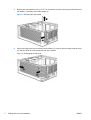
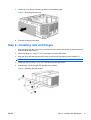
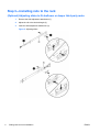
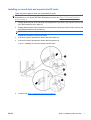
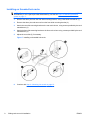
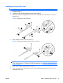
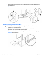
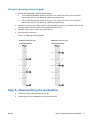
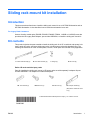
Sliding rack-mount kit installation
Introduction
This document describes how to install the sliding rack mount kit on an HP Z600 Workstation and an
HP Z800 Workstation. It also describes how to install the workstation into a rack.
For Legacy Rack Customers:
Owners of earlier model racks (E3660B, E3661B, E3662B, E7590A, J1450B or J1487A/B) must also
purchase the HP Legacy Rack Adapter, part number WD587AA, to install the sliding rack mount kit.
Kit contents
This product includes the parts needed to install the sliding rack kit in HP round hole and square hole
racks, earlier HP racks, and some third-party racks, including some racks with threaded holes. The
following list describes all of the included parts; however, not all parts are used with every application.
A. Outer slide assembly (2)
B. Inner slide assembly (2)
C. Flange (2)
D. M4 screw (8)
Earlier HP racks and third party racks
Parts for installing the sliding rack mount in HP legacy racks are sold separately in adapter kit part
number WD587AA. This adapter kit includes these parts:
AA. Front bracket (2)
BB. M5 screw (4)
CC. M6 screw (2)
DD. Adapter bracket (2)
(Required for earlier HP racks
only.)
© 2009 Hewlett-Packard Development Company, L.P. Printed in the U.S.
ENWW
Introduction
1
Warnings and cautions
WARNING!
Any surface or area of the equipment marked with this symbol indicates the presence
of an electrical shock hazard. To reduce the risk of injury from electrical shock, do not open any enclosed
area marked with this symbol.
WARNING! To reduce the risk of electric shock or damage to your equipment:
— Do not disable the power cord grounding plug. The grounding plug is an important safety feature.
— Plug the power cord in a grounded (earthed) outlet that is easily accessible at all times.
— Disconnect power from the equipment by unplugging the power cord from the electrical outlet.
WARNING!
Any surface or area of the equipment marked with this symbol indicates the presence
of a hot surface or hot component. If this surface is contacted, the potential for injury exists. To reduce
the risk of injury from a hot component, enable the surface to cool before touching.
WARNING! If a product is shipped in packaging marked with this symbol,
, the product must always
be lifted by two persons to avoid personal injury due to product weight.
WARNING! To reduce the risk of serious injury, read the Safety & Comfort Guide. It describes proper
workstation setup, posture, health, and work habits for computer users, and provides important electrical
and mechanical safety information. This guide is located at http://www.hp.com/ergo and on the
documentation CD (if one is included with the product).
CAUTION: Static electricity can damage the electronic components of the workstation. Before
beginning these procedures, be sure you discharge static electricity by briefly touching a grounded metal
object.
CAUTION: To prevent damage to the workstation, observe the following Electrostatic Discharge
(ESD) precautions while performing the system parts removal and replacement procedures:
— Work on a static-free mat.
— Wear a static strap to ensure that any accumulated electrostatic charge is discharged from your body
to the ground.
— Create a common ground for the equipment you are working on by connecting the static-free mat,
static strap, and peripheral units to that piece of equipment.
NOTE: HP accessories are for use in HP Workstation products. They have been extensively tested
for reliability and are manufactured to high quality standards.
2
Sliding rack-mount kit installation
ENWW
Tools required
Round hole and square hole racks
●
T-15 Torx screwdriver
Threaded hole racks
●
T-15 Torx screwdriver
●
Flat head screwdriver
●
Cross-tip screwdriver
For earlier HP racks including E3660B, E3661B, E3662B, J1450B, J1487A,
J1487B
●
T-15 Torx screwdriver
●
T-25 Torx screwdriver
●
M10 socket wrench
Step 1—Preparing the workstation
NOTE: All illustrations are examples only. Workstation models vary. For product-specific information,
see the service guide for your HP workstation at http://www.hp.com/support/workstation_manuals
before beginning installation.
To prepare the workstation for component installation:
ENWW
1.
Power down the workstation and all external devices.
2.
Disconnect the workstation power cord.
3.
Disconnect all connections to external devices.
4.
Remove the side access panel.
Tools required
3
5.
Remove the rear handle by using a T-15 Torx screwdriver to remove the long screw that secures
the handle (1), and then remove the handle (2).
Figure 1 Removing the rear handle
6.
Lift the rear edge of the top cover at the center detente (1), press on the front edge of the top cover
(2), and then slide the cover toward the rear of the system.
Figure 2 Disengaging the top cover
4
Sliding rack-mount kit installation
ENWW
7.
Lift the top cover from the chassis as shown in the following figure.
Figure 3 Removing the top cover
8.
Reinstall the side access panel.
Step 2—Installing rails and flanges
1.
Align the flange with the screw holes on the left side of the chassis (the bottom of chassis becomes
the left side for mounting) (1).
2.
Attach the flange (2), using a T-15 Torx screwdriver and two M4 screws.
3.
Align the inner slide with the two screw holes on the left side (the bottom) of the chassis (3).
NOTE:
The front inner slide is stamped “FRONT.”
4.
Attach the slide (4) using a T-15 Torx screw driver and two M4 screws.
5.
Repeat steps 1–4 for the right side (the top) of the chassis.
Figure 4 Installing rails and flanges
ENWW
Step 2—Installing rails and flanges
5
Step 3—Installing rails to the rack
(Optional) Adjusting slides to fit shallower or deeper third-party racks
1.
Remove the slide adjustment attachment (1).
2.
Adjust the rail to the desired length (2).
3.
Insert the slide adjustment attachment (3).
Figure 5 Adjusting slides
6
Sliding rack-mount kit installation
ENWW
Installing on round hole and square hole HP racks
These instructions apply to racks such as standard HP racks.
NOTE: To determine the appropriate alignment for a workstation that requires a 4U space (HP Z600
Workstations) or a 5U space (HP Z800 Workstations), see the two Figure 12 Mounting reference
guides on page 11.
1.
Engage the three pins on the rear slide mounting bracket in the holes in the rear rack column, and
then slide forward to lock in place (1).
2.
Engage the three pins on the front slide mounting bracket in the holes in the front rack column, and
then slide backward to lock in place (2).
NOTE:
The slide telescopes to accomplish this task.
Repeat this procedure for the second slide.
3.
If the slide must be repositioned, release the rear bracket (3).
4.
If the slide must be repositioned, release the front bracket (4).
Figure 6 Installing on round and square hole HP racks
5.
ENWW
Continue with Step 4—Mounting into a rack on page 10.
Step 3—Installing rails to the rack
7
Installing on threaded hole racks
NOTE: To determine the appropriate alignment for a workstation that requires a 4U space (HP Z600
Workstations) or a 5U space (HP Z800 Workstations), see the two Figure 12 Mounting reference
guides on page 11.
1.
Remove the three pins from the rear slide mounting bracket, using a flat blade screwdriver (1).
2.
Remove the three pins and two nuts from the front slide mounting bracket (2).
3.
Attach the rear slide mounting bracket to the rear rack column, using screws provided by the rack
manufacturer (3).
4.
Attach the front slide mounting bracket to the front rack column using, screws provided by the rack
manufacturer (4).
5.
Adjust the rear slide (5) if necessary.
Figure 7 Installing on threaded hole racks
6.
8
Continue with Step 4—Mounting into a rack on page 10.
Sliding rack-mount kit installation
ENWW
Installing on earlier HP racks
NOTE:
The parts for this procedure are available separately in adapter kit number WD587AA.
1.
Extend the rails (1).
2.
Remove the rear mounting brackets from the outer slides (2).
3.
Remove the front mounting brackets from the outer slides (3). Save the bracket nuts for use in
Steps 6 and 7.
Figure 8 Installing on earlier HP racks
4.
Attach adapter bracket to the outer slides (4).
Figure 9 Attaching the adapter bracket to the outer slides
NOTE: To determine the appropriate alignment for a workstation which requires a 4U space
(Z600 Workstations) or a 5U space (HP Z800 Workstations), see Figure 12 Mounting reference
guides on page 11.
ENWW
5.
Attach the front bracket with two M5 screws (5).
6.
Attach the slide to the inside rear of the rack, using an M6 flathead screw and one of the nuts
removed in Step 3 (6).
Step 3—Installing rails to the rack
9
7.
Attach the slide to the front of the rack using the M6 screw mounted in the slide and the remaining
nut from Step 3 (7).
Figure 10 Attaching the brackets
Step 4—Mounting into a rack
WARNING! Two people are necessary to properly align and install the workstation and rails.
1.
Insert the inner rails into the outer rails.
2.
Push the workstation to slide it completely into the rack. If the rails are locked, disengage them by
pressing the green lever found on the side of the outer rail.
3.
Secure the workstation into the rack by tightening the thumb screws found on the mounting flanges.
Figure 11 Mounting into a rack
10
Sliding rack-mount kit installation
ENWW
Using the mounting reference guide
1.
Choose the appropriate mounting reference guide.
●
The HP Z600 Workstation requires a 4U space. The center of the rails (1) is 2U from the
bottom of the rack (or from the top of a previously-installed unit).
●
The HP Z800 Workstation requires a 5U space. The center of the rails (1) is 3U from the
bottom of the rack (or from the top of a previously-installed unit).
2.
Measure from point (2), the lower surface of the workstation to point (1), the location of the center
line of the slides. The top surface of the workstation is at point (3).
3.
Mark the location for the center line of the slides (1).
4.
Mount the rails on the rack.
Figure 12 Mounting reference guides
4U Mounting reference guide
5U Mounting reference guide
HP Z600 Workstations
HP Z800 Workstations
Step 5—Reassembling the workstation
ENWW
1.
Reconnect external devices and power cords.
2.
Restore power to the workstation and all external devices.
Step 5—Reassembling the workstation
11
Japanese 日本語
This document is available in Japanese. See http://www.hp.com/support/workstation_manuals, then
select your workstation product and select Japanese from the drop down Manual Language menu.
このドキュメントは日本語版が用意されています。http://www.hp.com/support/workstation_manuals
にアクセスし、ご使用のワークステーション製品を選択し、Manual Language ドロップダウン メニ
ューから Japanese を選択してください。
12
Sliding rack-mount kit installation
ENWW