1
CAM6.6T-S1 System
6-Zone, 6-Source
AM/FM Receiver and
UNO-S1 Smart Keypads
INSTRUCTION MANUAL
IMPORTANT SAFEGUARDS
9. Heat - The appliance should be situated away from heat sources such
as radiators, heat registers, stoves, or other appliances (including
amplifiers) that produce heat.
10.Power Sources - The appliance should be connected to a power supply
only of the type described in the operating instructions or as marked on
the appliance.
WARNING: TO REDUCE THE RISK OF FIRE OR ELECTRIC SHOCK,
DO NOT EXPOSE THIS APPLIANCE TO RAIN OR MOISTURE.
11.Grounding or Polarization - Precaution should be taken so that the
grounding or polarization means of an appliance is not defeated.
CAUTION: TO REDUCE THE RISK OF ELECTRIC SHOCK, DO NOT
REMOVE COVER. NO USER - SERVICEABLE PARTS INSIDE.
REFER SERVICING TO QUALIFIED SERVICE PERSONNEL.
12.Power Cord Protection - Power supply cords should be routed so that
they are not likely to be walked on or pinched by items placed upon or
against them, paying particular attention to cords at plugs, receptacles,
and the point where they exit from the appliance.
The lightning flash with arrowhead symbol, within an equilateral
triangle, is intended to alert the user to the presence of uninsulated
“dangerous voltage” within the product’s enclosure that may be of
sufficient magnitude to constitute a risk of electric shock to persons.
The exclamation point within an equilateral triangle is intended to
alert the user to the presence of important operating and maintenance (servicing) instructions in the literature accompanying the
appliance.
POWER CORD NOTICE FOR INTERNATIONAL OPERATION
For 230V, 50Hz operation please select the power cord for your
area. Select the plug for your area at one end and a IEC320 connector at the other. It is not necessary to make any other
changes. If you have any questions please call Russound Inc. at
1-800-638-8055 or 603-659-5170
Safety Instructions:
1. Read Instructions - All the safety and operating instructions should be
read before the appliance is operated.
2. Retain Instructions - The safety and operating instructions should be
retained for future reference.
3. Heed Warnings - All warnings on the appliance in the operating instructions should be adhered to.
4. Follow Instructions - All operating and user instructions
should be followed.
5. Water and Moisture - The appliance should not be
used near water; for example, near a bathtub, washbowl, kitchen sink, laundry tub, in a wet basement,
or near a swimming pool.
6. Carts and Stands - The appliance should be used only
with a cart or stand that is recommended by the manufacturer. An
appliance and cart combination should be moved with care. Quick
stops, excessive force and uneven surfaces may cause the appliance
and cart combination to overturn.
7. Wall or ceiling Mounting - The appliance should be mounted to a wall
or ceiling only as recommended by the manufacturer.
8. Ventilation - The appliance should be situated so that its location or
position does not interfere with its proper ventilation. For example, the
appliance should not be situated on a bed, sofa, rug, or similar surface
that may block the ventilation openings, or placed in a built-in installation, such as a bookcase or cabinet that may impede the flow of air
through the ventilation openings.
2
13.Cleaning - The appliance should be cleaned only as recommended by
the manufacturer.
14.Non-use Periods - The power cord of the appliance should be
unplugged from the outlet when left unused for a long period of time.
15.Object and Liquid Entry - Care should be taken so that objects do not
fall and liquids are not spilled into the enclosure through the openings.
16.Damage Requiring Service - The appliance should be serviced by qualified service personnel when:
A. The power supply cord or the plug has been damaged; or
B. Objects have fallen, liquid has been spilled into the appliance; or
C. The appliance has been exposed to rain; or
D.The appliance does not appear to operate normally; or
E. The appliance has been dropped or the enclosure is damaged.
17.Servicing - The user should not attempt to service the appliance beyond
that described in the operating instructions. All other servicing should
be referred to qualified service personnel.
Precautions:
1. Power – WARNING: BEFORE TURNING ON THE POWER FOR THE
FIRST TIME, READ THE FOLLOWING SECTION CAREFULLY.
All models are designed for use with either AC120V, 60Hz or AC240,
50Hz voltages. The unit will autoswitch to either of these voltages
2. Do Not Touch The Unit With Wet Hands – Do not handle the CAM6.6 or
power cord when your hands are wet or damp. If water or any other liquid enters the CAM6.6 cabinet, take the CAM6.6 to a qualified service
person for inspection.
3. Location of CAM6.6 – Place the CAM6.6 in a well - ventilated location.
Take special care to provide plenty of ventilation on all sides of the
CAM6.6 especially when it is placed in an audio rack. If ventilation is
blocked, the CAM6.6 may overheat and malfunction. Do not expose the
CAM6.6 to direct sun light or heating units as the CAM6.6 internal components temperature may rise and shorten the life of the components.
Avoid damp and dusty places.
4. Care – From time to time you should wipe off the front and side panels
of the cabinet with a soft cloth. Do not use rough material, thinners,
alcohol or other chemical solvents or cloths since this may damage the
finish or remove the panel lettering.
TABLE OF CONTENTS
USER SECTION
Product Introduction ............................................................................................................6
Component Guide
CAM6.6 Controller...............................................................................................................7
UNO-S1 Keypad ..................................................................................................................8
UNO-S2 Keypad (Optional)....................................................................................................9
SRC2 Remote Control........................................................................................................10
Operation
UNO-S1 Keypad Operation .................................................................................................11
UNO-S1 User Menu ...........................................................................................................12
Optional UNO-S2 Keypad Operation ....................................................................................13
Optional UNO-S2 User Menu ..............................................................................................14
Internal Source - AM/FM Tuner
UNO-S1 Keypad Control.....................................................................................................15
UNO-S2 Keypad Control ...............................................................................................16-17
SRC2 Remote Control ..................................................................................................18-19
INSTALLER SECTION
Getting Started
Unpacking ........................................................................................................................22
System Components .........................................................................................................22
Tools Needed....................................................................................................................22
System Installation Considerations......................................................................................22
Connection Tips ................................................................................................................22
Wiring Instructions
Keypad Wiring...................................................................................................................23
Speaker Wiring .................................................................................................................23
Component Guide
CAM6.6 Controller Rear Panel .......................................................................................24-25
UNO-S1 Keypad Front Panel...............................................................................................26
UNO-S1 Keypad Rear Panel ...............................................................................................27
Keypad Installation
UNO-S1 Keypad Location ..................................................................................................28
UNO-S2 Keypad Installation................................................................................................29
Making Connections
UNO-S1 Keypad Port Connections ......................................................................................29
Source Audio Input Connections .........................................................................................30
3
TABLE OF CONTENTS
Source IR Input Connections ..............................................................................................30
Common IR Input Connection .............................................................................................31
Speaker Connections ........................................................................................................32
Zone Fixed/Variable Audio Output .......................................................................................33
12VDC Home Theater Trigger In/Out ..................................................................................34
12VDC Mute Trigger In/Out................................................................................................35
RNET Link In/Out...............................................................................................................36
RS-232 Interface ...............................................................................................................37
Optional Internal Source
AM/FM Tuner Antennas...............................................................................................38-40
Initial Install Test................................................................................................................41
Programming
System Programming Overview .....................................................................................42-43
Setup Forms
Source Information Form.................................................................................................44
Zone Information Form ....................................................................................................45
Macro Editor Form..........................................................................................................46
Installation Menu
Installation Menu Overview .............................................................................................47
Peripheral Setup .......................................................................................................48-50
Source Setup ...........................................................................................................50-56
Basic Setup ............................................................................................................50-52
Zone Setup ..............................................................................................................56-57
Controller Setup .......................................................................................................57-58
Power Management ..................................................................................................58-60
Learn IR........................................................................................................................60
Macro Editor ............................................................................................................60-61
System Info...................................................................................................................62
Setup Menu Flow Charts ...........................................................................................63-75
REFERENCE SECTION
IR Device Code List ..........................................................................................................76-78
IR Keycode List ..............................................................................................................79-100
Source Names .............................................................................................................101-102
Sample Configurations..................................................................................................103-106
Technical Specifications.......................................................................................................107
Warranty ............................................................................................................................108
All trademarks are the property of their respective owners.
4
USER SECTION
Component Guides
Explains front panel features of the CAM6.6 controller,
UNO-S1 keypad, optional UNO-S2 keypad and SRC2 remote control.
Operation
Step-by-step outline of the system's normal operation,
plus a look at adjustable features available through the User Menu.
5
PRODUCT INTRODUCTION
Thank you for choosing the Russound® CAM6.6T-S1 System to enhance your home with distributed
audio. This system’s state-of-the-art features and components blend seamlessly with your unique
lifestyle and preferences.
Besides distributing and controlling six audio sources to six rooms (zones), your CAM6.6T-S1 System
offers many features that increase your enjoyment of living. Here are several that you may find particularly beneficial.
Internal Source
The CAM6.6T includes an optional internal source - an AM/FM tuner module. The tuner can store up
to 36 favorites, or memory presets. These are stored in groups of six called banks, and there are six
banks. Each preset and each bank can be given a custom name of your choice.
Favorites
The SRC2 remote and the optional UNO-S2 keypad’s F1 and F2 buttons are preset favorites. These
easy-to-set buttons make it possible to hear your favorite radio station or watch your favorite satellite
channel at just the right volume in your room with just a button push. Want something new? Just resave the Favorite with a new choice.
Do Not Disturb
The Do Not Disturb mode prevents unwanted interruptions in your room and stops changes to your
selected audio source. You may have a nursery or study that you want to keep quiet, or maybe you
are watching a DVD and don’t want it interrupted. Simply set the Do Not Disturb mode to “on” using
the User Menu, and be free from Party Mode interaction and system-wide functions like “All On” or
“All Off.”
Party Mode
Ready to set the mood? In Party Mode, you just pick the source and the sound settings and hear the
music throughout all the rooms. The Master keypad simultaneously controls all the keypads in all the
rooms to effortlessly select or control the components. A great benefit of the Party Mode feature is
the ability to transfer the Master keypad mode to any keypad in the system. If the living room is the
center of the party, use that room’s keypad as Master. If the party moves to the sunroom and porch,
that room’s keypad can be set to Master instead.
Here at Russound we are proud to continue providing innovative and intuitive audio product solutions
to the world. When you link the industry-leading CAM6.6T-S1system with Russound’s commitment to
its products and customers, you have truly made – “the right connection.”
6
USER
COMPONENT GUIDE
CAM6.6 Controller-Front Panel
1
2
1
MAIN POWER SWITCH - Supplies power to the CAM6.6
2
ROOM LED ON/OFF INDICATORS - Indicates when a room is on (green) or off (red)
Main Power and Zone Status
The power switch for the CAM6.6 controller is “on” in the up position. Any active
room (1-6) is indicated on the front of the controller by a green LED, which shows
red when the room is inactive. In most basic installations, all functions and room settings are controlled through the corresponding UNO systems keypads.
7
USER
COMPONENT GUIDE
UNO-S1 Keypad
1
102.5
2
6
3
5
4
1
LCD PANEL - 5-character backlit display shows status of the room, source,
volume, and more
2
SOURCE SELECT BUTTON - Scrolls through the sources directly connected to the
CAM6.6. Press and hold brings up the USER MENU for loudness, bass, treble, etc.
3
VOLUME UP/DOWN BUTTONS - Raises and lowers the volume for the room
4
IR RECEIVER - Receives IR signals and passes them to the controller and source equipment. Also used when operating the UNO Keypad by using the SRC2 remote
5
POWER BUTTON - Turns room ON or OFF when pressed once, press and hold a second time will turn on or off all CAM6.6 rooms
6
COMMAND KEYS - Pressing the command keys controls the source equipment
(press)
(press and hold)
(press)
(press and hold)
8
USER
COMPONENT GUIDE
Optional UNO-S2 Keypad
1
7
CD PLAYER 1
2
6
3
5
4
1
LCD PANEL - 12-character backlit display shows status of the room, source,
volume, and more
2
SOURCE SELECT BUTTON - Scrolls through the sources directly connected to the
CAM6.6. Press and hold brings up the USER MENU for loudness, bass, treble, etc.
3
VOLUME UP/DOWN BUTTONS - Raises and lowers the volume for the room
4
IR RECEIVER - Receives IR signals and passes them to the controller and source equipment. Also used when operating the UNO Keypad by using the SRC2 remote
5
COMMAND KEYS - Pressing the command keys controls the source equipment
6
POWER BUTTON - Turns room ON or OFF when pressed once, press and hold a second time will turn on or off all CAM6.6 rooms
7
F1 AND F2 BUTTONS - Selects Favorite 1 or Favorite 2 - preset user-selected
favorite settings per room
9
USER
COMPONENT GUIDE
SRC2 Remote Control
11
1
POWER - Turns room or Local Source on and
off.
2
RUSSOUND DEVICE BUTTON - Selects
Russound Keypad for control by SRC2.
3
NUMBER BUTTONS - Buttons (0-9) for direct
selection of channels or discs.
4
VOLUME UP/DOWN - Raises and lowers the
volume for the room you are in, or for the
selected Local Device.
5
CURSOR KEYS - Issues IR commands for
source equipment, allowing movement
through menus and program screens.
6
COMMAND KEYS - Controls the selected
device (e.g., VCR, DVD, or CD player) with
these buttons.
7
SOURCE - Directly select sources connected to
the Russound controller while in the Russound
mode.
8
F1 AND F2 BUTTONS - Selects and saves
Favorite 1 or Favorite 2 preset selections.
9
INPUT - Scrolls through sources while in the
Russound mode, or switches inputs on
selected Local Source.
1
2
10
3
9
4
5
6
10
LOCAL DEVICE BUTTONS - Selects Local
Source to be controlled by SRC2.
11
SETUP - Use for programming SRC2 using
the built-in library or by learning-in codes.
8
7
10
USER
OPERATION
UNO-S1 Keypad
Zone On/Off
Press and release
used to enter the User Menu with a press and
to turn on the UNO
System Keypad. This also turns on the corresponding CAM6.6’s room, and any presets previously assigned will be activated, including settings for bass, volume, last source selected,
etc. Press and release
to turn off the UNO
System Keypad. This will also put the corresponding
CAM6.6’s room into a standby state.
hold action. (See next page for User Menu)
Volume Up/Down Buttons
The room’s audio output is adjusted using
.
Command Keys
The command keys
allow control of the
selected source at the UNO Keypad. The command
keys are activated with a press and release, or
System All On/Off
press and hold to access secondary functions.
An “All On” command is issued by pressing
and holding for 3 seconds, after an initial room
has been turned on. An “All Off” command can
be issued to all rooms by pressing and holding
after the room has been turned off.
System On Indicator
When the room is off, but the system is on in
another room,
is illuminated by a green
backlight and the "SYS ON" icon remains visible.
Source Select Button
scrolls through the six audio source inputs.
To change sources, press and release
. As
the sources are sequentially selected, each
source's name appears on the keypad LCD
panel. When a source is selected in more than
one room, the “SHARED” icon will appear on all
UNO Keypads using that source.
is also
11
USER
USER MENU SETTINGS
UNO-S1 User Menu Operation
The User Menu allows the user to adjust the
audio properties and control functions of a particular room.
To enter or exit the User Menu, press and hold
during normal operation. The following keys
are used to navigate and make changes while
using the User Menu:
Press and hold to adjust feature setting
(increment)
Press and hold to adjust feature setting
(decrement)
Go to next feature.
Go to previous feature.
View current feature setting.
UNO-S1 User Menu
Note: When within the UNO-S1 User Menu, if no
keys are pressed, the display will revert back to
its runtime display.
The following features make up the User Menu:
Bass
Bkgnd
Treb
DND
Loud
Bal
Party
OnVol
Feature and Setting:
1. Bass -10 < Bass:Flat > +10
2. Treb (Treble) -10 < Treble:Flat > +10
3. Loud (Loudness) (more bass, fuller sound)
On or Off
4. Bal (Balance) Left 10 < Center > Right 10
5. OnVol (Turn on Volume) (default room volume
level) 0 to 100 (in steps of 2)
6. Bkgnd (Background Color) (keypad background light) Amber or Green or Off
7. DND (Do Not Disturb) - On or Off (default)
Do Not Disturb means do not disturb this room or
selected source. This stops pages from being
sent to this room, stops an “All Off," "All On" or
12
Party Mode command from affecting this room.
When another UNO Systems Keypad selects the
same source, a DND message will scroll on the
the LCD panel, alerting the user the source is in
Do Not Disturb mode.
8. Party (Party Mode) - Master or Off
When in “PARTY MODE” the system is primarily
controlled by a “MASTER” Keypad. Party Mode
links all rooms to the same source which is
selected by the Master Keypad room. Any keypad
in the system can become a Master Keypad (if
enabled) but only one Master Keypad may exist at
a time in Party Mode. Selecting Master Keypad
mode from another keypad will transfer Master
Keypad control to that room and release it from
the first. When the source selected in the Master
Keypad room is changed then the source for all
rooms changes as well. The keypad will scroll a
PARTY message on the LCD panel. It will scroll a
MASTR message in lieu of PARTY if Master is
enabled.
Volume level changes at the Master Keypad will
be reflected in all rooms in Party Mode. NonMaster zones in Party Mode can temporarily override Master Keypad volume level adjustments for
their particular room preference. Master Keypad
will not change Bass, Treble, or Loudness adjustments for any other rooms other than the Master
Keypad room. Every other keypad will still operate
its respective bass, treble, balance and loudness
adjustments for that room.
USER
OPERATION
Optional UNO-S2 Keypad
Zone On/Off
Press and release
used to enter the User Menu with a press and
to turn on the UNO
System Keypad. This also turns on the corresponding CAM6.6’s room, and any presets previously assigned will be activated, including set-
hold action. (See next page for User Menu)
Volume Up/Down Buttons
The room’s audio output is adjusted using
.
tings for bass, volume, last source selected,
etc. Press and release
to turn off the UNO
F1 and F2 Buttons
System Keypad. This will also put the corresponding
The
CAM6.6’s room into a standby state.
sets. These presets can be selected at any time
System All On/Off
to recall source selection, volume, and favorite
An “All On” command is issued by pressing
channel, disk, etc. To store a favorite preset: first,
and holding for 3 seconds, after an initial room
adjust the room settings and select a source to be
has been turned on. An “All Off” command can
stored. Next, press and hold the desired
be issued to all rooms by pressing and holding
and
buttons are user favorite pre-
or
button until SAVED is displayed on the LCD
panel. Now a press and release of the button will
after the room has been turned off.
recall the favorite preset. To set a favorite numSystem On Indicator
bered disk or channel, use
When the room is off, but the system is on in
another room,
is illuminated by a green
backlight and the "SYS ON" icon remains visible.
Source Select Button
or
to select a
disk or channel (e.g., channel 45). Wait for the
keypad to show the source name, then press
and hold the F1 or F2 within 15 seconds of setting the numeric selection to save the setting.
scrolls through the six audio source inputs.
To change sources, press and release
. As
the sources are sequentially selected, each
source's name appears on the keypad LCD
panel. When a source is selected in more than
Command Keys
The command keys allow control of the selected
source at the UNO Keypad. The command keys are
activated with a press and release, or press and
hold to access secondary functions.
one room, the “SHARED” icon will appear on all
UNO Keypads using that source.
is also
13
USER
USER MENU SETTINGS
Optional UNO-S2 User Menu Operation
The User Menu allows the user to adjust the
audio properties and control functions of a particular room.
The following keys are used to navigate and
make changes while using the User Menu:
To enter the User Menu, press and hold
during normal operation. To exit the User Menu,
press and release
.
Adjust feature setting (decrement).
Go to next feature.
Go to previous feature.
View current feature setting.
Note: When within the UNO-S2 User Menu, if no
keys are pressed, the display will revert back to
its runtime display.
The following features make up the User Menu:
TREBLE
LOUDNESS
BALANCE
TURN ON VOL
BG COLOR
DO NOT
DSTRB
PARTY MODE
Feature and Setting:
1. BASS
-10 < Bass:Flat > +10
2. TREBLE
-10 < Treble:Flat > +10
3. LOUDNESS (more bass, fuller sound)
On or Off
4. BALANCE
Left -10 < Center > Right +10
5. TURN ON VOL (default room volume level)
0 to 100
6. BG COLOR (keypad background light)
Amber or Green or Off
14
Do Not Disturb means do not disturb this room
or selected source. This stops pages from
being sent to this room, stops an “All Off," "All
On" or Party Mode command from affecting this
room.
When another UNO Systems Keypad selects the
same source, a DND icon will appear alerting
the user the source is in Do Not Disturb mode.
8. PARTY MODE - Master (Enable) or Off (Disable)
Adjust feature setting (increment).
BASS
7. DO NOT DSTRB - On or Off (default)
When in “PARTY MODE” the system is primarily
controlled by a “MASTER” keypad. Party Mode
links all rooms to the same source which is
selected by the Master Keypad room. Any keypad in the system can become a Master keypad
(if enabled) but only one Master Keypad may
exist at a time in Party Mode. Selecting Master
keypad mode from another keypad will transfer
Master keypad control to that room and release
it from the first. When the source selected in the
Master keypad room is changed then the source
for all rooms changes as well.
Volume level changes at the Master Keypad will
be reflected in all rooms in Party Mode. NonMaster zones in Party Mode can temporarily override Master Keypad volume level adjustments for
their particular room preference. F1 and F2
favorite presets selected from the Master Keypad
will be enabled in all rooms in Party Mode. Master
Keypad will not change Bass, Treble, or Loudness
adjustments for any other rooms other than the
Master Keypad room. Every other keypad will still
operate its respective bass, treble, balance and
loudness adjustments for that room.
USER
INTERNAL SOURCE - AM/FM TUNER
UNO-S1 Keypad Control
UNO-S1 Keypad Control of Tuner
Selecting the desired frequency
Selecting the tuner
Press and hold
On the UNO-S1 keypad, press
to select the
or
tuning. Once active, press
to activate manual
or
to scroll
AM/FM tuner by choosing the tuner’s preas-
through frequencies. The frequency will scroll
signed source number (1).
twice on the keypad then stop and display the
station’s first 5 characters.
102.5
1
2
1
TUNER SELECTION - Select
source number assigned to
AM/FM Tuner (1)
2
FREQUENCY SELECTION Scrolls through frequencies
(press and hold, then press)
15
USER
INTERNAL SOURCE - AM/FM TUNER
UNO-S2 Keypad Control
UNO-S2 Keypad Control of Tuner
of six called banks, and there are six banks.
Selecting the tuner
Each preset and each bank can be given a cus-
On the UNO-S2 keypad, press
to select the
tom name of your choice.
AM/FM tuner by choosing the tuner’s preas-
To select a bank, press and hold
signed source number (1).
up or
for bank
for bank down. The bank’s name will
be temporarily displayed on the UNO-S2. Banks
Selecting the desired band
and memory presets are custom-named in the
Push
to toggle between AM band and FM
band reception.
section of this manual).
Selecting the desired frequency
Recalling a Memory Preset
Use
Press
and
for manual tuning. The fre-
and
to scroll through the memo-
quency will appear on the keypad and the active
ry presets for the selected bank. This procedure
tuner. To move quickly through the stations,
will step through all of the presets in the current
press and hold either
bank, then loop back to start at the first one.
or
for more than
1.5 seconds.
Only configured presets will be displayed.
Frequency Seek
Mute
A press on
Press
will seek the next higher tune-
able station. If a tuneable station is not found,
end the SEEK function by pressing
again.
Frequency Scan
To scan, press and hold then release
. The
tuner scans through tuned stations with a 5-second preview before moving to the next station.
To end scanning, press
again.
Selecting a Bank
The AM/FM tuner can store up to 36 favorites,
or memory presets. These are stored in groups
16
Peripheral Setup Menu (see Installation Menu
to mute/unmute the tuner audio output.
USER
INTERNAL SOURCE - AM/FM TUNER
UNO-S2 Keypad Control
1
6
92.5 MHz FM
5
2
4
3
1
TUNER SELECTION - Select source number
assigned to AM/FM TUNER (1)
2
TUNE UP/DOWN - Used for manual station
selection
3
SELECT - Selects AM or FM band
4
SEEK - (press) Seeks next higher tuned station
4
SCAN - (press and hold) Scans through tuned stations with 5-second preview before next station
5
MUTE - Mutes/unmutes tuner audio output
6
BANK SELECT - (press and hold) Used for bank
selection
6
MEM UP/DOWN - (press) Scrolls through memory
preset stations
17
USER
INTERNAL SOURCE - AM/FM TUNER
SRC2 Remote Control
SRC2 Control of Tuner
Frequency Scan
Selecting the tuner
To scan, press and hold then release
To select the tuner, push
and choose the
. The
tuner scans through tuned stations with a 5-second
source number preassigned to the AM/FM tuner (1),
preview before moving to the next station. To end
or use the UNO numeric source inputs at the bottom
scanning, press
of the SRC2.
Selecting a Bank
Selecting the desired band
To select a bank, press and hold
Push
or
to toggle between AM/FM reception.
Selecting the desired frequency
Use the Channel
and
or
again.
for bank up
for bank down.
Bank/Memory Presets
The AM/FM tuner has six banks of preset memory
and
for manual tuning. To move quickly through the chan-
settings, and each bank holds six presets for a total
nels, press and hold the button for more than 1.5
of 36 possible presets.
seconds. To directly select a station, enter the three-
Memory Preset Programming
or four-digit channel or frequency (1071 for 107.1,
1. Select a bank - press and hold
etc.). European regions use five-digit station frequen-
until the desired bank # (1-6) appears on the keypad.
cies.
Frequency Seek
2. Select a station - tune to the desired frequency
,
with
,
or
.
The SEEK function is performed by pressing and
3. Press and hold a # button (1-6) until M(#) SA(ved)
releasing the Select
is displayed.
or
or
higher frequency station press
. Press
. To seek
for
lower frequencies. Tuning begins at the current frequency, seeks upward (or downward) and stops at the
next tuned station. Pushing
or
again con-
or
Recalling a Memory Preset
Press
and
to scroll through a loop dis-
play of all the configured memory presets for the currently selected bank.
tinues the SEEK function. Once the highest frequency
is reached, the tuner continues SEEK mode at the
lowest frequency.
Mute
Press the
audio output.
18
button to mute/unmute the tuner
USER
INTERNAL SOURCE - AM/FM TUNER
SRC2 Remote Control
RUSSOUND SELECTION - “R” must be
the selected source for control of the
CAM6.6 and any connected components. Select “R” before sending
SRC2 remote commands.
1
POWER - Power managed by CAM6.6
2
NUMERIC INPUT - (press) Number buttons for
direct input of frequency
2
MEMORY PRESETS - (press and hold) Number
buttons (1-6) for saving memory presets
3
TUNE UP/DOWN - Incrementally scrolls through
channels or tuned stations
1
4 OK - Confirms numeric selection
2
5
PLAY - Selects AM or FM band
6
SCAN - (press and hold) Scans through tuned stations with 5-second preview before next station
6
SEEK UP/DOWN - (press) Seeks next tuned
station up or down
7
MEM UP/DOWN - (press) Scrolls through memory
presets for selected bank
3
7
BANK UP/DOWN - (press and hold) Used for bank
selection
4
8
TUNER SELECTION - Select AM/FM Tuner by its
assigned source number
3
9
PAUSE - Mutes/unmutes tuner audio output
11
10
9
5
6
10 SEEK UP/DOWN - Seeks next tuned station up or
down
11 TUNE UP/DOWN - Incrementally scrolls through
7
tuned stations
8
19
CAUTION
Do not connect the controller's main power feed until all other connections have been
made and verified. Live connection or removal of the keypad wiring or other wiring
when the system is powered can cause communication problems in the network.
Double-check terminations during each phase of the installation to prevent accidental
damage. Incorrect wiring is the number one cause for non-warranty product damage.
20
INSTALLER SECTION
Getting Started
Includes an installation overview, including tools needed and wiring instructions.
Component Guides
Reviews front and back panel features of the CAM6.6 controller and the UNO-S1 keypad.
Keypad Installation
Explains UNO-S1 keypad installation and wiring.
Making Connections
Details front and back panel connections of the controller and the keypad.
System Programming Overview
Outlines the programming planning process, and includes information forms to complete prior to
programming.
Installation Menu
Explains the programming menus that set up controller, keypad, source and zone operations.
Setup Menu Flow Charts
Presents the programming menus in a graphical flow chart format.
IR Device Codes
A list of controller’s IR device code library for source Device Code entries.
Key Function Codes
A list of IR codes for each command type contained in the built-in library.
Source Names
A list of Source Names available for assignment.
Sample Configurations
Diagrams of various configurations using CAM6.6s and other components.
21
INSTALLER
GETTING STARTED
Unpacking the System Components
• Keep the original carton and packing materials
for future shipment or storage.
• Check for any visible signs of damage. If
you encounter any concealed damage, consult your Russound dealer before proceeding
to install the unit.
• Retain the sales receipt as it establishes the
duration of the limited warranty and provides
information for insurance purposes.
CAM6.6T-S1 System Components:
• 1 (one) CAM6.6 Controller/Amplifier
• 6 (six) UNO-S1 System Control Keypads
• 1 (one) SRC2 Learning/Preprogrammed
Remote Control
• 6 (six) 845.1 Micro Emitters
Tools needed for installation:
• Drill with a 1/2” x 6” drill bit
• Keyhole saw
• Flat head screwdriver (medium size)
• Phillips Screwdriver (cordless recommended)
• 110 punchdown tool (included)
• Modular RJ-45 crimper and connectors
• Pair of diagonal cutters or wire strippers
• What are the intended listening zones?
• What system options and accessories
might be required for features such as local
sources, etc.?
• From where in each zone will the user prefer
to control the system? Where will the keypads
be located? Where will the speakers be located?
• Where will the source equipment be located?
The CAM6.6 must have proper ventilation above
and below for air circulation and heat dissipation.
A rack-mount location may require fans and vents.
Connection Tips
• It is recommended that the CAM6.6 and the
source equipment be plugged into a dedicated
20-amp circuit with an isolated ground. A power
line conditioner can reduce interference problems caused by noise found in some electrical
systems.
• Disconnect all live power cords before making
connections to the controller.
• Verify that all connections and polarity are
correct.
• Stud finder
• Keep all power cords away from all signal
cables to prevent humming from induced noise.
• Steel wire fish tape
• Choose reliable signal cables/patch cords.
• Cable staples
• Label all wires with room location at both ends
of the wire.
• Single-gang electrical work boxes
22
System Installation Considerations
There are several factors to consider before
installing the Russound CAM6.6T-S1 system:
INSTALLER
WIRING INSTRUCTIONS
RJ-45 Connections
The CAT-5 T568A wiring standard shown on
the right is used for the RJ-45 terminations.
Keypad Wiring
For the UNO-S1 keypad, the following connections are used to terminate the CAT-5 wire to the
110 punchdown on the keypad:
CAT-5 WIRE COLOR
TYPE
• Confirm ahead of time that you can drill an
outlet hole easily and in an unobtrusive spot
to connect wires with the CAM6.6.
• Label wires with keypad and room location.
This simplifies CAM6.6 hook-up once the keypads and speakers are installed.
Brown . . . . . . . . . . . . . . . . . . . +12V
Brown/White . . . . . . . . . . . . . . +12V
Green . . . . . . . . . . . . . . . . . . Ground
Green/White . . . . . . . . . . . . Status In
Orange . . . . . . . . . . . . . . . . . Ground
Orange/White . . . . . . . . . . . . . IR Out
Blue . . . . . . . . . . . . . . . . . . . COM A
Blue/White . . . . . . . . . . . . . . COM B
• To determine the amount of CAT-5 wire
required for the system installation, first
decide how many keypads will be used, then
determine the distance between each intended keypad location to the intended CAM6.6
location. The maximum recommended wire
run length is 250 feet for each UNO-S1 keypad.
Speaker Wiring
Standard 16-gauge 4-conductor stranded
speaker wire can be run up to to 125 feet;
14-gauge wire can be run up to 250 feet.
When running wire, pay particular attention to
the following areas:
• Avoid locations concealing pipes, heating
ducts and AC wiring in the general vicinity.
• Avoid running wires close to house electrical wiring for any distance. If you have to run
them parallel, make sure to space the wires
at least two feet from the AC line.
• Make sure that the entire wire path
between keypads and CAM6.6 is clear and
not obstructed by a floor ceiling joist, or
masonry wall which can’t be drilled through.
23
INSTALLER
COMPONENT GUIDE
CAM6.6 Controller-Rear Panel
1
2
3
4
5
6
7
8
9
10
11
CAM6.6
19
20
24
18
17
16
15
14
13
12
1
RNET LINK IN AND LINK OUT - Links multiple CAM6.6’s, also links future Russound
components that are RNET compatible
2
RS-232 INTERFACE - The RS-232 Interface allows the zones to be controlled by PC
or other devices that have an RS-232 Interface. The RS-232 Interface also allows for
firmware updates and programming.
3
AUX-MAIN RUN SWITCH - For firmware updates
4
UNO KEYPAD PORTS - One UNO Keypad Port for each of the six CAM6.6 Zones
5
12VDC TRIGGER OUT - 12VDC 100ma Trigger Out turns on when any zone is on
6
HOME THEATER 12VDC TRIGGER IN - 12VDC input jack notifies the CAM6.6 that
additional components are active, e.g., home theater equipment
7
MUTE 12VDC TRIGGER IN - Applying 12VDC to the Mute 12VDC Trigger In jack will
mute audio for assigned CAM6.6 Zones
8
MUTE 12VDC TRIGGER OUT - Mute Trigger Out supplies 12VDC 100 mA whenever
12VDC is applied to the Mute 12VDC Trigger In
9
IR LEARNING WINDOW - IR receiver for learning in IR commands with
confirmation LED
INSTALLER
COMPONENT GUIDE
CAM6.6 Controller-Rear Panel
10
OPTIONAL INTERNAL SOURCE - Factory installed optional internal source, AM/FM
radio module
11
AC 240V-AC 110V Switch - Switches A/C input voltage between 110VAC and
240VAC
12
AC 120/240 INPUT - Grounded 3-terminal plug detachable power cord connection
for the CAM6.6
13
FUSE HOLDER - Holds a replaceable fuse for A/C input connection
110VAC operation - F 3A H 250V, 240VAC operation; T 1.25A H 250V
14
SPEAKER OUTPUTS - Connect 8 Ohm speakers for each zone with detachable colorcoded modular snap connectors
15
AUDIO OUTPUTS - Audio line output connection
16
FIXED/VARIABLE SWITCH - Change line out between fixed and variable output.
17
COMMON IR OUTPUT - Output jack will pass all IR signals from all keypads
18
SOURCE IR OUTPUTS - Six source-specific IR Output jacks allow for IR control of
source equipment
19
AUDIO INPUTS - Six sets of Audio Line Level input connections for CAM6.6 source
components
20
OUTPUT/INPUT SWITCH - Enable Source Input 1 or enables Internal Source 1 output
25
INSTALLER
COMPONENT GUIDE
UNO-S1 Keypad-Update Port
1
Src 3
3
2
Data Rx TTL Level
Data Tx TTL Level
GND
+12VDC
Note: Do not put
RS-232-level signals
into the pins. Must use
Advanced
Programming Cable
P/N 2500-521065.
26
1
OS Update/Run Jumper -The pins are jumpered when performing an OS update on the keypad, and removed during normal operation.
(Typically needed only on a keypad that has never been updated)
2
Setup Button - Activates information and update menus for the keypad.
3
OS Update Port - Used to update the UNO-S1 keypad operating system firmware. If an
update is released, it will be available online through the Document Center on
www.russound.com. Look for it in the “Firmware and Downloads” section under Multi-Zone
product type. The Advanced Programming Cable is available from Russound, Part #2500521065.
INSTALLER
COMPONENT GUIDE
UNO-S1 Keypad-CAT-5 Connection
CAT-5 Connection
The UNO-S1 Keypad uses a 110-punchdown
terminal to provide a simple installation and
strong connection for CAT-5 cable’s eight conductors. Punchdown terminals require the use of
a punchdown tool which has been provided with
the keypad kit. Attach the CAT-5 cable to the
110-punchdown terminal on the UNO-S1 Keypad
as shown, matching the conductor colors to the
connection color guide. The keypad will not
operate properly if the terminations deviate from
the required connection order.
Caution:
Take care when using an impact 110 punchdown
tool, as this may overspread the contact points.
Use of the impact tool may propel stray bits of wire
and jacket into the keypad’s chassis and possibly
cause a short in the circuitry. Gently shake or blow
air through the keypad chassis to remove stray wire
before the keypad is installed into the junction box.
NEWMARKET, NH U.S.A.
1
GR
GND
+12V BR/W
+12V
BR
OR
GND
STATUS IN GR/W
COM B
BL/W
1
COM A
BL
IR OUT OR/W
DESIGNED IN USA MADE IN KOREA
UNO-S1
System Control Keypad
110 PUNCHDOWN CONNECTOR - Termination for CAT-5 connection between the
UNO-S1 Keypad and the CAM6.6 controller.
27
INSTALLER
UNO-S1 KEYPAD-INSTALLATION
Keypad Location
The best infrared remote performance is achieved
with the keypad away from any direct sunlight,
plasma TV, and low voltage lighting controls. Also
consider convenience when choosing a location.
Choose a place that is easily seen from the position where a person is most likely to be located.
Check whether or not you can route the wire to
the location you have chosen.
Keypad Installation
To install a single-gang keypad, you will need to
use a UL/CSA approved plastic single-gang electrical box.
Route CAT-5 wire to the junction box from the
CAM6.6.
Use the supplied 110 punchdown tool to connect each wire to its corresponding color
labeled on the punchdown terminal.
Ensure jumper settings on keypads are in the
run positions.
Mount the keypad in the electrical box and
attach the cover plate. Repeat the steps until all
keypads are installed.
Src 3
Junction Box
28
UNO-S1
Back Plate
Cover Plate
INSTALLER
MAKING CONNECTIONS
UNO-S1 Keypad Port Connection
The UNO System Keypad Ports are located on
the back of the CAM6.6 in the top left of center.
Connections made at the UNO Keypad Ports are
made using CAT-5 T568A RJ-45 wire configuration. CAT-5 is color-coded for ease of installation. For a clean installation when wiring from an
UNO System Keypad Port use an RJ-45 CAT-5
patch cable to connect from the keypad port to
an RJ-45 Wall Plate (optional). Using the same
CAT-5 T568A RJ-45 wiring configuration, use
CAT-5 from the RJ-45 Wall Plate to the keypad.
If using more than one keypad on a zone, connect a SA-ZX3 UNO System Keypad Splitter
(optional) directly to the UNO System Keypad
Port instead of going through the wall plate.
Always use the CAT-5 T568A RJ-45 wire configuration when wiring any of the UNO System
Keypad Ports.
CAM6.6
CAM6.6X
CAT-5 Cable
CAT-5 Cable
PM Mod 3D
with RJ-45
CAT-5 Cable
SA-ZX3
1201A/1A
Power
Supply
29
INSTALLER
MAKING CONNECTIONS
Source Audio and IR Input Connections
Source Audio Connections
The CAM6.6 supports up to six audio sources.
The Source Inputs are located at the back panel.
The Source 1 input serves a dual purpose. If the
CAM6.6 optional internal source is used, the
Source 1 input is not available, and the switch
next to it is set to “Internal Source Output.” If the
Optional Internal Source is not installed, or if you
want to utilize the Source 1 inputs, set the switch
to “Input” and reconfigure Source 1 in the Source
Setup menu. Connect each source output using
quality RCA signal cables. Connect the Left and
Right Audio outputs from each source to the corresponding inputs on the CAM6.6 controller. Label
each cable with the name of the selected source
and the Source Audio input number located on
the CAM6.6.
Source IR Connections
Each source component has a designated IR
port on the back of the CAM6.6. This IR port is
directly above the Source Audio Input
Connections.
1. Using an IR emitter (the Russound 845.1 is
recommended) attach the end of the emitter
with the 1/8” plug to the IR emitter port above
the source input.
2. Remove the adhesive back at the other end
of the emitter and attach the emitter over the
source component’s IR window.
3. In order to control this source component
with IR, the source must be selected at the
keypad receiving the command.
CAM6.6 with Optional Internal Source - AM/FM Tuner
CAM6.6
Use the source 1
output/input switch
for audio out of the
optional internal
source or audio in
of connected
source equipment.
CD Changer
Tape Player
30
INSTALLER
MAKING CONNECTIONS
Common IR Connection
Common IR Connections
The Common IR jack on the rear of the CAM6.6
allows control of any source equipment without
that source being selected on the keypad. The
connection for the COM IR jack is made using an
IR emitter with a 1/8’’ plug. The Russound
845.1 single IR emitter is recommended, or use
an IR connecting block such as the Russound
857 which allows multiple units to be controlled
through the COM IR Port.
CAM6.6
EMITTERS
3
4
IR COMMON IN
IR CONFIRM
IR RECEIVER IN
IR emitters to
source equipment
2
POWER
+12VDC
1
STATUS
+12VDC
857 INFRARED
CONNECTING BLOCK
Alternate configuration
using 857 IR connecting block
+12VDC
5
GND
STATUS
6
SIGNAL
DESIGNED IN USA MADE IN KOREA
31
INSTALLER
MAKING CONNECTIONS
Speaker Connections
The speakers are connected to the CAM6.6
using modular snap connectors. Each of these
color-coded connectors is designated for the
speaker set of a particular amplified zone. To
avoid confusion, connect one zone speaker set
at a time starting with Zone 1, taking care to
keep zone and speaker wire identities straight.
Note: An 8 Ohm minimum speaker is required
for each amplified output.
WHITE -- L+ (left channel positive)
GREEN -- L- (left channel negative)
BLACK -- R- (right channel negative)
RED -- R+ (right channel positive)
1. Pull the speaker wire conductors apart so
they’re separated for the first two inches from
their ends.
Lift the black lever for each connection until it
locks open and insert the proper speaker
wire, matching channel and polarity for all
four wires. Snap the lever down. Insert the
modular connector into its designated output
on the back of the CAM6.6.
2. Using a wire stripper, remove 1/4 inch of
insulation from each conductor. Twist the
strands in each conductor into tight spirals.
4. Complete the same steps for the remaining
zones. Label each set of speaker wires with
the zone and location.
3. Remove the modular four-color connector for
Zone 1. The color code is as follows:
CAM6.6
32
INSTALLER
MAKING CONNECTIONS
Zone Fixed/Variable Audio Outputs
The CAM6.6 has two Zone Audio outputs, on
Zone 1 and Zone 2. Each of these zone audio
output connections features a stereo line out
RCA connection plus a switch to allow for either
a fixed or a variable line level output.
When set to Variable, the keypad volume level
affects this output. In the Fixed position, the keypad volume level will not change the output level.
The fixed or variable audio outputs can be used
if additional amplification is desired (e.g.,
Russound R235LS two-channel amplifier). Use
quality RCA signal cables to ensure a constant
quality audio signal.
CAM6.6
33
INSTALLER
MAKING CONNECTIONS
12VDC Home Theater Trigger In/Out
12VDC Home Theater Trigger In
This 12VDC Trigger input is used to control
Power Management of the audio sources possibly
being shared with a home theater system. When
the last zone on the CAM6.6 is turned off, 12VDC
presence to the trigger input will prevent the
sources that are on from being turned off. The
connections for the trigger are made using a twoconductor cable with 1/8” male mini-plug. The tip
is positive (+) and the sleeve is negative (-).
12VDC 100mA Trigger Out
The 12VDC 100mA trigger out can be used to
engage any 12VDC trigger device or component
such as the Russound ACT-1 triggered outlet.
The connections for the trigger out are made
using a two-conductor cable with 1/8” male
mini-plug jacks at each end. The tip is positive
(+) and sleeve is negative (-).
CAM6.6
34
INSTALLER
MAKING CONNECTIONS
12VDC Mute Trigger In/Out
12VDC Mute Trigger In
When 12VDC is applied to the Mute Trigger In,
the system will fully mute any source that is connected to the Source Audio Input. The connections for the trigger are made using a two-conductor cable with 1/8” male mini-plug jacks. The
tip is positive (+) and sleeve is negative (-). This
allows for the connection of an external paging
or muting device. The CAM6.6 can be programmed to mute audio for one or all zones as
preferred when the 12VDC is applied.
12VDC Mute Trigger Out
Mute Trigger Out 12VDC output is used for triggering an external amplifier, muting device or
other paging component dependent on the Mute
Trigger In 12VDC. The connections for the output are made using a two-conductor cable with
1/8” male mini-plug jacks at each end. The tip is
positive (+) and sleeve is negative (-). The
default setting for the Mute Trigger Out provides
12VDC whenever 12VDC is applied to the Mute
Trigger In.
CAM6.6
Doorbell Interface
35
INSTALLER
MAKING CONNECTIONS
RNET Link In and Link Out
The RNET Link In and Link Out can be used to
connect two to six CAM6.6 or CAV6.6 controllers. The connection is made using a CAT-5
patch cable from the Link Out of the master
CAM6.6 and into the Link In of the next controller. Along with RNET data signals, the RNET
Link In and Link Out jack passes the six source
IR signals. These are only for source-specific IR
remote repeating, not codes initiated from the
controller’s internal IR library. The CAT-5 patch
cable should not exceed 18 inches in length to
avoid potential cross-talk between the sourcespecific IR repeating signal lines.
The RNET Link In and Link Out is also used to
connect the CAM6.6 to other Russound products with RNET.
Note: If two or more CAM6.6 or CAV6.6 controllers will be connected using the RNET Link In
and Link Out ports, each controller must have a
unique Controller ID prior to being connected
through the RNET ports. The Controller ID
assignment must be performed during the
Controller Setup section of the Installation menu.
CAT-5 Cable (MAX LENGTH 18 INCHES)
CAM6.6 (Controller ID 1)
CAM6.6
CAV6.6 (Controller ID 2)
36
INSTALLER
MAKING CONNECTIONS
RS-232 Interface
The CAM6.6 supports RS-232 communication
with various third party automation systems or
PC for programming of the controller. The RS232 com port is located on the back of the
CAM6.6 and uses a DB-9 cable connection. For
RS-232 protocol and the backup PC application,
see the Document Center at
www.russound.com. Look for the Technical
Documents under Multi-source/Multi-room
products.
CAM6.6
INTERFACE
DB9 Cable
37
INSTALLER
MAKING CONNECTIONS
Optional Internal Source - AM/FM Tuner Antennas
AM Antenna
FM Antenna
Connect the included loop antenna for AM reception to the Optional Internal Source panel, attaching the GND (ground) and AM ends to the appropriately marked connections.
Attach the included FM antenna for FM reception
to the Optional Internal Source panel by pushing
the F-type quick-connect termination of the antenna onto the FM connection.
CAM6.6
38
INSTALLER
MAKING CONNECTIONS
Optional Internal Source - AM/FM Tuner Antennas
Connecting an Alternate Outdoor Antenna
for AM/FM
The diagram below depicts a suggested installation option of an alternate outdoor FM antenna
and AM antenna.
For best performance for AM reception, it is recommended to use an external outdoor or atticmounted long wire antenna for best performance
for AM reception. Use a 75-ohm to 300-ohm
balun at the AM connection on the tuner, and
attach the 75-ohm coax cable to the balun.
For best performance for FM reception, it is recommended to use an external outdoor or atticmounted antenna. Attach the desired length of
75-ohm coax cable directly to the FM connection
on the tuner.
300 ohm
to 75 ohm
balun
CAM6.6
39
INSTALLER
MAKING CONNECTIONS
Grounding Outdoor Antennas
Antenna
Lead In Wire
Electric
Service
Equipment
Grounding
Conductors
Ground
Clamps
Grounding an Outdoor Antenna
If the tuner is used with an outdoor antenna, the
antenna must be grounded against static
charges and voltage surges. Consult the instructions that came with the antenna or contact the
antenna manufacturer for proper installation
instructions.
40
Power Service
Grounding
Electrode System
The diagram above gives a general depiction of
how an outdoor antenna should be grounded. For
complete guidelines on antenna grounding procedures, please consult the National Electrical
Code, Section 810, ANSI/NFPA No. 70-1984.
INSTALLER
INITIAL INSTALL TEST
Before proceeding to the system programming section, it’s important to conduct an initial test to
determine that the hardware components are working properly.
1. Connect the speaker wires from Zone #3 to the CAM6.6 Zone #3 speaker output connectors.
2. Connect an UNO-S1 keypad to Keypad Port #3 on the rear of the CAM6.6.
3. Connect a source to the Source #3 Input on the CAM6.6 using RCA Audio patch cables.
4. Plug a supplied 845.1 IR emitter into the Source #3 IR Output Jack and adhere the emitter end
to the source equipment’s IR window.
5. Plug in the main power cords for the CAM6.6 and the source.
6. Turn on the main power switch on the CAM6.6 and the source.
7. Manually command the source to provide audio or use the source remote control.
8. Press the power button on the UNO-S1 keypad and select Source #3.
Congratulations – you should now hear the source through the speakers in Zone #3.
If there is no sound, follow these diagnostic steps:
1. Check the source to see that it is operating properly.
2. Check the RCA Audio cable connections from the source to the Source #3 Input on the
CAM6.6.
3. Check the speaker connections and verify that they are correct and are connected to the
Zone #3 speaker outputs.
4. Check to see that the keypad is connected to the Zone #3 Keypad Port and verify the CAT-5 is
properly terminated at both ends.
If none of these steps produce successful results, call Russound Tech Support for further assistance.
41
INSTALLER
SYSTEM PROGRAMMING OVERVIEW
This manual includes items that are designed to assist in the programming process.
Forms (Pages 44-46)
Three blank reproducible forms are included as planning tools when determining sources, settings
and zone preferences. The Source and Zone Information forms and the Macro Editor form should be
completed before programming and referred to during the installation menu process. This speeds up
programming time and reduces missed or incorrect entries. These forms also serve as system reference documents if future troubleshooting is needed.
IR Device Codes (Pages 76-78)
This list of command type IR device codes reflects the built-in IR codes in the CAM6.6 library. During
programming, these codes will be entered for each source at the “Device Code” prompt. If a code is
not listed for a source, the Learn IR procedure is available to learn in and centrally store IR codes.
(Note: Device codes for Phono, DAT and Tape are Learned Only)
Key Functions (Pages 79-100)
This list of key functions identifies what IR codes are supported for each command type (source) by
the built-in library. “Learned Only” indicates that this function is not supported and must be learned
into the CAM6.6. This list of key functions reflects the different available key functions associated
with what you see on the LCD panel when performing the Key Configuration procedure in the
Installation Menu. The list of functions corresponds with the command types above (e.g., CD, DSS,
etc.).
Source Names (Pages 101-102)
A list of assignable Source Names is provided for advance selection and source form completion
before programming.
Flow Charts (Pages 63-75)
Installation Menu flow charts provide a graphical representation of the programming process.
Installation Menu (Pages 48-62)
The Installation Menu provides the step-by-step complete programming procedure for the keypad and
the controller.
Although you can begin programming at any point within the Installation Menu, the following sequence
is recommended for initial installations, as it progresses from the most basic requirements to the
more advanced features.
1. Controller Setup (CTRLR SETUP) (Pages 57-58)
This procedure sets the controller ID number within the system. This number must be manually set
when multiple CAM6.6’s are linked through RNET within one system. This procedure is not necessary
for systems with only one CAM6.6.
2. Number of Sources (# of Sources/SOURCE SETUP) (Page 56)
This procedure sets the number of sources used in the system. This prevents the user from selecting
a source input that is not used.
42
INSTALLER
SYSTEM PROGRAMMING OVERVIEW
3. Basic Setup (SOURCE SETUP) (Pages 50-52)
This procedure is mandatory to set up each source for keypad source control and is the cornerstone
of the programming process.
4. Peripheral Setup (Pages 48-50) (FOR OPTIONAL INTERNAL SOURCE)
This procedure provides setup and naming procedures for the tuner. It includes assigning a custom
name to a memory preset or bank, and choosing a region for AM/FM operation (US or Euro).
5. Learn IR (Page 60)
This procedure is used when the source-specific IR code is not found in the built-in IR code library.
This allows IR commands to be learned into the system and centrally stored.
6. Macro Editor (Pages 60-61)
This procedure compiles multiple IR keycodes to be initiated by a single button press. One macro can
have up to 10 commands, including other macros, and up to 132 macros can be entered.
7. Source Volume Trim (SOURCE SETUP) (Page 53)
This procedure matches audio output signals for all sources for seamless switching.
8. Numeric IR (SOURCE SETUP) (Pages 53-54)
This procedure sets up control of a source that supports direct numeric commands.
9. Key Configuration (SOURCE SETUP) (Pages 52-53)
This procedure customizes individual key functions on a per-zone basis for source control.
10. Power Management (Pages 58-60)
This function incorporates IR macro commands to automatically control the power state of the sources
when the system is in use or when a home theater is sharing sources.
11. Zone Volume Trim (ZONE SETUP) (Page 57)
This procedure limits the maximum volume allowed in a zone, regardless of keypad volume adjustment.
12. System On Enable (SYSON ENABLE/ZONE SETUP) (Page 57)
This feature allows a zone to join or opt out of an “all on” command.
13. Party Enable (ZONE SETUP) (Page 57)
This feature allows a zone to join or opt out of Party Mode participation.
14. Master Enable (ZONE SETUP) (Page 57)
This feature allows a zone the option of becoming a Master keypad in Party Mode.
15. Mute Enable (ZONE SETUP) (Page 57)
This feature allows a zone to allow or mute audio.
43
44
N/A
N/A
N
N/A
N
N/A
Peripheral
N/A
Russound
Tuner
INSTALLER
SETUP FORMS
INSTALLER
Mute
SETUP FORMS
45
INSTALLER
SETUP FORMS
46
INSTALLER
INSTALLATION MENU OVERVIEW
There are three item types in the installation menu:
Menu Item –
Procedure –
Feature –
Acts as a folder that holds procedures and/or feature parameters.
A sequence of feature parameters to perform a guided operation, such as
configuring an UNO key. Once you begin a procedure, the system will prompt for
the information needed to complete the task.
The actual parameters (settings) that will change the system configuration.
The following UNO-S1 keys are used to navigate and make changes while using the installation
menus:
To enter the Installation Menu, press and release the Setup Button (located on the keypad’s right
side) while in normal operating mode. The Setup Button is used to “back out” of the Installation Menu
one level at a time. If you are performing a procedure, the Setup Button brings you back to the
beginning of the procedure. Once you have reached the top level of the Installation Menu, pressing
the Setup Button brings you back to normal operating mode.
The following UNO-S1 keys are used:
Adjust feature setting (increment).
Adjust feature setting (decrement).
Go to next menu / procedure / feature. Not available while performing a procedure.
Go to previous menu / procedure / feature. Not available while performing a procedure.
Enter menu / begin procedure / show current feature setting.
While performing a procedure, it is also used to advance to the next sequential feature setting once
the current feature has been viewed or adjusted.
Back out of menu and back out to the beginning of the Installation Menu.
UNO-S1 Keypad Five-character Display
The UNO-S1 keypad abbreviates information as necessary to appear in its five-character display.
In the following menu procedures, the UNO-S1 five-character abbreviation is shown in parentheses
underneath the 12-character version.
47
INSTALLER
INSTALLATION MENU
The following items make up the Installation Menu:
PERIPH SETUP (PerSu)
SOURCE SETUP (SrcSu)
CTRLR SETUP (CtlSu)
POWER MGT (PwMgt)
MACRO EDITOR (MacEd)
ZONE SETUP (ZonSu)
LEARN IR (LrnIR)
SYSTEM INFO (SInfo)
PERIPH SETUP (PerSu)
Peripheral Setup allows the CAM6.6’s optional internal source to be configured.
The following items can be found in the PERIPH SETUP menu:
MEM NAME (MemNm)
FACTORY INIT (FInit)
BANK NAME (BnkNm)
CONTROLLR ID (CtlId)
REGION (Rgion)
SYSTEM INFO (SInfo)
MEM NAME (MemNm)
NOTE: A memory preset must be created and saved before it can be named. Once it is saved, the
preset’s Tuner #, Bank # and Memory # must be entered in the following procedure.
This procedure accesses a name entry field to enter a custom name for a memory preset. See
Periph Setup - Flow Chart on page 63
1. BANK # –
(Bank#)
Select the BANK # of the memory preset.
2. MEMORY # –
(Mem #)
Select the MEMORY # of the preset to be named.
3. MEMORY NAME –
(MemNm)
Use the volume up/down keys to select a character and left/right
keys to change a character position. A blinking cursor indicates
placement of the character being entered. Names can be from 1
to 5 characters in length. If adding names from 6-12 characters,
it is suggested you use an optional UNO-S2 keypad.
BANK NAME (BnkNm)
This procedure accesses a name entry field to enter a custom name for each of the tuner’s six
banks. See Periph Setup - Flow Chart on page 63
1. BANK # –
(Bank#)
48
Select the BANK # of the memory preset.
INSTALLER
INSTALLATION MENU
2. BANK NAME –
(BnkNm)
Use the volume up/down keys to select a character and left/right
keys to change a character position. A blinking cursor indicates
placement of the character being entered. Names can be from 1
to 5 characters in length. If adding names from 6-12 characters,
it is suggested you use an optional UNO-S2 keypad.
CONTROLLR ID (CtlId)
This procedure is used to identify the controller(s) that the tuner will respond to. See Periph Setup Flow Chart on page 64
1. Controller:# –
(CtlId)
Select controller ID of controller that will control the tuner.
2. All controllers –
(All)
Select if all controllers in the system can control the tuner.
REGION (Rgion)
This procedure assigns either US or Euro frequency display to the tuner. The difference between the
two is that US FM frequencies operate in .2 MHz increments, while European FM frequencies operate
in .05 MHz increments. See Periph Setup - Flow Chart on page 64
1. US –
(US)
Select US for US FM frequency display.
2. EURO –
(Euro)
Select EURO for EURO FM frequency display.
FACTORY INIT (FInit)
NOTE: This procedure returns the tuner to its factory settings and erases all user settings.
This procedure allows the erasure of all programmed settings and returns them to the factory default
settings. See Periph Setup - Flow Chart on page 64
1. Are you sure? –
(Sure?)
Confirmation of YES or NO is required to proceed. A NO
selection returns to the top of the Factory Initialization menu.
A YES selection begins the initialization.
2. Please Wait –
Message shows during the initialization process.
3. Cycle Power –
When initialization is complete, cycle power to the unit.
49
INSTALLER
INSTALLATION MENU
SYSTEM INFO (SInfo)
System Info shows the tuner’s manufacturing build properties. See Periph Setup - Flow Chart on
page 64
BUILD TIME (BTime)
BUILD DATE (BDate)
VERSION (Ver)
1. BUILD TIME
(BTime)
Displays the firmware Build Time of the tuner.
2. BUILD DATE
(BDate)
Displays the firmware Build Date of the tuner.
3. VERSION
(Ver)
Displays the firmware version of the tuner.
SOURCE SETUP (SrcSu)
Source Setup allows the system’s sources to be configured.
The following items can be found in the SOURCE SETUP menu:
BASIC SETUP (BasSu)
SRC VOL TRIM (SrcVT)
KEY CONFIG (KeyCf)
NUMERIC IR (NumIR)
SOURCE NAMES (SrcNm)
SRC SEL CMD (SrcSC)
# OF SOURCES (#Srcs)
BASIC SETUP (BasSu)
NOTE: The BASIC SETUP procedure should be performed for each source before proceeding to other
source setting changes.
Note: If the CAM6.6 has an optional internal source installed, it is pre-configured as Source 1, with
source name Tuner and command type Peripheral.
This procedure uses built-in source “templates” to quickly and easily configure the source settings
needed for basic operation of the source component. Before performing BASIC SETUP, connect the
source components to the CAM6.6 as outlined in the Source Connections section. Also be sure that
all sources are powered on. See Basic Setup - Flow Chart on page 65
1. SOURCE NUM –
(Src #)
50
Select the source to be configured.
INSTALLER
INSTALLATION MENU
2. SOURCE NAME –
(Name)
Select the name for the source (e.g., DVD, Aux 2, Jazz, etc.).
3. COMMAND TYPE –
(CmdTp)
Select the type of command template (e.g., CD, TV, etc.). Selecting
the command type template will tell the CAM 6.6 how to configure the
key’s command and text for the source component.
a. Selected: Learned IR
(LrnIR)
Choose Learned IR if the pre-programmed IR code library does
not support the source component.
i. LEARNED SRC –
(LnSrc)
Select the learned source bank to be assigned to the source
component. (See Learning IR procedure for instructions on how
to learn IR codes.)
ii. TEMPLATE TYP –
(TType)
Select the template type to define what type of source component is being used. (This will tell the CAM6.6 how to configure
the key commands and text for the source component if it is a
learned source.) Procedure advances to USE NUM IR? (step 7).
b. Selected: Unassigned
(Unasg)
The template for the selected source is cleared. (All key
assignments and other source settings will be erased.)
Procedure advances to SAVE CHANGES (step 10)
c. All Other Selections:
Procedure advances to DEVICE CODE (step 4)
4. DEVICE CODE –
(DevCd)
Enter source component code number listed in this manual’s
Reference section.
5. TEST IR? –
(TstIR)
If “Yes” is selected, the CAM6.6 sends a power command to the
source component. If “No” is selected, the procedure advances
to USE NUM IR? (step 7)
6. SUCCESS? –
(OK?)
If the power to the source component was turned off, select
“Yes” otherwise select “No.” By selecting “No” the Procedure
returns to DEVICE CODE (step 4) to allow selection of another
code number from the provided list.
7. USE NUM IR? –
(NumIR)
Indicates the source component has numeric scrolling, such as
multi-disc CD player (See NUMERIC IR Setup Procedure for
advanced settings or more information). “No” advances menu to
AUTO PLAY (step 9).
8. HIGHEST NUM –
(High#)
Enter the highest possible number; for example, a 100-disc CD
player would have a max number of 100.
51
INSTALLER
INSTALLATION MENU
9. AUTO PLAY? –
(AtoPl)
“Yes” tells the CAM6.6 to issue a PLAY command whenever the
source is selected for listening. This option is skipped if the
source type (COMMAND TYPE) chosen does not have a PLAY
command associated with it.
10. SAVE CHANGES? –
(Save?)
Select “yes” to save changes. Procedure returns to SOURCE
NUM to allow configuration of another source.
KEY CONFIG (KeyCf)
Key Configuration defines zone-specific key functions for each source. See Key Config. - Flow Chart
on page 66
1. ZONE NUM –
(Zone#)
Select the zone the key will be configured for. Changes are made
for that zone only; default setting is “All Zones.”
2. SOURCE NUM –
(Src #)
Select the source the key will be configured for.
3. SELECT A KEY –
(SelKy)
Using
4. KEY TYPE –
(KeyTp)
Either “Key Press,” “Key Hold” or “Both” will activate the command.
5. KEY NAME –
(KeyNm)
Name that appears on the keypad display when the command is
activated.
6. COMMAND TYPE –
(CmdTp)
Select the type of source command (e.g., CD, DVD, etc.).
a. Selected: Learned IR –
(LrnIR)
i. LEARNED SRC –
(LnSrc)
52
or
, select the keypad key to be configured.
Choose Learned IR if the pre-programmed IR code library does
not support the source component.
Select the learned source bank to be assigned to the source
component. Procedure advances to KEY FUNCTION (step 8)
b. Selected: Unassigned
(Unasg)
The key configuration is cleared. Procedure advances to SAVE
CHANGES (step 9)
c. Selected: Default
(Deflt)
Default selects the same device type and device code previously
setup in BASIC SETUP. Procedure advances to KEY FUNCTION
(step 8)
d. Selected: Macro:
(Macro)
(To build macros, see Macro Editor page 61)
INSTALLER
INSTALLATION MENU
i. MACRO (Macro)
Macro loads a series of commands which are processed when
activated.
ii. MACRO ID –
(MacID)
Enter the macro ID number. Menu advances to SAVE CHANGES
(step 9)
e. All Other Selections:
Procedure advances to DEVICE CODE (step 7)
7. DEVICE CODE –
(DevCd)
Enter source component code number listed in this manual’s
Reference section.
8. KEY FUNCTION –
(KeyFn)
Select a function for the button.
9. SAVE CHANGES? –
(Save?)
Select “yes” to save changes. Procedure advances to ZONE NUM
(step 1)
SOURCE NAMES (SrcNm)
This procedure allows the installer to customize the source names for the sources attached to the
CAM6.6. See Source Names/Vol Trim - Flow Chart on page 67
1. SOURCE NUM –
(Src #)
Select the source number this name will be assigned to.
2. SOURCE NAME –
(Name)
Select the name. SOURCE NUM will reappear on the LCD panel;
repeat the instructions for each source to be labeled.
SRC VOL TRIM (SrcVT)
This procedure allows the installer to adjust the output level of an individual source. The output volume is adjustable by 16dB. At 0dB (-3dB is the default setting), the volume is at max output; at -16dB
the volume is at the lowest setting possible for that source only. See Source Names/Vol Trim Flow Chart on page 67
1. SOURCE NUM –
(Src #)
Select the source number this level will be set for.
2. TRIM LEVEL –
(Trim)
0dB is max output volume, -16dB is lowest setting.
NUMERIC IR (NumIR)
Numeric IR allows the installer to program source specific number functions (Channel 12, Disk 89, etc.).
See Numeric IR - Flow Chart on page 68
53
INSTALLER
INSTALLATION MENU
1. SOURCE NUM –
(Src #)
Select the source number this function will be configured for.
2. USE NUM IR? –
(NumIR)
Tells the system whether the source component has numeric
scrolling, such as 100-disc CD player. A selection of “no”
disables Numeric IR and advances to SAVE CHANGES
3. HIGHEST NUM –
(High#)
Enter the highest possible number; for example, the 100-disc CD
player would have a max number of 100.
4. NUMERIC TEXT –
(NmTxt)
Select Numeric descriptive text.
5. PREFIX CMD –
(Prefx)
Tells the system whether a command will be issued prior to the
selection of the numerical value (e.g., Disc 1,2). If “no,” procedure advances to SUFFIX CMD (step 9)
6. COMMAND TYPE –
(CmdTp)
Select the type of command (e.g., CD, TV, etc.).
a. Selected: Learned IR
(LrnIR)
i. LEARNED SRC –
(LnSrc)
Select the learned source bank to be assigned to the source
component. Procedure advances to KEY FUNCTION (step 8)
b. Selected: Unassigned
(Unasg)
The numeric IR Prefix command is cleared. Procedure advances
to SUFFIX CMD (step 9)
c. Selected: Default
(Deflt)
Default selects the same device type and device code previously
setup in BASIC SETUP. Procedure advances to KEY FUNCTION
(step 8)
d. Selected: Macro:
(Macro)
i. MACRO (Macro)
(To build macros, see Macro Editor page 61)
ii. MACRO ID –
(MacID)
e. All Other Selections:
54
Choose Learned IR if the pre-programmed IR code library does
not support the source component.
Macro loads a series of commands which are processed when
activated.
Enter the macro ID number. Menu advances to SUFFIX CMD (step 9)
Procedure advances to DEVICE CODE (step 7)
7. DEVICE CODE –
(DevCd)
Source component code for IR control.
8. KEY FUNCTION –
(KeyFn)
Select a function (Disc, etc.).
INSTALLER
INSTALLATION MENU
9. SUFFIX CMD –
(Sufix)
Tells the system whether a command will be issued after the
selection of the numerical value (e.g., 1, 2 Enter). If “no,” procedure advances to SAVE CHANGES (step 13)
10. COMMAND TYPE –
(CmdTp)
Select the type of source command (e.g., CD, TV, etc.).
a. Selected: Learned IR
(LrnIR)
i. LEARNED SRC –
(LnSrc)
Choose Learned IR if the pre-programmed IR code library does
not support the source component.
Select the learned source bank to be assigned to the source
component. Procedure advances to KEY FUNCTION (step 12)
b. Selected: Unassigned
(Unasg)
The numeric IR Suffix command is cleared. Procedure advances
to SOURCE NUM (step 1)
c. Selected: Default
(Deflt)
Default selects the same device type and device code previously
setup in BASIC SETUP. Procedure advances to KEY FUNCTION
(step 12)
d. Selected: Macro:
(Macro)
i. MACRO (Macro)
(To build macros, see Macro Editor page 61)
Macro loads a series of commands which are processed when
activated.
ii. MACRO ID –
(MacID)
Enter the macro ID number. Menu advances to SAVE CHANGES
(step 13)
e. All Other Selections:
Procedure advances to DEVICE CODE (step 11)
11. DEVICE CODE –
(DevCd)
Source component code for IR control.
12. KEY FUNCTION –
(KeyFn)
Select a function (Enter, Play, etc.).
13. SAVE CHANGES? –
(Save?)
Select “yes” to save the changes.
SRC SEL CMD (SrcSC)
This procedure permits a command to be sent to the source component when the source component
is initially selected. See Source Select Command & # Of Sources - Flow Chart on page 69
1. SOURCE NUM –
(Src #)
Select the source number this command will be configured for.
55
INSTALLER
INSTALLATION MENU
2. COMMAND TYPE –
(CmdTp)
a. Selected: Learned IR
(LrnIR)
i. LEARNED SRC –
(LnSrc)
Select the type of source command (e.g., CD, TV, etc.).
Choose Learned IR if the pre-programmed IR code library does
not support the source component.
Select the learned source bank to be assigned to the source
component. Procedure advances to KEY FUNCTION (step 4)
b. Selected: Unassigned
(Unasg)
The source select command is cleared. Procedure advances to
SAVE CHANGES (step 5)
c. Selected: Default
(Deflt)
Default selects the same device type and device code previously
setup in BASIC SETUP. Procedure advances to KEY FUNCTION
(step 4)
d. Selected: Macro:
(Macro)
i. MACRO (Macro)
(To build macros, see Macro Editor page 61)
Macro loads a series of commands which are processed when
activated.
ii. MACRO ID –
(MacID)
Enter the macro ID number. Menu advances to SAVE CHANGES
(step 5)
e. All Other Selections:
Procedure advances to DEVICE CODE (step 3)
3. DEVICE CODE –
(DevCd)
Source component code for IR control.
4. KEY FUNCTION –
(KeyFn)
Select a function (Play, Enter, etc.).
5. SAVE CHANGES? –
(Save?)
Select “yes” to save the changes.
# OF SOURCES (#Srcs)
At this field it is necessary to enter the number of sources used in the CAM6.6 system (1 to 6). This
limits the sources displayed on the keypad in the normal running mode when the source button is
pressed, but also limits source selections in the configuration menus. See Source Select
Command & # Of Sources - Flow Chart on page 69
ZONE SETUP (ZonSu)
NOTE: This procedure should be performed using the keypad installed in the zone to be configured.
See Zone Setup - Flow Chart on page 70
56
INSTALLER
INSTALLATION MENU
Zone Setup allows the installer to adjust properties of the UNO Keypad controlled CAM6.6 zone. This
series of menus allows the system’s zones to be configured for these properties:
ZON VOL TRIM (ZonVT)
SYSON ENABLE (SysOn)
MASTER ENABL (MstEn)
MUTE ENABLE (MutEn)
PARTY ENABLE (PtyEn)
1. ZON VOL TRIM
(ZonVT)
This feature allows the installer to adjust the output volume to
each zone. -16dB (lowest) to 0dB (max)(-3DB default).
2. SYSON ENABLE
(SysOn)
This feature is either disabled or enabled. If disabled (default), an
All On command activated from another zone will not turn on the
disabled zone. If enabled, an All On command activated from
another zone will turn on the enabled zone.
3. PARTY ENABLE
(PtyEn)
This feature is either disabled or enabled. If disabled, Party Mode
activation from another zone will not affect the disabled zone. If
enabled (default), the zone will participate with Party Mode.
4. MASTER ENABLE
(MstEn)
This feature is either disabled or enabled. If disabled, the zone
cannot host a master keypad during Party Mode. If enabled
(default), the zone has the option of hosting the Master keypad.
5. MUTE ENABLE
(MutEn)
This feature is either disabled or enabled. It allows the option of
enabling or disabling muting in a zone. If disabled, the zone will
not mute. If enabled (default), the zone will be muted when a
mute signal is received.
CTRLR SETUP (CtlId)
Controller Setup is the basic configuration of the controller. This setup menu selects the options for
Controller ID and Factory Initialization. See Controller Setup - Flow Chart on page 71
1. CONTROLLER ID
(CtlId)
This defines the Controller ID for this system. The default is 1 but
when multiple controllers are used, each additional controller ID
must be sequential and unique and be set before being connected to the system. Note that the system must be restarted before
the controller will assume the new ID.
2. FACTORY INIT
(FInit)
WARNING: This procedure returns the controller to its
original settings - use with discretion.
Factory Initialization allows the installer to erase all programmed
settings and returns the settings to the factory default settings.
57
INSTALLER
INSTALLATION MENU
All settings including source equipment IR commands will need to
be reentered. An “Are you sure?” prompt and a “no” response
allows the installer to cancel the reset; a “yes” at the prompt will
load factory/default settings.
POWER MANAGEMENT (PwMgt)
The CAM6.6 is capable of managing the power state of the connected source equipment. The power
management is configured on a source-by-source basis.
All sources that have power management enabled are initialized by a “POWER ON” command or
macro. Power management is initialized when the first keypad is turned on or when the home theater
trigger input has 12VDC present. The 12VDC trigger output is turned on when the first zone is turned
on.
All sources that have power management enabled are turned off by the “POWER OFF” command after
all zones have been turned off, with a timeout of five minutes.The 12VDC trigger output is turned off
one minute after that. This timeout is postponed for as long as the home theater trigger input has
12VDC present. See Power Management - Flow Chart on page 61
1. SOURCE NUM –
(Src #)
Select the source number this feature will be configured for.
2. POWER ON CMD –
(OnCmd)
Tells the controller to turn on the selected source equipment (by
SOURCE NUMBER) when any of the UNO System Keypads is
turned on. If “no,” procedure advances to POWER OFF CMD (step 6)
3. COMMAND TYPE –
(CmdTp)
Select the type of source command (e.g., CD, TV, etc.).
a. Selected: Learned IR
(LrnIR)
58
Choose Learned IR if the pre-programmed IR code library does
not support the source component.
i. LEARNED SRC –
(LnSrc)
Select the learned source bank to be assigned to the source
component. Procedure advances to KEY FUNCTION (step 5)
b. Selected: Unassigned
(Unasg)
The Power On command is cleared. Procedure advances to
POWER OFF CMD (step 6)
c. Selected: Default
(Deflt)
Default selects the same device type and device code previously
setup in BASIC SETUP. Procedure advances to KEY FUNCTION
(step 5)
d. Selected: Macro:
(Macro)
(To build macros, see Macro Editor page 61)
INSTALLER
INSTALLATION MENU
i. MACRO (Macro)
Macro loads a series of commands which are processed when
activated.
ii. MACRO ID –
(MacID)
Enter the macro ID number. Menu advances to POWER OFF CMD
(step 6)
e. All Other Selections:
Procedure advances to DEVICE CODE (step 4)
4. DEVICE CODE –
(DevCd)
Source component code for IR control.
5. KEY FUNCTION –
(KeyFn)
Select a function (Play, Enter, etc.).
6. POWER OFF CMD –
(OfCmd)
Tells the controller to turn off the selected source equipment (by
SOURCE NUMBER) when the last of the UNO System Keypads is
turned off. If “no,” procedure advances to SAVE CHANGES (step 10)
7. COMMAND TYPE –
(CmdTp)
Select the type of source command (e.g., CD, TV, etc.).
a. Selected: Learned IR
(LrnIR)
Choose Learned IR if the pre-programmed IR code library does
not support the source component.
i. LEARNED SRC –
(LnSrc)
Select the learned source bank to be assigned to the source
component. Procedure advances to KEY FUNCTION (step 9)
b. Selected: Unassigned
(Unasg)
The Power Off command is cleared. Procedure advances to
SAVE CHANGES (step 10)
c. Selected: Default
(Deflt)
Default selects the same device type and device code previously
setup in BASIC SETUP. Procedure advances to KEY FUNCTION
(step 9)
d. Selected: Macro:
(Macro)
i. MACRO –
(Macro)
(To build macros, see Macro Editor page 61)
Macro loads a series of commands which are processed when
activated.
ii. MACRO ID –
(MacID)
Enter the macro ID number.Menu advances to SAVE CHANGES
(step 10)
e. All Other Selections:
Procedure advances to DEVICE CODE (step 8)
8. DEVICE CODE –
(DevCd)
Source component code for IR control.
59
INSTALLER
INSTALLATION MENU
9. KEY FUNCTION (f) –
(KeyFn)
Select Keypad function.
10. SAVE CHANGES? (f) –
(Save?)
Select “yes” to save the changes.
LEARN IR (LrnIR)
This procedure allows IR commands to be learned into the system and be centrally stored in the main
controller to let the system access the same IR codes that operate the source equipment.
NOTE: IR codes must be learned in by pointing the remote at the CAM6.6’s REAR panel IR receiver
only. See Learn IR - Flow Chart on page 73
1. LEARNED SRC –
(LnSrc)
Select the source (Source 1-6 and Miscellaneous Learned IR
(Misc)) whose commands will be learned into the controller.
2. KEY FUNCTION –
(KeyFn)
Select the function to be learned or deleted.
3. LEARN/DELETE –
(Ln/Dl)
Select Learn IR Now or Delete IR. If Learn IR Now, a “USE
REMOTE” prompt appears. Point the learning remote at the
controller’s IR window. If Delete IR, procedure returns to
LEARNED SRC (step 1)
4. TEST IR? –
(TstIR)
If “yes,” sends the learned command to the source component
to test the IR. If the component responds, the IR test was a
success. If the component does not respond the Code was not
learned properly. If “no,” menu goes back to LEARNED SRC
(step 1)
5. SUCCESS? (OK?)
Asks if the IR test was a success
IF YES - If the test was a success, specify “yes” and proceed to
KEY FUNCTION (step 2)
IF NO - If the test was a failure, specify “no” and LEARN/DELETE
(step 3) reappears on the display allowing another code to be
learned in.
MACRO EDITOR (MacEd)
This procedure is used to create a sequence of commands that are launched with one key touch or
other event. Up to 132 macros can be created for the system, and each macro can contain up to 10
commands including other macros and delays. See Macro Editor - Flow Chart on page 74
60
INSTALLER
INSTALLATION MENU
1. MACRO ID –
(MacID)
Number of Macro up to 132 including any previously named
macros.
2. MACRO NAME –
(MacNm)
Name of Macro (optional).
3. COMMAND NUM –
(Cmd#)
Number of Command up to 10.
4. COMMAND TYPE –
(CmdTp)
Select the type of source command (e.g., CD, TV, etc.).
a. Selected: Learned IR
(LrnIR)
Choose Learned IR if the pre-programmed IR code library does
not support the source component.
i. LEARNED SRC –
(LnSrc)
Select the learned source bank to be assigned to the source
component. Procedure advances to KEY FUNCTION (step 6)
b. Selected: Unassigned
(Unasg)
Selected command and subsequent commands are cleared.
Procedure advances to COMMAND NUM (step 3)
c. Selected: Default
(Deflt)
Default selects the same device type and device code previously
setup in BASIC SETUP. Procedure advances to KEY FUNCTION
(step 6)
d. Selected: Macro:
(Macro)
i. MACRO (Macro)
A macro can “call” another macro if a sequence of more than 10
commands is needed.
ii. MACRO ID –
(MacID)
Enter the macro ID number. Menu advances to COMMAND NUM
(step 3)
e. Selected: Delay
(Delay)
Enter a 1- to 60-second delay time to postpone delivery of the
next command in the macro. Procedure advances to COMMAND
NUM (step 3)
f. All Other Selections:
Procedure advances to DEVICE CODE (step 5)
5. DEVICE CODE –
(DevCd)
Source component code for IR control.
6. KEY FUNCTION –
(KeyFn)
Select a function (Play, etc.).
61
INSTALLER
INSTALLATION MENU
SYSTEM INFO (SInfo)
System Info allows the installer to view the controller’s manufacturing build properties.
See System Info - Flow Chart on page 75
#CONTROLLERS (#Ctls)
62
BUILD TIME (BTime)
BUILD DATE (BDate)
VERSION (Ver)
1. #CONTROLLERS
(#Ctls)
Displays the number of CAM6.6 controllers in the system.
2. BUILD TIME
(BTime)
Displays the Software Build Time of the controller.
3. BUILD DATE
(BDate)
Displays the Software Build Date of the controller.
4. VERSION
(Ver)
Displays the software version of the CAM6.6.
BANK #
MEM
NAME
Procedure
PERIPH
SETUP
Menu
MEMORY #
SAVE
CHANGES?
Repeat
for each
character
in name
Selects
character
position
Selects
character
MEMORY
NAME
BANK #
BANK
NAME
Procedure
Repeat
for each
character
in name
Selects
character
position
Selects
character
BANK
NAME
CONTROLLR
ID
Procedure
SAVE
CHANGES?
REGION
Procedure
FACTORY
INIT
Procedure
Peripheral Setup: Memory Name, Bank Name
SYSTEM
INFO
Procedure
Peripheral
Menu
INSTALLER
SETUP MENU FLOW CHARTS
63
64
MEM
NAME
Procedure
PERIPH
SETUP
Menu
BANK
NAME
Procedure
Controller:#
All Contrlrs
CONTROLLR
ID
Procedure
REGION
Procedure
NO
Cycle Power
Please wait
YES
Are you sure
This
Procedure
returns the
ST2 Tuner
to its
Factory
settings
FACTORY
INIT
Procedure
SYSTEM
INFO
Procedure
Peripheral
Menu
Peripheral Setup: Controller ID, Region,
Factory Init, System Info
INSTALLER
SETUP MENU FLOW CHARTS
INSTALLER
PERIPH
SETUP
Menu
Peripheral
SETUP MENU FLOW CHARTS
65
INSTALLER
PERIPH
SETUP
Menu
SETUP MENU FLOW CHARTS
66
INSTALLER
PERIPH
SETUP
Menu
SETUP MENU FLOW CHARTS
67
INSTALLER
PERIPH
SETUP
Menu
SETUP MENU FLOW CHARTS
68
INSTALLER
PERIPH
SETUP
Menu
SETUP MENU FLOW CHARTS
69
INSTALLER
PERIPH
SETUP
Menu
MUTE
SETUP MENU FLOW CHARTS
70
INSTALLER
PERIPH
SETUP
Menu
SETUP MENU FLOW CHARTS
71
INSTALLER
PERIPH
SETUP
Menu
SETUP MENU FLOW CHARTS
72
PERIPH
SETUP
Menu
LED on rear
CAM Panel
blinks fast
INSTALLER
SETUP MENU FLOW CHARTS
73
INSTALLER
PERIPH
SETUP
Menu
SETUP MENU FLOW CHARTS
74
INSTALLER
PERIPH
SETUP
Menu
SETUP MENU FLOW CHARTS
75
INSTALLER
IR CODES
Device Codes for TVs:
AOC
Admiral
Advent
Aiko
Aiwa
Akai
Alaron
America Action
Ampro
Anam
Apex Digital
Audiovox
Baysonic
Belcor
Bell & Howell
Bradford
Brockwood
Broksonic
CXC
Candle
Carnivale
Carver
Celebrity
Changhong
Cineral
Citizen
Concerto
Contec
Craig
Crosley
Crown
Curtis Mathes
Daewoo
Daytron
Denon
Dumont
Dwin
Electroband
Emerson
Envision
Fisher
Fujitsu
Funai
Futuretech
GE
Gibralter
GoldStar
Gradiente
Grunpy
Hallmark
Harley Davidson
Harman/Kardon
Harvard
Havermy
Hitachi
Infinity
Inteq
JBL
JCB
JVC
KEC
76
0030, 0019
0093, 0463
0761
0092
0701
0030
0179
0180
0751
0180
0748, 0765, 0767
0451, 0180, 0092, 0623
0180
0019
0154, 0016
0180
0019
0236, 0463
0180
0030, 0056
0030
0054
0000
0765
0451, 0092
0060, 0030, 0056, 0092
0056
0180
0180
0054
0180
0047, 0747, 1147, 1347, 0054,
0154, 0051, 0451, 0093, 0060,
0030, 0056,
0145, 0166, 0016, 0702, 0466
0451, 0019, 0092, 0623
0019
0145
0017, 0019
0720, 0774
0000
0154, 0236, 0463, 0180, 0178,
0179, 0019, 0623
0030
0154
0179, 0683
0180, 0179, 0171
0180
0047, 0747, 1147, 1347, 0051,
0451, 0093, 0178, 0021
0017, 0030, 0019
0030, 0178, 0056, 0019
0053, 0056
0180, 0179
0178
0179
0054
0180
0093
0056, 0145, 0016
0054
0017
0054
0000
0053
0180
KTV
Kenwood
Konka
LG
LXI
Logik
Luxman
MGA
MTC
Magnavox
Majestic
Marantz
Matsushita
Megatron
Memorex
Midland
Minutz
Mitsubishi
Motorola
Multitech
NAD
NEC
NTC
Nikko
Onwa
Optimus
Optonica
Orion
Panasonic
Penney
Philco
Philips
Pilot
Pioneer
Portland
Princeton
Prism
Proscan
Proton
Pulsar
Quasar
RCA
Radio Shack
Realistic
Runco
SSS
Sampo
Samsung
Sansei
Sansui
Sanyo
Scimitsu
Scotch
Scott
Sears
Semivox
Semp
Sharp
Shogun
0180, 0030
0030, 0019
0628, 0632, 0638, 0703, 0707
0056
0047, 0747, 0054, 0154, 0156,
0178
0016
0056
0150, 0030, 0178, 0019
0060, 0030, 0056, 0019
0054, 1254, 0030, 0179, 1454
0016
0054, 0030
0250
0178, 0145
0154, 0250, 0463, 0150, 0178,
0179, 0056, 0016
0047, 0747, 0017, 0051
0021
0093, 0150, 0178, 0019
0093
0180
0156, 0178, 0166
0030, 0056, 0019
0092
0030, 0178, 0092
0180
0154, 0250, 0166
0093
0236, 0463, 0179
0051, 0250
0047, 0747, 1347, 0156, 0051,
0060, 0030, 0178, 0021, 0056,
0019
0054, 0463, 0030, 0145, 0019
0054, 1454
0030, 0019
0166, 0679
0019, 0092
0717
0051
0047, 0747
0178, 0466
0017, 0019
0051, 0250
0047, 0747, 1047, 1147, 1247,
1347, 1447, 0090, 0051, 0093,
0019, 0679
0047, 0747, 0154, 0180, 0030,
0178, 0056, 0019
0154, 0180, 0030, 0178, 0056,
0019
0017, 0030, 0603
0180, 0019
0030
0060, 0030, 0178, 0056, 0019,
0702, 0766
0451
0463
0154
0019
0178
0236, 0180, 0178, 0179, 0019
0047, 0747, 0054, 0154, 0156,
0178, 0179, 0056, 0171
0180
0156
0093, 0688, 0689
0019
Signature
Sony
Soundesign
Squareview
Starlite
Supreme
Sylvania
Symphonic
TMK
TNCi
Tandy
Technics
Technol Ace
Techwood
Teknika
0016
0000, 1100
0180, 0178, 0179
0171
0180
0000
0054, 0030, 0171
0171, 0180
0178, 0056
0017
0093
0051, 0250
0179
0051, 0056
0054, 0180, 0150, 0060, 0179,
0056, 0019, 0092, 0016
Telefunken
0056, 0702
Toshiba
0154, 0156, 0060, 1256
Vector Research 0030
Victor
0053
Vidikron
0054
Vidtech
0178, 0019
Wards
0054, 0030, 0178, 0021, 0179,
0056, 0019, 0016
Waycon
0156
White Westinghouse 0463, 0623
Yamaha
0030, 0019, 0769
Zenith
0017, 0463, 0092, 0016
Device Codes for Cable:
ABC
Americast
Bell & Howell
Bell South
Director
General Instrument
GoldStar
Hamlin
Jerrold
0003, 0008, 0014, 0017
0899
0014
0899
0476
0003, 0476, 0810, 0276
0144
0009, 0273
0003, 0012, 0014, 0276, 0476,
0810
Memorex
0000
Motorola
0476, 1106, 0276, 0810
Pace
0237
Panasonic
0000, 0107
Paragon
0000
Philips
0305, 0317
Pioneer
0144, 0877, 0533, 1877
Pulsar
0000
Quasar
0000
Regal
0273, 0279
Runco
0000
Samsung
0144
Scientific Atlanta 0008, 0477, 0877, 0017, 1877
Sony
1006
Starcom
0003
Supercable
0276
Tocom
0012
Torx
0003
Toshiba
0000
Zenith
0525, 0000, 0899
Device Codes for Video Acc:
AOL
Magnavox
Mitsubishi
Panasonic
1061
1818
1002
1120
INSTALLER
IR CODES
Philips
Pioneer
Princeton
Samsung
Sensory Science
Sharp
Sony
1818, 1061
1010
0113, 0295
1190, 1204
1126
1010
0850
Device Codes for SAT/DSS:
AlphaStar
Chaparral
Crossdigital
Echostar
Expressvu
GE
GOI
General Instrument
HTS
Hitachi
Hughes Net. Sys.
JVC
Magnavox
Memorex
Mitsubishi
Motorola
Next Level
Panasonic
Paysat
Philips
Proscan
RCA
RadioShack
Samsung
Sony
Star Choice
Toshiba
Uniden
Zenith
0772
0216
1109
0775, 1005
0775
0566
0775
0869
0775
0819
0749, 1142, 1749
0775
0724, 0722
0724
0749
0869
0869
0247, 0701
0724
0724, 0722, 1142, 0749, 1076,
1749
0392
0566, 0143, 0855, 0392
0869
1109
0639
0869
0749, 0790, 1749
0724, 0722
0856, 1856
Device Codes for VCRs:
Admiral
Adventura
Aiko
Aiwa
Akai
America Action
American High
Asha
Audiovox
Beaumark
Bell & Howell
Broksonic
CCE
Calix
Canon
Carver
Cineral
Citizen
Colt
Craig
Curtis Mathes
Cybernex
Daewoo
Denon
0048, 0209
0000
0278
0037, 0000
0041
0278
0035
0240
0037
0240
0104
0184, 0121, 0209, 0002, 1479
0072, 0278
0037
0035
0081
0278
0037, 0278, 1278
0072
0037, 0047, 0240, 0072
0035, 0060, 0760, 0162, 0041,
1035
0240
0045, 0278, 1278
0042
Dynatech
Electrohome
Electrophonic
Emerex
Emerson
0000
0037
0037
0032
0037, 0184, 0000, 0121, 1278,
1479, 0043, 0209, 0002, 0278,
0479
Fisher
0047, 0104
Fuji
0035
Funai
0000
GE
0035, 0060, 0760, 0048, 0240,
1035, 1060, 0807
Garrard
0000
Go Video
0432
GoldStar
0037, 0038, 1237
Gradiente
0000
HI-Q
0047
Harley Davidson 0000
Harman/Kardon 0081, 0038
Harwood
0072
Hitachi
0000, 0042, 0041
Hughes Net. Sys. 0042
JVC
0067, 0041
Jensen
0041
KEC
0037, 0278
KLH
0072
Kenwood
0067, 0041, 0038
Kodak
0035, 0037
LXI
0037
Lloyd's
0000
Logik
0072
MEI
0035
MGA
0240, 0043
MGN Technology 0240
MTC
0000, 0240
Magnasonic
0278, 1278
Magnavox
0035, 0039, 0081, 0000, 0149,
0563, 1781
Magnin
0240
Marantz
0035, 0081
Marta
0037
Matsushita
0035, 0162, 0454
Memorex
0035, 0037, 1037, 0048, 0039,
0047, 0162, 1162, 1262, 0000,
0240, 0104, 0209, 0454, 0479,
1237
Minolta
0042
Mitsubishi
0048, 0067, 0043, 0807
Motorola
0035, 0048
Multitech
0000, 0072
NEC
0067, 0104, 0041, 0038
Nikko
0037
Noblex
0240
Olympus
0035
Optimus
0037, 0048, 1048, 0162, 1062,
1162, 1262, 0104, 0454, 0432
Orion
0184, 0209, 0002, 0479, 1479
Panasonic
0035, 0225, 0162, 1062,
1035,1162, 1262, 0454, 0616
Penney
0035, 0037, 0042, 0240, 0038,
1035, 1237
Pentax
0042
Philco
0035, 0209, 0479
Philips
0035, 0081, 1081, 1181, 0618
Pilot
0037
Pioneer
0067
Polk Audio
0081
Profitronic
0240
Proscan
0060, 0760, 1060
Protec
Pulsar
Quasar
RCA
0072
0039
0035, 0162, 1162, 0454, 1035
0035, 0060, 0760, 0048, 1035,
1060, 0807, 0149, 0042, 0240
Radio Shack
1037, 0000
Radix
0037
Randex
0037
Realistic
0035, 0037, 0048, 0047, 0000,
0104
ReplayTV
0614, 0616
Runco
0039
STS
0042
Samsung
0045, 0240
Sanky
0048, 0039
Sansui
0000, 0067, 0209, 0041,
0479,1479
Sanyo
0047, 0240, 0104
Scott
0184, 0045, 0121, 0043
Sears
0035, 0037, 0047, 0000, 0042,
0104, 1237
Semp
0045
Sharp
0048, 0807, 0848
Shintom
0072
Shogun
0240
Singer
0072
Sonic Blue
0614
Sony
0035, 0032, 1032, 0000, 0636,
1232
Sylvania
0035, 0081, 0000, 0043, 1781
Symphonic
0000
TMK
0240
Tatung
0041
Teac
0000, 0041
Technics
0035, 0162
Teknika
0035, 0037, 0000
Thomas
0000
Tivo
0618, 0636
Toshiba
0045, 0043, 0845
Totevision
0037, 0240
Unitech
0240
Vector
0045
Vector Research 0038
Video Concepts 0045
Videomagic
0037
Videosonic
0240
Villain
0000
Wards
0035, 0060, 0760, 0048, 0047,
0081, 0000, 0042, 0240, 0072,
0149
White Westinghouse 0209, 0072, 0278, 1278
XR-1000
0035, 0000, 0072
Yamaha
0038
Zenith
0039, 0000, 0209, 0479, 1479
Device Codes for Laser Disc
Players:
Aiwa
Denon
Funai
Mitsubishi
NAD
Optimus
Panasonic
Pioneer
Quasar
0203
0059, 0172
0203
0059
0059
0059
0204
0059
0204
77
INSTALLER
IR CODES
Realistic
Sony
Technics
0203
0201, 0193
0204
Device Codes for DVD Players:
Aiwa
Apex Digital
Blue Parade
Broksonic
Daewoo
Denon
Emerson
Enterprise
Fisher
GE
Go Video
Gradiente
Harman/Kardon
Hitachi
Hiteker
JBL
JVC
Kenwood
Konka
Koss
Lasonic
Magnavox
Malata
Marantz
Microsoft
Mitsubishi
Onkyo
Oritron
Panasonic
Philips
Pioneer
Princeton
Proscan
RCA
Rowa
Sampo
Samsung
Sansui
Sanyo
Sharp
Sherwood
Sony
Sylvania
Technics
Techwood
Theta Digital
Toshiba
Urban Concepts
Yamaha
Zenith
0641
0672, 0755, 0794, 0795, 0796,
0797, 0830
0571
0695
0784
0490, 0634
0591
0591
0670
0522
0715, 0783
0651
0582, 0702
0573, 0664
0672
0702
0558, 0623, 0867
0534, 0682
0711, 0719, 0720, 0721
0651
0798
0503, 0675
0782
0539
0522
0521
0503, 0627
0651
0490, 0632
0503, 0539, 0646, 0854
0525, 0571, 0632
0674
0522
0522, 0571, 0822, 1022
0823
0698
0573, 0820
0695
0670
0630
0633
0533, 1533
0821
0490
0692
0571
0503, 0695, 1045
0503
0490, 0545, 0817
0503, 0591
Device Codes for Tuner/Amp:
ADC
Aiwa
Alco
Anam
Apex Digital
Audiotronic
Audiovox
Bose
78
0531
1089, 1405, 0158, 1388
1390
1609
1257
1189
1390
1229
Capetronic
Carver
Denon
JBL
JVC
KLH
Kenwood
Koss
MCS
Magnavox
Marantz
Musicmagic
Onkyo
Optimus
Panasonic
Philips
Pioneer
Proscan
Quasar
RCA
Samsung
Sansui
Sherwood
Sony
Stereophonics
Sunfire
Technics
Thorens
Venturer
Victor
Wards
Yamaha
0531
1089, 1189
1104, 1160, 1360
1306
0074
1390
1313, 1027, 1570, 1569, 0027
1366
0039
1089, 1189, 0531
1089, 1189, 0039
1089
0135, 0842, 1298
1023, 0531
1518, 0039, 1288
1089, 1189, 1269, 1283
0014, 0531, 1023
1254
0039
1023, 1254, 0531, 1390, 1609
1295
1089
1653
1058, 1158, 1258, 0158
1023
1313
1308, 1309, 1518, 0039
1189
1390
0074
0014, 0158
0176, 1176
Device Codes for Amp and
Misc. Audio:
Aiwa
GE
Harman/Kardon
Jerrold
JVC
Left Coast
Marantz
Optimus
Philips
Polk Audio
Realistic
Scientific Atlanta
Sony
Soundesign
Starcom
Victor
Wards
Yamaha
0010, 0159
0078
0892
0520, 0459
0331
0892
0892
0395
0892
0892
0395
0460
0010, 0159
0078
0459
0331
0078
0354
Device Codes for CD Players:
Aiwa
California Audio Labs
Carver
Classic
DKK
DMX Electronics
Denon
Emerson
Fisher
GPX
0157
0029
0157, 0179
1297
0000
0157
0873
0305
0179
1296
Genexxa
Harman/Kardon
Hitachi
JVC
Kenwood
Koss
Krell
LXI
Linn
MCS
Magnavox
Marantz
Miro
Mission
NSM
Onkyo
Optimus
Panasonic
Philips
Pioneer
Polk Audio
Proton
QED
Quasar
RCA
Realistic
Rotel
SAE
Sansui
Sanyo
Scott
Sears
Sharp
Sherwood
Sonic Frontiers
Sony
TDK
Technics
Victor
Wards
Yamaha
0032, 0305
0157, 0173
0032
0072, 1294
0826, 0626, 0028, 0037, 0681
1317
0157
0305
0157
0029
0157, 0305
0626, 0029, 0157
0000
0157
0157
0868
1063, 0032, 0000, 0179, 0305,
0037
0029
0626, 0157
1063, 0032, 0305, 1062
0157
0157
0157
0029
0179, 0305, 0032, 1062
0179
0157
0157
0157, 0305
0179
0305
0305
0861, 0037
1067
0157
0490, 0000, 0100
1208
0029
0072
0157
0888, 1292
Device Codes for Home Control:
Audio Access
Cableshare
Comfortex
Da-Lite
Elero
Evergo
GE
Gewa
Holmes
Hunter Douglas
Lightolier
LiteTouch
Lutron
One For All
RadioShack
Russound
Sanyo
Security System
Somfy
Universal X10
X10
0154
0537
0400
0780
0434
0059
0240
0095
1215
0433
0184, 1204, 1205, 1206
0084
0597, 0318, 1239, 1597
0167
0240
1232, 1233
0336
0167
0780
0167
0167
INSTALLER
KEY CODES
TV (HDTV)
KEY FUNCTION
UNO-S1 TV (HDTV)
KEY FUNCTION UNO-S1 TV (HDTV)
1
1
Digit 1
Pause
Pause
Learned Only
2
2
Digit 2
Record
Recrd
Learned Only
3
3
Digit 3
Menu
Menu
Menu (Picture)
4
4
Digit 4
Menu Up
MenuU
Menu Up, Adjust Up
5
5
Digit 5
Menu Dn
MenuD
Menu Dn, Adjust Dn
6
6
Digit 6
Menu Left
MenuL
Menu Left
7
7
Digit 7
Menu Right
MenuR
Menu Right
8
8
Digit 8
Select
Sel
Menu Select
9
9
Digit 9
Exit
Exit
Exit, Cancel
0
0
Digit 0
Display
Displ
Display, OSD, Info
Volume Up
VolUp
Volume Up
Guide
Guide
Guide
Volume Down
VolDn
Volume Down
Page Up
PageU
Adjust up
Mute
Mute
Mute
Page Down
PageD
Adjust Down
Channel Up
Ch Up
Channel Up
Disk
Disk
Learned Only
Channel Dn
Ch Dn
Channel Down
Plus 10
Pls10
+100
Power
Power
Power On/Off
Open/Close
Op/Cl
Learned Only
Enter
Enter
Channel Enter
Random
Randm
Learned Only
Prev Channel
PrvCh
Last Channel
Track Fwd
TkFwd
Learned Only
TV/Video
TVVid
Learned Only
Track Rev
TkRev
Learned Only
TV/VCR
TVVCR Learned Only
Sur On/Off
SurOn
Surround On/Off
A/B
A/B
Sur Mode
SurMd
Learned Only
TV/DVD
TVDVD Learned Only
Surround Up
SurUp
Learned Only
TV/LD
TV LD
Learned Only
Surround Dn
SurDn
Learned Only
Input
Input
TV/Video
PIP
PIP
Learned Only
TV/DSS
TVDSS Learned Only
PIP Move
PIP M
PIP Move
Play
Play
Learned Only
PIP Swap
PIP S
PIP Swap
Stop
Stop
Learned Only
Program
Progm
Learned Only
Search Fwd
SrchF
Learned Only
Sleep
Sleep
Learned Only
Search Rev
SrchR
Learned Only
On
On
On, Power On/Off
Learned Only
79
INSTALLER
KEY CODES
TV (HDTV)
80
KEY FUNCTION UNO-S1 TV (HDTV)
KEY FUNCTION UNO-S1 TV (HDTV)
Off
Off
Off, Power On/Off
PIP Chan Up
PIPCU
PIP Channel Up
11
11
Learned Only
PIP Chan Dn
PIPCD
PIP Channel Down
12
12
Learned Only
Input 1
In 1
VID1,Video,TVp1
13
13
Learned Only
Input 2
In 2
VID2,TVp2
14
14
Learned Only
Input 3
In 3
VID3,TVp3
15
15
Learned Only
Input 4
In 4
VID4,TVp4
16
16
Learned Only
Input 5
In 5
VID5,AV1,VCR,BNC
Bright
Brght
Learned Only
Input 6
In 6
VID6,AV2,VDP,DVD,DVI
Dim
Dim
Learned Only
Input 7
In 7
TV, Component
Close
Close
Learned Only
Input 8
In 8
CAB,SAT,S-Video
Open
Open
Learned Only
Input 9
In 9
AV, Tuner
Halt
Halt
Learned Only
Input 10
In 10
AUX, RGB
AM/FM
AM/FM Learned Only
Cue
Cue
Learned Only
Disk Up
DiskU
Learned Only
Disk Down
DiskD
Learned Only
Info
Info
Learned Only
External Src
ExtSr
External Antenna
Live/Intro
Intro
Learned Only
Menu
Menu
Menu (Audio)
Back
Back
Back
Fav Channel
FavCh
Favorite
Display Fmt
DFrmt
Fmt,Wide,16:9,Aspct
SAP
SAP
SAP, CC
Slow
Slow
Learned Only
PIP On
PIPOn
PIP ON
PIP Off
PIPOf
PIP OFF
PIP Freeze
PIPFr
PIP Freeze
PIP Input
PIPIn
PIP Input
INSTALLER
KEY CODES
CABLE
KEY FUNCTION
UNO-S1 CABLE
KEY FUNCTION UNO-S1 CABLE
1
1
Digit 1
Pause
Pause
Pause
2
2
Digit 2
Record
Recrd
Record
3
3
Digit 3
Menu
Menu
Menu, Settings
4
4
Digit 4
Menu Up
MenuU
Menu Up
5
5
Digit 5
Menu Dn
MenuD
Menu Down
6
6
Digit 6
Menu Left
MenuL
Menu Left
7
7
Digit 7
Menu Right
MenuR
Menu Right
8
8
Digit 8
Select
Sel
Menu Select
9
9
Digit 9
Exit
Exit
Exit, Cancel
0
0
Digit 0
Display
Displ
Info, Display, OSD
Volume Up
VolUp
Volume Up
Guide
Guide
Guide
Volume Down
VolDn
Volume Down
Page Up
PageU
Page Up
Mute
Mute
Mute
Page Down
PageD
Page Down
Channel Up
Ch Up
Channel Up
Disk
Disk
Learned Only
Channel Dn
Ch Dn
Channel Down
Plus 10
Pls10
+100
Power
Power
Power On/Off
Open/Close
Op/Cl
Learned Only
Enter
Enter
Channel Enter
Random
Randm
Learned Only
Prev Channel
PrvCh
Last Channel
Track Fwd
TkFwd
Quick Skip,Advance
TV/Video
TVVid
Learned Only
Track Rev
TkRev
Instant Replay
TV/VCR
TVVCR
Learned Only
Sur On/Off
SurOn
Day Down
A/B
A/B
Learned Only
Sur Mode
SurMd
Learned Only
TV/DVD
TVDVD
Learned Only
Surround Up
SurUp
Learned Only
TV/LD
TV LD
Learned Only
Surround Dn
SurDn
Learned Only
Input
Input
Bypass, A/B
PIP
PIP
Learned Only
TV/DSS
TVDSS
Learned Only
PIP Move
PIP M
Learned Only
Play
Play
Play
PIP Swap
PIP S
Learned Only
Stop
Stop
Stop
Program
Progm
Learned Only
Search Fwd
SrchF
Fast Forward
Sleep
Sleep
Learned Only
Search Rev
SrchR
Rewind
On
On
On, Power On/Off
81
INSTALLER
KEY CODES
CABLE
82
KEY FUNCTION UNO-S1 CABLE
KEY FUNCTION UNO-S1 CABLE
Off
Off
Off, Power On/Off
PIP Chan Up
PIPCU
Learned Only
11
11
Learned Only
PIP Chan Dn
PIPCD
Learned Only
12
12
Learned Only
Input 1
In 1
A,VID1,Video,TVp1
13
13
Learned Only
Input 2
In 2
B,VID2,TVp2
14
14
Learned Only
Input 3
In 3
C,VID3,TVp3
15
15
Learned Only
Input 4
In 4
VID4,TVp4
16
16
Learned Only
Input 5
In 5
VID5,AV1,VCR,BNC
Bright
Brght
Learned Only
Input 6
In 6
VID6,AV2,VDP,DVD,DVI
Dim
Dim
Learned Only
Input 7
In 7
TV, Component
Close
Close
Learned Only
Input 8
In 8
CAB,SAT,S-Video
Open
Open
Learned Only
Input 9
In 9
AV, Tuner
Halt
Halt
Learned Only
Input 10
In 10
AUX, RGB
AM/FM
AM/FM Learned Only
Cue
Cue
Learned Only
Disk Up
DiskU
Learned Only
Disk Down
DiskD
Learned Only
Info
Info
Learned Only
External Src
ExtSr
External AV Source
Live/Intro
Intro
Return to Live
Menu
Menu
PPV (Wink)
Back
Back
Back
Fav Channel
FavCh
Favorite
Display Fmt
DFrmt
Help
SAP
SAP
Day Up
Slow
Slow
Learned Only
PIP On
PIPOn
Learned Only
PIP Off
PIPOf
Learned Only
PIP Freeze
PIPFr
Learned Only
PIP Input
PIPIn
Learned Only
INSTALLER
KEY CODES
VIDEO ACC
KEY FUNCTION
UNO-S1 VIDEO ACC
KEY FUNCTION UNO-S1 VIDEO ACC
1
1
Digit 1
Pause
Pause
Pause
2
2
Digit 2
Record
Recrd
Record
3
3
Digit 3
Menu
Menu
Menu, Home
4
4
Digit 4
Menu Up
MenuU
Menu Up
5
5
Digit 5
Menu Dn
MenuD
Menu Dn
6
6
Digit 6
Menu Left
MenuL
Menu Left
7
7
Digit 7
Menu Right
MenuR
Menu right
8
8
Digit 8
Select
Sel
Menu Select
9
9
Digit 9
Exit
Exit
Exit, Cancel, Go
0
0
Digit 0
Display
Displ
Info, Display, OSD
Volume Up
VolUp
Volume Up
Guide
Guide
Guide, View
Volume Down
VolDn
Volume Down
Page Up
PageU
Page Up, Scroll Up
Mute
Mute
Mute
Page Down
PageD
Page Dn, Scroll Dn
Channel Up
Ch Up
Channel Up
Disk
Disk
Learned Only
Channel Dn
Ch Dn
Channel Down
Plus 10
Pls10
+100. +10
Power
Power
Power On/Off
Open/Close
Op/Cl
Learned Only
Enter
Enter
Channel Enter
Random
Randm
Learned Only
Prev Channel
PrvCh
Last Channel
Track Fwd
TkFwd
Skip Up, Next
TV/Video
TVVid
Learned Only
Track Rev
TkRev
Skip Dn, Previous
TV/VCR
TVVCR
Learned Only
Sur On/Off
SurOn
Learned Only
A/B
A/B
Learned Only
Sur Mode
SurMd
Learned Only
TV/DVD
TVDVD
Learned Only
Surround Up
SurUp
Learned Only
TV/LD
TV LD
Learned Only
Surround Dn
SurDn
Learned Only
Input
Input
TV/Video, DTV
PIP
PIP
Learned Only
TV/DSS
TVDSS
Learned Only
PIP Move
PIP M
PIP Move
Play
Play
Play
PIP Swap
PIP S
PIP Swap
Stop
Stop
Stop
Program
Progm
Learned Only
Search Fwd
SrchF
Fast Forward
Sleep
Sleep
Learned Only
Search Rev
SrchR
Rewind
On
On
On, Power On/Off
83
INSTALLER
KEY CODES
VIDEO ACC
84
KEY FUNCTION UNO-S1 VIDEO ACC
KEY FUNCTION UNO-S1 VIDEO ACC
Off
Off
Off, Power On/Off
PIP Chan Up
PIPCU
PIP Channel Up
11
11
Learned Only
PIP Chan Dn
PIPCD
PIP Channel Down
12
12
Learned Only
Input 1
In 1
VID1,Video,TVp1
13
13
Learned Only
Input 2
In 2
VID2,TVp2
14
14
Learned Only
Input 3
In 3
VID3,TVp3
15
15
Learned Only
Input 4
In 4
VID4,TVp4
16
16
Learned Only
Input 5
In 5
VID5,AV1,VCR,BNC
Bright
Brght
Learned Only
Input 6
In 6
VID6,AV2,VDP,DVD,DVI
Dim
Dim
Learned Only
Input 7
In 7
TV, Component
Close
Close
Learned Only
Input 8
In 8
CAB,SAT,S-Video
Open
Open
Learned Only
Input 9
In 9
AV, Tuner
Halt
Halt
Learned Only
Input 10
In 10
AUX, RGB
AM/FM
AM/FM
Learned Only
Cue
Cue
Learned Only
Disk Up
DiskU
Learned Only
Disk Down
DiskD
Learned Only
Info
Info
Learned Only
External Src
ExtSr
Ext. Antenna, Web
Live/Intro
Intro
Learned Only
Menu
Menu
Setup,Prgrm,Options
Back
Back
Learned Only
Fav Channel
FavCh
Favorites
Display Fmt
DFrmt
Fmt,Wide,16:9,Aspct
SAP
SAP
Language, MTS
Slow
Slow
Learned Only
PIP On
PIPOn
PIP ON
PIP Off
PIPOf
PIP OFF
PIP Freeze
PIPFr
PIP Freeze
PIP Input
PIPIn
PIP Input
INSTALLER
KEY CODES
SAT/DSS
KEY FUNCTION
UNO-S1 SAT/DSS
KEY FUNCTION UNO-S1
SAT/DSS
1
1
Digit 1
Pause
Pause
Pause
2
2
Digit 2
Record
Recrd
Record
3
3
Digit 3
Menu
Menu
Menu (PVR, Tivo)
4
4
Digit 4
Menu Up
MenuU
Menu Up
5
5
Digit 5
Menu Dn
MenuD
Menu Down
6
6
Digit 6
Menu Left
MenuL
Menu Left
7
7
Digit 7
Menu Right
MenuR
Menu Right
8
8
Digit 8
Select
Sel
Menu Select
9
9
Digit 9
Exit
Exit
Exit, Cancel
0
0
Digit 0
Display
Displ
Info, Display, OSD
Volume Up
VolUp
Volume Up
Guide
Guide
Guide
Volume Down
VolDn
Volume Down
Page Up
PageU
Page Up,ThumbsUp
Mute
Mute
Mute
Page Down
PageD
Page Dn,ThumbsDn
Channel Up
Ch Up
Channel Up
Disk
Disk
Learned Only
Channel Dn
Ch Dn
Channel Down
Plus 10
Pls10
+100
Power
Power
Power On/Off
Open/Close
Op/Cl
Learned Only
Enter
Enter
Channel Enter
Random
Randm
Learned Only
Prev Channel
PrvCh
Last Channel
Track Fwd
TkFwd
Quick Skip,Advance
TV/Video
TVVid
Learned Only
Track Rev
TkRev
Instant Replay
TV/VCR
TVVCR Learned Only
Sur On/Off
SurOn
Learned Only
A/B
A/B
Sur Mode
SurMd
Learned Only
TV/DVD
TVDVD Learned Only
Surround Up
SurUp
Learned Only
TV/LD
TV LD
Learned Only
Surround Dn
SurDn
Learned Only
Input
Input
TV/DSS/SAT
PIP
PIP
Learned Only
TV/DSS
TVDSS Learned Only
PIP Move
PIP M
Learned Only
Play
Play
Play
PIP Swap
PIP S
Learned Only
Stop
Stop
Stop
Program
Progm
Learned Only
Search Fwd
SrchF
Fast Forward
Sleep
Sleep
Learned Only
Search Rev
SrchR
Rewind
On
On
On, Power On/Off
Learned Only
85
INSTALLER
KEY CODES
SAT/DSS
86
KEY FUNCTION UNO-S1 SAT/DSS
KEY FUNCTION UNO-S1 SAT/DSS
Off
Off
Off, Power On/Off
PIP Chan Up
PIPCU
Learned Only
11
11
Learned Only
PIP Chan Dn
PIPCD
Learned Only
12
12
Learned Only
Input 1
In 1
VID1,Video,TVp1
13
13
Learned Only
Input 2
In 2
VID2,TVp2
14
14
Learned Only
Input 3
In 3
VID3,TVp3
15
15
Learned Only
Input 4
In 4
VID4,TVp4
16
16
Learned Only
Input 5
In 5
VID5,AV1,VCR,BNC
Bright
Brght
Learned Only
Input 6
In 6
VID6,AV2,VDP,DVD,DVI
Dim
Dim
Learned Only
Input 7
In 7
TV, Component
Close
Close
Learned Only
Input 8
In 8
CAB,SAT,S-Video
Open
Open
Learned Only
Input 9
In 9
AV, Tuner
Halt
Halt
Learned Only
Input 10
In 10
AUX, RGB
AM/FM
AM/FM Learned Only
Cue
Cue
Learned Only
Disk Up
DiskU
Learned Only
Disk Down
DiskD
Learned Only
Info
Info
Learned Only
External Src
ExtSr
External AV Source
Live/Intro
Intro
Return to Live
Menu
Menu
Menu (DTV)
Back
Back
Back
Fav Channel
FavCh
Favorite
Display Fmt
DFrmt
Fmt,Wide,16:9,Aspct
SAP
SAP
Alt/Audio,Lang.,CC
Slow
Slow
Slow
PIP On
PIPOn
Learned Only
PIP Off
PIPOf
Learned Only
PIP Freeze
PIPFr
Learned Only
PIP Input
PIPIn
Learned Only
INSTALLER
KEY CODES
VCR
KEY FUNCTION UNO-S1 VCR
KEY FUNCTION UNO-S1
VCR
1
1
Digit 1
Pause
Pause
Pause
2
2
Digit 2
Record
Recrd
Record
3
3
Digit 3
Menu
Menu
Menu (PVR,Tivo)
4
4
Digit 4
Menu Up
MenuU
Menu Up
5
5
Digit 5
Menu Dn
MenuD
Menu Down
6
6
Digit 6
Menu Left
MenuL
Menu Left
7
7
Digit 7
Menu Right
MenuR
Menu Right
8
8
Digit 8
Select
Sel
Menu Select
9
9
Digit 9
Exit
Exit
Exit, Cancel
0
0
Digit 0
Display
Displ
Display, OSD, Info
Volume Up
VolUp
Volume Up
Guide
Guide
Guide,VCR+,Prgrm
Volume Down
VolDn
Volume Down
Page Up
PageU
Thmubs Up
Mute
Mutte
Mute
Page Down
PageD
Thmubs Down
Channel Up
Ch Up
Channel Up
Disk
Disk
Learned Only
Channel Dn
Ch Dn
Channel Down Plus 10
Pls10
+100
Power
Power
Power On/Off
Open/Close
Op/Cl
Learned Only
Enter
Enter
Channel Enter
Random
Randm
Learned Only
Prev Channel
PrvCh
Last Channel
Track Fwd
TkFwd
QuickSkip/Adv,Indx TrkUp
TV/Video
TVVid
Learned Only
Track Rev
TkRev
Instnt Rplay,Indx Trk Dn
TV/VCR
TVVCR Learned Only
Sur On/Off
SurOn
Learned Only
A/B
A/B
Sur Mode
SurMd
Learned Only
TV/DVD
TVDVD Learned Only
Surround Up
SurUp
Learned Only
TV/LD
TV LD
Learned Only
Surround Dn
SurDn
Learned Only
Input
Input
TV/VCR
PIP
PIP
Learned Only
TV/DSS
TVDSS Learned Only
PIP Move
PIP M
Learned Only
Play
Play
Play
PIP Swap
PIP S
Learned Only
Stop
Stop
Stop
Program
Progm
Learned Only
Search Fwd
SrchF
Fast Forward
Sleep
Sleep
Learned Only
Search Rev
SrchR
Rewind
On
On
On, Power On/Off
Learned Only
87
INSTALLER
KEY CODES
VCR
88
KEY FUNCTION UNO-S1 VCR
KEY FUNCTION UNO-S1 VCR
Off
Off
Off, Power On/Off
PIP Chan Up
PIPCU
Learned Only
11
11
Learned Only
PIP Chan Dn
PIPCD
Learned Only
12
12
Learned Only
Input 1
In 1
VID1,Video,TVp1
13
13
Learned Only
Input 2
In 2
VID2,TVp2
14
14
Learned Only
Input 3
In 3
VID3,TVp3
15
15
Learned Only
Input 4
In 4
VID4,TVp4
16
16
Learned Only
Input 5
In 5
VID5,AV1,VCR,BNC
Bright
Brght
Learned Only
Input 6
In 6
VID6,AV2,VDP,DVD,DVI
Dim
Dim
Learned Only
Input 7
In 7
TV, Component
Close
Close
Learned Only
Input 8
In 8
CAB,SAT,S-Video
Open
Open
Learned Only
Input 9
In 9
AV, Tuner
Halt
Halt
Learned Only
Input 10
In 10
AUX, RGB
AM/FM
AM/FM
Learned Only
Cue
Cue
Learned Only
Disk Up
DiskU
Learned Only
Disk Down
DiskD
Learned Only
Info
Info
Learned Only
External Src
ExtSr
Input Select
Live/Intro
Intro
Return to Live,Auto Track
Menu
Menu
Menu
Back
Back
Clear
Fav Channel
FavCh
Replay Zones, Indx Mark
Display Fmt
DFrmt
Record Speed
SAP
SAP
SAP, CC
Slow
Slow
Slow
PIP On
PIPOn
Learned Only
PIP Off
PIPOf
Learned Only
PIP Freeze
PIPFr
Learned Only
PIP Input
PIPIn
Learned Only
INSTALLER
KEY CODES
LASER DISC
KEY FUNCTION UNO-S1 LASER DISC
KEY FUNCTION UNO-S1 LASER DISC
1
1
Digit 1
Pause
Pause
Pause
2
2
Digit 2
Record
Recrd
Learned Only
3
3
Digit 3
Menu
Menu
Menu, Program
4
4
Digit 4
Menu Up
MenuU Menu Up
5
5
5Digit 5
Menu Dn
MenuD Menu Down
6
6
6Digit 6
Menu Left
MenuL
7
7
Digit 7
Menu Right
MenuR Menu Right
8
8
Digit 8
Select
Sel
Menu Select
9
9
Digit 9
Exit
Exit
Exit, Cancel
0
0
Digit 0
Display
Displ
Display, OSD, Info
Volume Up
VolUp
Volume Up
Guide
Guide
Learned Only
Volume Down
VolDn
Volume Down
Page Up
PageU
Disk Skip, Disk Up
Mute
Mute
Mute
Page Down
PageD
Disk Down
Channel Up
Ch Up
Learned Only
Disk
Disk
Learned Only
Channel Dn
Ch Dn
Learned Only
Plus 10
Pls10
+10
Power
Power
Power On/Off
Open/Close
Op/Cl
Learned Only
Enter
Enter
Learned Only
Random
Randm Learned Only
Prev Channel
PrvCh
Repeat
Track Fwd
TkFwd
Chapter/Skip Up
TV/Video
TVVid
Learned Only
Track Rev
TkRev
Chapter/Skip Down
TV/VCR
TVVCR Learned Only
Sur On/Off
SurOn
Audio
A/B
A/B
Sur Mode
SurMd
Learned Only
TV/DVD
TVDVD Learned Only
Surround Up
SurUp
Learned Only
TV/LD
TV LD
Learned Only
Surround Dn
SurDn
Learned Only
Input
Input
TV,LD,Input Select
PIP
PIP
Learned Only
TV/DSS
TVDSS Learned Only
PIP Move
PIP M
Learned Only
Play
Play
Play
PIP Swap
PIP S
Learned Only
Stop
Stop
Stop
Program
Progm
Learned Only
Search Fwd
SrchF
Chapter/Skip Up
Sleep
Sleep
Learned Only
Search Rev
SrchR
Chapter/Skip Dn
On
On
On, Power On/Off
Learned Only
Menu Left
89
INSTALLER
KEY CODES
LASER DISC
90
KEY FUNCTION UNO-S1 LASER DISC
KEY FUNCTION UNO-S1 LASER DISC
Off
Off
Off, Power On/Off
PIP Chan Up
PIPCU
Learned Only
11
11
Learned Only
PIP Chan Dn
PIPCD
Learned Only
12
12
Learned Only
Input 1
In 1
VID1,Video,TVp1
13
13
Learned Only
Input 2
In 2
VID2,TVp2
14
14
Learned Only
Input 3
In 3
VID3,TVp3
15
15
Learned Only
Input 4
In 4
VID4,TVp4
16
16
Learned Only
Input 5
In 5
VID5,AV1,VCR,BNC
Bright
Brght
Learned Only
Input 6
In 6
VID6,AV2,VDP,DVD,DVI
Dim
Dim
Learned Only
Input 7
In 7
TV, Component
Close
Close
Learned Only
Input 8
In 8
CAB,SAT,S-Video
Open
Open
Learned Only
Input 9
In 9
AV, Tuner
Halt
Halt
Learned Only
Input 10
In 10
AUX, RGB
AM/FM
AM/FM
Learned Only
Cue
Cue
Learned Only
Disk Up
DiskU
Learned Only
Disk Down
DiskD
Learned Only
Info
Info
Learned Only
External Src
ExtSr
Ext AV Src,CDV,VCD,Karaok
Live/Intro
Intro
Intro,Search,Scan
Menu
Menu
Learned Only
Back
Back
Learned Only
Fav Channel
FavCh
Mark
Display Fmt
DFrmt
Learned Only
SAP
SAP
Subtitle, CC
Slow
Slow
Slow
PIP On
PIPOn
Learned Only
PIP Off
PIPOf
Learned Only
PIP Freeze
PIPFr
Learned Only
PIP Input
PIPIn
Learned Only
INSTALLER
KEY CODES
DVD
KEY FUNCTION UNO-S1 DVD
KEY FUNCTION UNO-S1 DVD
1
1
Digit 1, Traack 1
Pause
Pause
Pause
2
2
Digit 2, Track 2
Record
Recrd
Record
3
3
Digit 3, Track 3
Menu
Menu
Disk Menu
4
4
Digit 4, Track 4
Menu Up
MenuU Menu Up
5
5
Digit 5, Track 5
Menu Dn
MenuD Menu Dn
6
6
Digit 6, Track 6
Menu Left
MenuL
7
7
Digit 7, Track 7
Menu Right
MenuR Menu right
8
8
Digit 8,Track 8
Select
Sel
Menu Select
9
9
Digit 9, Track 9
Exit
Exit
Exit, Cancel, Return
0
0
Digit 0, Track 10
Display
Displ
Display, OSD, Info
Volume Up
VolUp
Volume Up
Guide
Guide
Title
Volume Down
VolDn
Volume Down
Page Up
PageU
Disk Skip, Disk Up
Mute
Mute
Mute
Page Down
PageD
Disk Down
Channel Up
Ch Up
Channel Up
Disk
Disk
Learned Only
Channel Dn
Ch Dn
Channel Down
Plus 10
Pls10
+100. +10
Power
Power
Power On/Off
Open/Close
Op/Cl
Learned Only
Enter
Enter
Channel Enter
Random
Randm Learned Only
Prev Channel
PrvCh
Last Channel,Repeat Track Fwd
TkFwd
Chapter/Skip Up
TV/Video
TVVid
Learned Only
Track Rev
TkRev
Chapter/Skip Down
TV/VCR
TVVCR Learned Only
Sur On/Off
SurOn
Audio, Language
A/B
A/B
Sur Mode
SurMd
Learned Only
TV/DVD
TVDVD Learned Only
Surround Up
SurUp
Learned Only
TV/LD
TV LD
Learned Only
Surround Dn
SurDn
Learned Only
Input
Input
TV/DVD,Input Select
PIP
PIP
Learned Only
TV/DSS
TVDSS Learned Only
PIP Move
PIP M
Learned Only
Play
Play
Play
PIP Swap
PIP S
Learned Only
Stop
Stop
Stop
Program
Progm
Learned Only
Search Fwd
SrchF
Fast Forward
Sleep
Sleep
Learned Only
Search Rev
SrchR
Rewind
On
On
On, Power On/Off
Learned Only
Menu Left
91
INSTALLER
KEY CODES
DVD
92
KEY FUNCTION UNO-S1 DVD
KEY FUNCTION UNO-S1 DVD
Off
Off
Off, Power On/Off
PIP Chan Up
PIPCU
Learned Only
11
11
Learned Only
PIP Chan Dn
PIPCD
Learned Only
12
12
Learned Only
Input 1
In 1
VID1,Video,TVp1
13
13
Learned Only
Input 2
In 2
VID2,TVp2
14
14
Learned Only
Input 3
In 3
VID3,TVp3
15
15
Learned Only
Input 4
In 4
VID4,TVp4
16
16
Learned Only
Input 5
In 5
VID5,AV1,VCR,BNC
Bright
Brght
Learned Only
Input 6
In 6
VID6,AV2,VDP,DVD,DVI
Dim
Dim
Learned Only
Input 7
In 7
TV, Component
Close
Close
Learned Only
Input 8
In 8
CAB,SAT,S-Video
Open
Open
Learned Only
Input 9
In 9
AV, Tuner
Halt
Halt
Learned Only
Input 10
In 10
AUX, RGB
AM/FM
AM/FM
Learned Only
Cue
Cue
Learned Only
Disk Up
DiskU
Learned Only
Disk Down
DiskD
Learned Only
Info
Info
Learned Only
External Src
ExtSr
External AV Source
Live/Intro
Intro
Intro,Search,Scan
Menu
Menu
Setup Menu
Back
Back
Clear
Fav Channel
FavCh
Mark
Display Fmt
DFrmt
Format Wide,Zoom,Aspect
SAP
SAP
Subtitle, CC
Slow
Slow
Slow
PIP On
PIPOn
Learned Only
PIP Off
PIPOf
Learned Only
PIP Freeze
PIPFr
Learned Only
PIP Input
PIPIn
Learned Only
INSTALLER
KEY CODES
RECEIVER
KEY FUNCTION UNO-S1 RECEIVER
KEY FUNCTION UNO-S1 RECEIVER
1
1
Digit 1
Pause
Pause
Pause
2
2
Digit 2
Record
Recrd
Record
3
3
Digit 3
Menu
Menu
Disk menu, Menu
4
4
Digit 4
Menu Up
MenuU
Menu Up, Adjust Up
5
5
Digit 5
Menu Dn
MenuD
Menu Dn, Adjust Dn
6
6
Digit 6
Menu Left
MenuL
Menu Left
7
7
Digit 7
Menu Right
MenuR
Menu Right
8
8
Digit 8
Select
Sel
Menu Select, Continue
9
9
Digit 9
Exit
Exit
Exit, Cancel
0
0
Digit 0
Display
Displ
Display, OSD, Info
Volume Up
VolUp
Volume Up
Guide
Guide
Title
Volume Down
VolDn
Volume Down
Page Up
PageU
Adjust Up
Mute
Mute
Mute
Page Down
PageD
Adjust Down
Channel Up
Ch Up
Preset Up
Disk
Disk
Learned Only
Channel Dn
Ch Dn
Preset Down
Plus 10
Pls10
Band, FM/AM
Power
Power
Power On/Off
Open/Close
Op/Cl
Learned Only
Enter
Enter
5.1, Prologic
Random
Randm
Random
Prev Channel
PrvCh
Last Channel, Repeat
Track Fwd
TkFwd
Skip Up
TV/Video
TVVid
Learned Only
Track Rev
TkRev
Skip Down
TV/VCR
TVVCR
Learned Only
Sur On/Off
SurOn
Srrd Mode/On Off,Aduo Lang
A/B
A/B
Learned Only
Sur Mode
SurMd
Learned Only
TV/DVD
TVDVD
Learned Only
Surround Up
SurUp
Learned Only
TV/LD
TV LD
Learned Only
Surround Dn
SurDn
Learned Only
Input
Input
DVD/Tuner,Input Select
PIP
PIP
Learned Only
TV/DSS
TVDSS
Learned Only
PIP Move
PIP M
Learned Only
Play
Play
Play
PIP Swap
PIP S
Learned Only
Stop
Stop
Stop
Program
Progm
Learned Only
Search Fwd
SrchF
Fast Forward
Sleep
Sleep
Learned Only
Search Rev
SrchR
Rewind
On
On
On, Power On/Off
93
INSTALLER
KEY CODES
RECEIVER
94
KEY FUNCTION UNO-S1 RECEIVER
KEY FUNCTION UNO-S1 RECEIVER
Off
Off
Off, Power On/Off
PIP Chan Up
PIPCU
Learned Only
11
11
Learned Only
PIP Chan Dn
PIPCD
Learned Only
12
12
Learned Only
Input 1
In 1
CD
13
13
Learned Only
Input 2
In 2
Tuner
14
14
Learned Only
Input 3
In 3
DVD, LD
15
15
Learned Only
Input 4
In 4
VCR, VID1
16
16
Learned Only
Input 5
In 5
VID5,AV1,VCR,BNC
Bright
Brght
Learned Only
Input 6
In 6
TV, VID2
Dim
Dim
Learned Only
Input 7
In 7
LD, VID3
Close
Close
Learned Only
Input 8
In 8
AUX, VID4
Open
Open
Learned Only
Input 9
In 9
DAT, Cable
Halt
Halt
Learned Only
Input 10
In 10
Phono SAT
AM/FM
AM/FM
Learned Only
Cue
Cue
Learned Only
Disk Up
DiskU
Learned Only
Disk Down
DiskD
Learned Only
Info
Info
Learned Only
External Src
ExtSr
External AV Source
Live/Intro
Intro
Intro,Search,Scan
Menu
Menu
Menu
Back
Back
Clear
Fav Channel
FavCh
Mark
Display Fmt
DFrmt
FormatWide,Zoom,Aspect
SAP
SAP
Learned Only
Slow
Slow
Slow
PIP On
PIPOn
Learned Only
PIP Off
PIPOf
Learned Only
PIP Freeze
PIPFr
Learned Only
PIP Input
PIPIn
Learned Only
INSTALLER
KEY CODES
AMP/MISC AUDIO
KEY FUNCTION UNO-S1 AMP/MISC AUDIO KEY FUNCTION UNO-S1 AMP/MISC AUDIO
1
1
Digit 1
Pause
Pause
Pause
2
2
Digit 2
Record
Recrd
Record
3
3
Digit 3
Menu
Menu
Menu, Program
4
4
Digit 4
Menu Up
MenuU
Menu Up, Adjust Up
5
5
Digit 5
Menu Dn
MenuD
Menu Dn, Adjust Dn
6
6
Digit 6
Menu Left
MenuL
Menu Left
7
7
Digit 7
Menu Right
MenuR
Menu Right
8
8
Digit 8
Select
Sel
Menu Select, Cont
9
9
Digit 9
Exit
Exit
Exit, Cancel
0
0
Digit 0
Display
Displ
Display, OSD, Info
Volume Up
VolUp
Volume Up
Guide
Guide
Learned Only
Volume Down
VolDn
Volume Down
Page Up
PageU
Adjust Up
Mute
Mute
Mute
Page Down
PageD
Adjust Down
Channel Up
Ch Up
Preset Up
Disk
Disk
Learned Only
Channel Dn
Ch Dn
Preset Down
Plus 10
Pls10
Band, FM/AM
Power
Power
Power On/Off
Open/Close
Op/Cl
Learned Only
Enter
Enter
5.1, Prologic
Random
Randm
Learned Only
Prev Channel
PrvCh
Repeat
Track Fwd
TkFwd
Skip Up
TV/Video
TVVid
Learned Only
Track Rev
TkRev
Skip Down
TV/VCR
TVVCR Learned Only
Sur On/Off
SurOn
Srrd Mode/On Off,Aduo Lang
A/B
A/B
Sur Mode
SurMd
Learned Only
TV/DVD
TVDVD Learned Only
Surround Up
SurUp
Learned Only
TV/LD
TV LD
Learned Only
Surround Dn
SurDn
Learned Only
Input
Input
Bypass,Input Slct
PIP
PIP
Learned Only
TV/DSS
TVDSS Learned Only
PIP Move
PIP M
Learned Only
Play
Play
Play
PIP Swap
PIP S
Learned Only
Stop
Stop
Stop
Program
Progm
Learned Only
Search Fwd
SrchF
Fast Forward
Sleep
Sleep
Learned Only
Search Rev
SrchR
Rewind
On
On
On, Power On/Off
Learned Only
95
INSTALLER
KEY CODES
AMP/MISC AUDIO
96
KEY FUNCTION UNO-S1 AMP/MISC AUDIO
KEY FUNCTION UNO-S1 AMP/MISC AUDIO
Off
Off
Off, Power On/Off
PIP Chan Up
PIPCU
Learned Only
11
11
Learned Only
PIP Chan Dn
PIPCD
Learned Only
12
12
Learned Only
Input 1
In 1
CD
13
13
Learned Only
Input 2
In 2
Tuner
14
14
Learned Only
Input 3
In 3
DVD, LD
15
15
Learned Only
Input 4
In 4
TAPE, MD
16
16
Learned Only
Input 5
In 5
VCR, VID1
Bright
Brght
Learned Only
Input 6
In 6
TV, VID2
Dim
Dim
Learned Only
Input 7
In 7
LD, VID3
Close
Close
Learned Only
Input 8
In 8
AUX, VID4
Open
Open
Learned Only
Input 9
In 9
DAT, Cable
Halt
Halt
Learned Only
Input 10
In 10
Phono, SAT
AM/FM
AM/FM
Learned Only
Cue
Cue
Learned Only
Disk Up
DiskU
Learned Only
Disk Down
DiskD
Learned Only
Info
Info
Learned Only
External Src
ExtSr
External AV Source
Live/Intro
Intro
Intro,Search,Scan
Menu
Menu
Learned Only
Back
Back
Clear
Fav Channel
FavCh
Learned Only
Display Fmt
DFrmt
Learned Only
SAP
SAP
Learned Only
Slow
Slow
Learned Only
PIP On
PIPOn
Learned Only
PIP Off
PIPOf
Learned Only
PIP Freeze
PIPFr
Learned Only
PIP Input
PIPIn
Learned Only
INSTALLER
KEY CODES
CD
KEY FUNCTION UNO-S1 CD
KEY FUNCTION UNO-S1 CD
1
1
Digit 1, Track 1,Dsc1
Pause
Pause
Pause
2
2
Digit 2, Track 2,Dsc2
Record
Recrd
Record
3
3
Digit 3, Track 3,Dsc3
Menu
Menu
Disk, Edit
4
4
Digit 4, Track 4,Dsc4
Menu Up
MenuU Menu Up
5
5
Digit 5, Track 5,Dsc5
Menu Dn
MenuD Menu Down
6
6
Digit 6, Track 6,Dsc6
Menu Left
MenuL
7
7
Digit 7, Track 7,Dsc7
Menu Right
MenuR Menu Right
8
8
Digit 8,Track 8,Dsc8
Select
Sel
Menu Select, Cont
9
9
Digit 9, Track 9,Dsc9
Exit
Exit
Exit, Cancel
0
0
Digit 0, Trck10,Dsc10 Display
Displ
Display, OSD, Info
Volume Up
VolUp
Volume Up
Guide
Guide
Group,Magazine
Volume Down
VolDn
Volume Down
Page Up
PageU
Disk Skip, Disk Up
Mute
Mute
Mute
Page Down
PageD
Disk Down
Channel Up
Ch Up
Learned Only
Disk
Disk
Learned Only
Channel Dn
Ch Dn
Learned Only
Plus 10
Pls10
+10, +100
Power
Power
Power On/Off
Open/Close
Op/Cl
Learned Only
Enter
Enter
Set
Random
Randm Learned Only
Prev Channel
PrvCh
Repeat
Track Fwd
TkFwd
Skip Up
TV/Video
TVVid
Learned Only
Track Rev
TkRev
Skip Down
TV/VCR
TVVCR
Learned Only
Sur On/Off
SurOn
Learned Only
A/B
A/B
Learned Only
Sur Mode
SurMd
Learned Only
TV/DVD
TVDVD
Learned Only
Surround Up
SurUp
Learned Only
TV/LD
TV LD
Learned Only
Surround Dn
SurDn
Learned Only
Input
Input
DVD/Tuner Input Select
PIP
PIP
Learned Only
TV/DSS
TVDSS
Learned Only
PIP Move
PIP M
Learned Only
Play
Play
Play
PIP Swap
PIP S
Learned Only
Stop
Stop
Stop
Program
Progm
Learned Only
Search Fwd
SrchF
Fast Forward
Sleep
Sleep
Learned Only
Search Rev
SrchR
Rewind
On
On
On, Power On/Off
Menu Left
97
INSTALLER
KEY CODES
CD
98
KEY FUNCTION UNO-S1
CD
KEY FUNCTION UNO-S1
CD
Off
Off
Off, Power On/Off PIP Chan Up
PIPCU
Learned Only
11
11
Learned Only
PIP Chan Dn
PIPCD
Learned Only
12
12
Learned Only
Input 1
In 1
CD
13
13
Learned Only
Input 2
In 2
Tuner
14
14
Learned Only
Input 3
In 3
DVD, LD
15
15
Learned Only
Input 4
In 4
Tape, MD
16
16
Learned Only
Input 5
In 5
VCR, VID1
Bright
Brght
Learned Only
Input 6
In 6
TV, VID2
Dim
Dim
Learned Only
Input 7
In 7
LD, VID3
Close
Close
Learned Only
Input 8
In 8
AUX, VID4
Open
Open
Learned Only
Input 9
In 9
DAT, Cable
Halt
Halt
Learned Only
Input 10
In 10
Phono, SAT
AM/FM
AM/FM
Learned Only
Cue
Cue
Learned Only
Disk Up
DiskU
Learned Only
Disk Down
DiskD
Learned Only
Info
Info
Learned Only
External Src
ExtSr
CD/CDR/MD,Input Select
Live/Intro
Intro
Intro,Search,Scan
Menu
Menu
Menu, Program
Back
Back
Track, Clear
Fav Channel
FavCh
Finalize, Index
Display Fmt
DFrmt
Learned Only
SAP
SAP
Learned Only
Slow
Slow
Learned Only
PIP On
PIPOn
Learned Only
PIP Off
PIPOf
Learned Only
PIP Freeze
PIPFr
Learned Only
PIP Input
PIPIn
Learned Only
INSTALLER
KEY CODES
HOME CONTROL
KEY FUNCTION UNO-S1 HOME CONTROL
KEY FUNCTION UNO-S1 HOME CONTROL
1
1
Digit 1
Pause
Pause
Pause
2
2
Digit 2
Record
Recrd
Record
3
3
Digit 3
Menu
Menu
Menu
4
4
Digit 4
Menu Up
MenuU
Menu Up, Mode
5
5
Digit 5
Menu Dn
MenuD
Menu Dn, Timer
6
6
Digit 6
Menu Left
MenuL
Menu Left,Oscillate
7
7
Digit 7
Menu Right
MenuR
Menu Right,Speed
8
8
Digit 8
Select
Sel
Menu Select, Light
9
9
Digit 9
Exit
Exit
Exit, Cancel
0
0
Digit 0
Display
Displ
Learned Only
Volume Up
VolUp
Volume Up
Guide
Guide
Learned Only
Volume Down
VolDn
Volume Down
Page Up
PageU
Learned Only
Mute
Mute
Mute
Page Down
PageD
Learned Only
Channel Up
Ch Up
Bright,Raise Up
Disk
Disk
Learned Only
Channel Dn
Ch Dn
Dim,Lower Down
Plus 10
Pls10
Learned Only
Power
Power
Power On/Off
Open/Close
Op/Cl
Learned Only
Enter
Enter
Learned Only
Random
Randm
Learned Only
Prev Channel
PrvCh
Learned Only
Track Fwd
TkFwd
Learned Only
TV/Video
TVVid
Learned Only
Track Rev
TkRev
Learned Only
TV/VCR
TVVCR
Learned Only
Sur On/Off
SurOn
Learned Only
A/B
A/B
Learned Only
Sur Mode
SurMd
Learned Only
TV/DVD
TVDVD
Learned Only
Surround Up
SurUp
Learned Only
TV/LD
TV LD
Learned Only
Surround Dn
SurMd
Learned Only
Input
Input
Home, Source
PIP
PIP
Learned Only
TV/DSS
TVDSS
Learned Only
PIP Move
PIP M
Learned Only
Play
Play
Play
PIP Swap
PIP S
Learned Only
Stop
Stop
Stop
Program
Progm
Learned Only
Search Fwd
SrchF
Fast Forward,Open Sleep
Sleep
Learned Only
Search Rev
SrchR
Rewind, Close
On
On, Power On/Off
On
99
INSTALLER
KEY CODES
HOME CONTROL
100
KEY FUNCTION UNO-S1 HOME CONTROL
KEY FUNCTION UNO-S1 HOME CONTROL
Off
Off
Off, Power On/Off
PIP Chan Up
PIPCU
Learned Only
11
11
Learned Only
PIP Chan Dn
PIPCD
Learned Only
12
12
Learned Only
Input 1
In 1
Source/Scene 1
13
13
Learned Only
Input 2
In 2
Source/Scene 2
14
14
Learned Only
Input 3
In 3
Source/Scene 3
15
15
Learned Only
Input 4
In 4
Source/Scene 4
16
16
Learned Only
Input 5
In 5
Source/Scene 5
Bright
Brght
Learned Only
Input 6
In 6
Source/Scene 6
Dim
Dim
Learned Only
Input 7
In 7
Source/Scene 7
Close
Close
Learned Only
Input 8
In 8
Source/Scene 8
Open
Open
Learned Only
Input 9
In 9
Source/Scene 9
Halt
Halt
Learned Only
Input 10
In 10
Source/Scene 10
AM/FM
AM/FM
Learned Only
Cue
Cue
Learned Only
Disk Up
DiskU
Learned Only
Disk Down
DiskD
Learned Only
Info
Info
Learned Only
External Src
ExtSr
External Source
Live/Intro
Intro
Learned Only
Menu
Menu
Learned Only
Back
Back
Learned Only
Fav Channel
FavCh
Learned Only
Display Fmt
DFrmt
Learned Only
SAP
SAP
Learned Only
Slow
Slow
All On
PIP On
PIPOn
Learned Only
PIP Off
PIPOf
Learned Only
PIP Freeze
PIPFr
Learned Only
PIP Input
PIPIn
Learned Only
INSTALLER
SOURCE NAMES
UNO-S1
UNO-S2
Aux
UNO-S1
UNO-S2
UNO-S1
UNO-S2
AUX
CustomName3
DVD 3
DVD Player 3
Aux 1
AUX 1
CustomName4
FDoor
Front Door
Aux 2
AUX 2
CustomName5
Hers
Her Music
Blues
Blues
CustomName6
His
His Music
Cable
Cable
CustomName7
www.
Intrnet Radio
Cbl 1
Cable 1
CustomName8
Jazz
Jazz
Cbl 2
Cable 2
CustomName9
Kids
Kids Music
Cbl 3
Cable 3
CustomName10
LD
Laser Disk
CDCh
CD Changer
Dance
Dance Music
MSrvr
Media Server
CDCh1
CD Changer 1
DigCb
Digitl Cable
MSvr1
Media Svr 1
CDCh2
CD Changer 2
DSS
DSS Receiver
MSvr2
Media Svr 2
CDCh3
CD Changer 3
DSS 1
DSS 1
MSvr3
Media Svr 3
CD
CD Player
DSS 2
DSS 2
MiniD
Mini Disk
CD 1
CD Player 1
DSS 3
DSS 3
Misc
Misc Lrnd IR
CD 2
CD Player 2
DVDCh
DVD Changer
Mood
Mood Music
CD 3
CD Player 3
DVDC1
DVD Changr1
MornM
MorningMusic
Class
Classical
DVDC2
DVD Changr2
MP3
MP3
Compr
Computer
DVDC3
DVD Changr3
Oldes
Oldies
Cntry
Country
DVD
DVD Player
Pop
Pop
CustomName1
DVD 1
DVD Player 1
RDoor
Rear Door
CustomName2
DVD 2
DVD Player 2
Relig
Religious
101
INSTALLER
SOURCE NAMES
102
UNO-S1
UNO-S2
UNO-S1
UNO-S2
RepTV
ReplayTV
Tun 1
Tuner 1
Rock
Rock
Tun 2
Tuner 2
Sat
Satellite
Tun 3
Tuner 3
Sat 1
Satellite 1
TV
TV
Sat 2
Satellite 2
VCR
VCR
Sat 3
Satellite 3
VCR 1
VCR 1
SatRd
Sat Radio
VCR 2
VCR 2
Src 1
Source 1
<XM>
<<<XM>>>
Src 2
Source 2
XM 1
XM 1
Src 3
Source 3
XM 2
XM 2
Src 4
Source 4
XM 3
XM 3
Src 5
Source 5
XM
XM Radio
Src 6
Source 6
Src 7
Source 7
Src 8
Source 8
Spcl
Special
Tape
Tape
Tape1
Tape 1
Tape2
Tape 2
TiVo
TIVO
Tuner
Tuner
SAMPLE CONFIGURATIONS
MULTIPLE CONTROLLERS WITH ONE TUNER
Sharing a single CAM6.6T (internal tuner) with multiple
controllers
Output/Input Switch = Internal Source Output
RCA cable connected to Source 1
This arrangement can support up to six CAM6.6 units
for up to 36 zones/6 sources. Each additional
CAM6.6 must have an incremental Controller ID # and
RNET link. Audio from the source tuner can be split if
shared by all controllers.
CAM6.6 (no tuner installed) Controller Setup Menu: Controller ID = 2
Source Setup Menu: Basic Setup Procedure:
Source # = 1; Source Name = Tuner;
Command Type = Peripheral
CAM6.6T Controller Setup Menu: Controller ID = 1
Peripheral Setup Menu: Controller ID = All Controllers
Output/Input Switch = Input
RCA cable connected to Source 1
102.5
102.5
102.5
UNO-S1
CAM6.6 Back Panel (Controller ID 1)
RCA Cables
CAM6.6
102.5
102.5
102.5
UNO-S1
CAM6.6 Back Panel (Controller ID 2)
CAM6.6
103
SAMPLE CONFIGURATIONS
MULTIPLE CONTROLLERS WITH TWO TUNERS
System with two CAM6.6T (internal tuner) controllers
The configuration below is suitable for 7 to 12 zones
that will have access to the tuner in the controller to
which its keypad is connected only. Built-in tuners are
always Source 1 and cannot be changed. If you have
more than one internal tuner, you must set each tuner
to its specific Controller ID number. If you want each
controller to have access to dual tuners, a suggested
solution is to use an ST2 Dual Tuner with two CAM6.6s
(see next page).
102.5
102.5
CAM6.6T (1) Controller Setup Menu: Controller ID = 1
Peripheral Setup Menu: Controller ID = 1
CAM6.6T (2) Controller Setup Menu: Controller ID = 2
Peripheral Setup Menu: Controller ID = 2
A CAT-5 patch cable is use to connect the RNET Link
Out of Controller 1 to the RNET Link In of Controller 2.
102.5
UNO-S1
CAM6.6
CAM6.6 Back Panel (Controller ID 1)
92.5
92.5
92.5
UNO-S1
CAM6.6
CAM6.6 Back Panel (Controller ID 2)
104
SAMPLE CONFIGURATIONS
MULTIPLE CONTROLLERS WITH THREE TUNERS
Sharing an ST2 Dual Tuner with multiple CAM6.6 controllers (with and without tuners)
to Source 2 input on CAM6.6T (1)
RCA cable connected from ST2 Tuner 2 audio output
to Source 3 input on CAM6.6T (1)
The configuration below is suitable for 7 to 12 zones
that can access the ST2 Dual Tuner and the CAM6.6T
tuner. This configuration uses RCA “Y” cables from the
ST2 Tuner source outputs to connect to both CAM6.6
source inputs.
CAM6.6 (no tuner installed) Controller Setup Menu: Controller ID = 2
Source Setup Menu: Basic Setup Procedure:
Source # = 1; Source Name = Tuner 1;
Command Type = Peripheral
Source # = 2; Source Name = Tuner 2;
Command Type = Peripheral
Source # = 3; Source Name = Tuner 3;
Command Type = Peripheral
Output/Input Switch = Input
RCA cable connected from Source 1 audio output on
CAM6.6T (1) to Source 1 input on CAM6.6 (2)
RCA cable connected from ST2 Tuner 1 audio output
to Source 2 input on CAM6.6 (2)
RCA cable connected from ST2 Tuner 2 audio output
to Source 3 input on CAM6.6 (2)
CAM6.6T Controller Setup Menu: Controller ID = 1
Peripheral Setup Menu: Controller ID = All Controllers
Source Setup Menu: Basic Setup Procedure:
Source # = 2; Source Name = Tuner 2;
Command Type = Peripheral
Source # = 3; Source Name = Tunere 3;
Command Type = Peripheral
Output/Input Switch = Internal Source Output
RCA cable connected from Source 1 audio output on
CAM6.6T (1) to Source 1 input on CAM6.6 (2)
RCA cable connected from ST2 Tuner 1 audio output
ST2 Dual Tuner Back Panel
LINK
ST2
Smart Tuner
RS-232
INTERFACE
IN
FM COAX
KEYPAD PORTS
LOOP
ANTENNA
IR
TUNER 2
AUDIO OUTPUT
L
R
FM COAX
LOOP
ANTENNA
IR
TUNER 1
AUDIO OUTPUT
L
R
Serial#
12VDC 1.5A
MADE IN KOREA
NEWMARKET, NH U.S.A.
OUT
RCA “Y” Cable
UNO-S1
102.5
102.5
RCA Cable
RCA Cable
CAM6.6
CAM6.6 Back Panel
(Controller ID 1)
92.5
92.5
UNO-S1
CAM6.6
CAM6.6 Back Panel (Controller ID 2)
105
SAMPLE CONFIGURATIONS
MULTIPLE CONTROLLERS WITH ST2 DUAL TUNER
Sharing an ST2 Dual Tuner with multiple CAM6.6 controllers (no built-in tuners)
to Source 1 input on CAM6.6 (1)
RCA cable connected from ST2 Tuner 2 audio output
to Source 2 input on CAM6.6 (1)
The configuration below is suitable for 7 to 12 zones
that can all access the ST2 Dual Tuner. This configuration uses RCA “Y” cables from the ST2 Tuner source
outputs to connect to both CAM6.6 source inputs.
CAM6.6 (no tuner installed) Controller Setup Menu: Controller ID = 2
Source Setup Menu: Basic Setup Procedure:
Source # = 1; Source Name = Tuner 1;
Command Type = Peripheral
Source # = 2; Source Name = Tuner 2;
Command Type = Peripheral
Output/Input Switch = Input
RCA cable connected from ST2 Tuner 1 audio output
to Source 1 input on CAM6.6 (2)
RCA cable connected from ST2 Tuner 2 audio output
to Source 2 input on CAM6.6 (2)
CAM6.6 (no tuner installed) Controller Setup Menu: Controller ID = 1
Source Setup Menu: Basic Setup Procedure:
Source # = 1; Source Name = Tuner 1;
Command Type = Peripheral
Source # = 2; Source Name = Tuner 2;
Command Type = Peripheral
Output/Input Switch = Input
RCA cable connected from ST2 Tuner 1 audio output
ST2 Dual Tuner Back Panel
LINK
ST2
Smart Tuner
RS-232
INTERFACE
IN
FM COAX
KEYPAD PORTS
LOOP
ANTENNA
IR
TUNER 2
AUDIO OUTPUT
L
R
FM COAX
LOOP
ANTENNA
IR
TUNER 1
AUDIO OUTPUT
L
R
Serial#
12VDC 1.5A
MADE IN KOREA
NEWMARKET, NH U.S.A.
OUT
RCA “Y” Cable
UNO-S1 Keypads
102.5
102.5
RCA Cable
RCA Cable
CAM6.6
CAM6.6 Back Panel
(Controller ID 1)
102.5
102.5
UNO-S1 Keypads
CAM6.6
CAM6.6 Back Panel (Controller ID 2)
106
TECHNICAL SPECIFICATIONS
Dimensions:
Weight:
Power Supply:
Fuse Rating:
17"W x 12"D x 3.5"H (43 x 30.5 x 9 cm)
18 lbs. (8.1 kg)
110 or 240 VAC
110V input; F3A H 250V US and Canada
240V input; T1.25A H 250V Europe
Frequency Response:
Watts per channel:
THD+N:
Signal to Noise Ratio:
Audio Source Inputs:
Input Impedance:
Audio Zone Outputs:
20Hz-20kHz +/- 1dB
20 Watts RMS into 8 Ohms
<0.05%
>88dB
6 (including internal tuner)
50 kohm
6 Speaker Level (8 Ohms)
(2 Line Level)
Max Source Audio Input:
2.2 Vrms
Max Zone Variable Line Audio Output:
2.2 Vrms
Max Zone Fixed Line Audio Output:
2.2 Vrms
Trigger Outputs:
Trigger Inputs:
Frequency Range:
1 Common. 12VDC 100mA
1 Home Theater 12VDC max
AM 530 - 1710 kHz
FM 87.7 - 107.9 MHz
Antenna impedance:
Impedance:
Sensitivity @ S/N:
AM: 300 Ohm balanced
FM: 75 Ohm unbalanced
AM: 20dB 55dBu
FM: 30dB 6dB max 12dBu
Image rejection:
AM: 33dB
FM: 80 DB
S/N ratio:
AM: 45 dB
FM: 60 DB
107
WARRANTY & REPAIR
The Russound CAM6.6 is fully guaranteed against all defects in materials and workmanship for two (2)
years from the date of purchase. During this period, Russound will replace any defective parts and
correct any defect in workmanship without charge for either parts or labor.
For this warranty to apply, the unit must be installed and used according to its written instructions. If
service is necessary, it must be performed by Russound. The unit must be returned to Russound at
the owner's expense and with prior written permission. Accidental damage and shipping damage are
not considered defects, nor is damage resulting from abuse or from servicing by an agency or person not specifically authorized in writing by Russound.
This Warranty does not cover:
• Damage caused by abuse, accident, misuse, negligence,
or improper installation or operation
• Power surges and lightning strikes
• Normal wear and maintenance
• Products that have been altered or modified
• Any product whose identifying number, decal, serial number, etc.
has been altered, defaced or removed
Russound sells products only through authorized Dealers and Distributors to ensure that customers
obtain proper support and service. Any Russound product purchased from an unauthorized dealer or
other source, including retailers, mail order sellers and online sellers will not be honored or serviced
under existing Russound warranty policy. Any sale of products by an unauthorized source or other
manner not authorized by Russound shall void the warranty on the applicable product.
Damage to or destruction of components due to application of excessive power voids the warranty on
those parts. In these cases, repairs will be made on the basis of the retail value of the parts and
labor. To return for repairs, the unit must be shipped to Russound at the owner's expense, along with
a note explaining the nature of service required. Be sure to pack the unit in a corrugated container
with at least three (3) inches of resilient material to protect the unit from damage in transit.
Before returning a unit for repair, call Russound at (603) 659-5170 for a Return Authorization number.
Write this number on the shipping label and ship to:
Russound
ATTN: Service
5 Forbes Road
Newmarket, NH 03857
Due to continual efforts to improve product quality as new technology and techniques become available, Russound/FMP, Inc. reserves the right to revise system specifications without notice.
108
NOTES
109
NOTES
110
NOTES
111
Russound
5 Forbes Road, Newmarket, NH 03857
tel 603.659.5170 • fax 603.659.5388
e-mail: [email protected]
www.russound.com
28-0111 Rev. 1 11/23/05
Copyright © 2004, 20-05 Russound® All rights reserved.

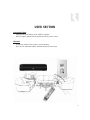
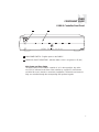
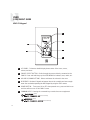
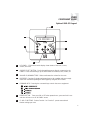
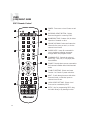
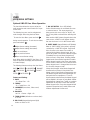
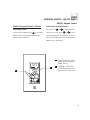
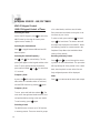
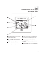
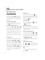
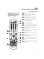
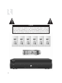
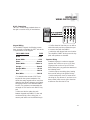
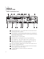
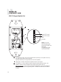
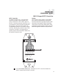
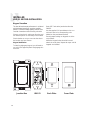
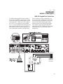
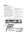
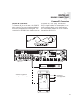

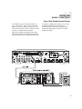
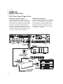
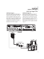
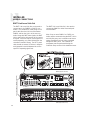
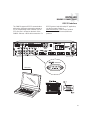
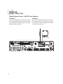
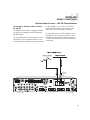
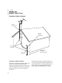

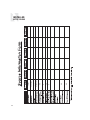
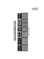
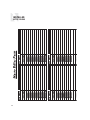
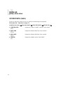
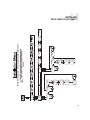
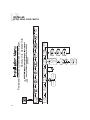
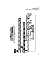
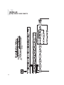
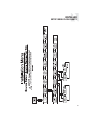
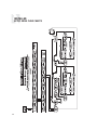
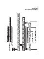
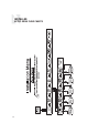
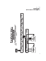
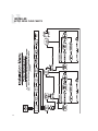
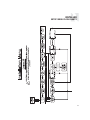
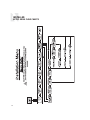
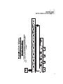
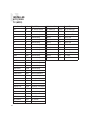
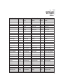
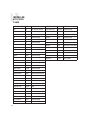
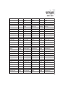
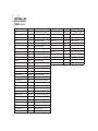
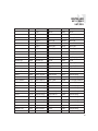
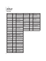
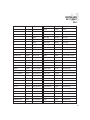
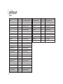
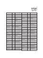
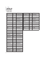
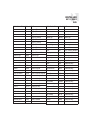
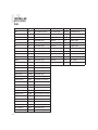

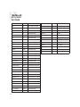
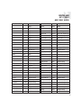
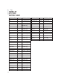
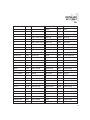
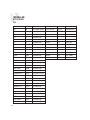
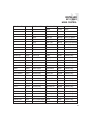
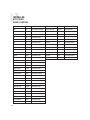
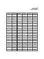
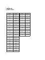

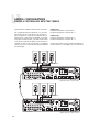
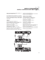
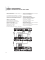
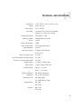


![Analyse de la tenue sismique des grands réservoirs[...]](http://vs1.manualzilla.com/store/data/006368585_1-4feb7f2835e3550c2e93b139d9c7a1e0-150x150.png)
![Analyse de la tenue sismique des grands réservoirs[...]](http://vs1.manualzilla.com/store/data/006357607_1-f6d301e5706d64d4958f6a452af28255-150x150.png)