1
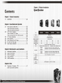
 MAUR VH9I000 Series
This time,
don't let XaserVI Mx slip away !
Thermaltake
CooLall YOUR LIFE
©2008 Thermaltake Technology Co., Ltd. All Rights Reserved. 2008.02
All other registered trademarks belong to their respective companies. www.fhermaltaxe.com
C Tested To Comply (СА
“ FCC Standards
FOR HOME OR OFFICE USE
8 Thermaltake
COOL YOUR LIFE
Contents
Chapter 1. Product Introduction
1.1
Specification ren 02
Chapter 2. Case Mechanical Operation
Li
№ No RN RN
VD UN A Ww
How to Open the Side Panel 10 03
-Open the lért-hand side panel) | He den on 03
-Open the right-hand side panel ----------------=========== 04
5:25” Device Installation en 05
„Hew| tö remove 5.25" dévicé mien 06
-How to put back the 5.25" drive bay cover ---------- 06
3.5" Device Installation (Am TETE 07
HDD Irs Rall BETS ie о иже ое ОСАО Я Ме рой = жом о ОГ oe e poe 08
How to Remove the HDD Cage rene pese 10
FO SIot [Tool -Free Sage HR TEE TT 11
Power Supply Installation +++ 44 es 12
Chapter3 Motherboard & Leads Installation
3.1
3.2
3.3
3.4
3.9
Motherboard Installation Rn не 13
Case LED connection HR du tes 14
USE Z.OrU0Nnectión TT 17 CEE ER TA ren РЯЙ 15
ALLIS Cannection | bh -i irr mn ner res rire n thats premarin ms 16
e-SATA connection 17 14 ECN aja ni e ae em mao 16
Chapter4 Other
4.1
Toughpower / Purepower / TR2 -----------==e=e=e=e=ee===e- 17
power supply series (optional)
XAsase YI MX vr9000 series This time, don't let Xaser YI Mx slip away!
Chapter |. Product Introduction
Specification
Model
Case Iype
Dimension (H*W*D)
Window side panel
Cable management
Adjustable PSU bridge
Material
Color
Cooling System
Motherboards
Drive Bays
-5.25" Drive Bay
-3.5" Drive Bay
-3.5" Drive Bay (Hidden)
Front 1/0
Expansion Slots
VH9000BWS
Net Welght / Gross Welght |
Yes
Yes
Yes
Chassis color: Black / Metal mesh : Red
VHI000BWS
a
Y A90005 WS
YHI000BNS
a
VA90005N5
Aclara: E VH9000SWS
el E
Middle Tower
520 x 220 x 520 mm
20.74 x 8.66 x 20.74 inch
8.35 kg / 18.40 |b
No Yes No
Yes Yes Yes
Yes Yes Yes
Front door: Plastics / Chassis: 1.0mm SECC
— Chassls color : Silver / Metal mesh : Black
Front (intake) : 120 x 120 x 25 mm TurboFan, 1300rpm, 17dBA
Rear (exhaust) : 120 x 120 x 25 mm blue LED fan, 1300rpm, 17dBA
Front (Intake) : 120 x 120 x 25 mm TurboFan, 1300rpm, 17dBA
Rear (exhaust) : 120 x 120 x 25 mm TurbecFan, 1300rpm, 17dBA
9.6" x 9.6" (Micro ATX), 12" x 9.6" (ATX)
5
1
4
e-SATA connector x 1, USB 2.0 x 2, HD Audio
7
Chapter 2 Case Mechanical Operation
2.1 How to Open the Side Panel
Open the left-hand side panel
To remove the left-hand side panel,
please remove thumb screws on the
back of the case.
Please find side panel key in the back
of the case, and open the side panel.
Pull out the left-hand side panel as
arrow shows.
=
Ll
a E Fa | o vi — L e a 1 - 1] pu & в 4 LL E т || со Ta Fan - TE Г, npg i В e y с e
XsaseVI MX vweoc0 series This time, don t let Xaser Y 1 Mx IN away
Make sure the side panel lock is opened.
Open the right-hand side panel
To remove the right-hand side panel,
please remove screws on the back of
the case.
Pull out the right-hand side panel as
arrow shows.
2.2 5.25" Device Installation
Remove the 5.25" drive bay
metal cover.
Put 5.25" device Into the drive bay till the locked-position.
Notice:
It is possible to secure the 5.25" device by screws If not
feel stable enough.
5 AsaseVI MX vwocoo Sertes This time, don 1 let XaserVI Mx slip away !
_ How to remove 5.25" device
Pull the right-hand side
of the lever to remove
the 5.25" device.
Install the 5.25" drive bay
cover as shown.
7
2.3 3.5" Device Installation 2.4 HDD Installation
Unlock the tool-free clip. Remove the 3.5" plastic cover.
Notice:
Please remove the 1st 5.25" drive bay cover
before taking away the 3.5" plastic cover.
Secure HDD using the clips onto
Secure the 3.5" device as shown. the HDD tray for both side.
AsaseVI MX vwscooSertes This time, dont let AaserVI Mx slip away !
Remove the HDD tray Dy
pressing the handle and
pull the tray out.
Place HDD on the tray.
saseVI MX vw9000 sertes Th
|
de
НН
TE EA
CH
Slide the HDD tray back to
the drive bay.
us |
* Organized HDD cable
A management.
me, dont let XaserVI Mx slip away !
2.5 How to Remove the HDD Cage
Unscrew the thumb screws of
the cage.
Push the handle down and pull
the cage out.
2.6
PCI Slot Tool-Free Usage
Release the plastic clip as shown.
Take off the PCI bracket.
Locate Graphic Card to the motherboard
through fixing it on the space of PCI
bracket and insert it to the PCI slot.
Notice:
Push back the plastic clip to secure the
Graphic Card.
"e
aserVI Mx slip away!
Fix the pin into the hole.
2.7 Power Supply Installation
Unscrew the PSU supporting bridge.
Place the PSU over the location as
shown and secure PSU by screws.
Fasten the supporting bridge using
screws.
Finish PSU Installation.
Chapter3 Motherboard & Leads Installation
3.1 Motherboard Installation
Each motherboard has different standoff layout. It Is highly
suggested that you refer to your motherboard's manual when
installing motherboard into the Case. XaserVI Mx is applicable
with , ATX & Micro ATX motherboards. Your motherboard may
require a special I/O Panel, which should be Included with your
motherboard.
Placement Direction:
When installing the motherboard, make sure you follow the
direction provided by your motherboard manufacturer, On
most standard motherboards, the edge with external ports
goes to the rear part of the chassis. Itis highly recommended
that you install CPU, heat sink and modular components
before fixing the motherboard inside the chassis.
“+
This slde towards
the rear of the
chassis
«a
EIN FOL
@ = the locations of
the screw holes. Note
these locations and
place included
standoffs gn the chassis
first.
T Ч ATE? ow Cm |
Above Illustration 15 a sample of what
the motherboard's layout. For more
detail screw hole placement, please
refer to your motherboard manual.
13 XsaseVI Mx vwenoo seres This time, don't let Xaser VI Mx slip away!
3.2 Case LED connection
On the front of the case, you can find some LEDs and switch leads
(POWER SW*1, POWER LED*1, H.D.D, LED*1, RESET SW*1)
Please consult user manual of your motherboard manufacturer, then
connect these leads to the panel header on the motherboard. These
leads are usually labeled; if not, please trace them back to the case
front to find out their source.
- POWER LED
connects to vour M/B at the PLED
- POWER SW
connects to the PWR connector on the motherboard
- H.D.D LED
connects to the 2-pin labeled HDD LED connector
- RESET SW
connects to the RSW connector on the motherboard
3.4 Audio Connection
3.3 USB 2.0 Connection e Please refer to the following Illustration
of Audio connector and your motherboard
user manual.
USB connection e Please select the motherboard which used
| AC'97 or HD Audio (Azalla), (be aware of
Please consult VOUr motherboard manual to find that your audio supports AC'97 or HD Audio
out the section of "USB connection”. (Azalia)) or It will damage your device(s).
* On some motherboards, the connectors for Audio are not the same
as the drawing below. Please check with your motherboard manual
before installing.
USB Function
PORT] L RED BLACK AUD GND
VCC / USB Power (+5C) for Port 4 RED NC PORTIR BROWN BLACK. PRESENCE?F
-D / USB Negative Signal for Port 4 WHITE BLACK GROUND / USB Ground PORT2R YELLOW ORANGE SENSEl RETURN
+D / USB Positive Signal for Port 4 GREEN GREEN +D / USB Positive Signal for Fort 3 SENSE SEND PURPLE KEY
GROUND / USB Ground BLACK WHITE -D/ USB Negative Signal for Fort 3 РОКТ2 1. BLUL GREEN SENSEZ RETURN
nr avc IE et a rh AUDIO AZALIA Function
Fit Mpa MICIN RED BLACK GROUND E Ground
Front Micropione MICPOWER BROWN NC
A ca R-OUT YELLOW YELLOW R-RET untar 1
NC KEY
asma LOUT BLUE BLUE L-RET A ||
AUDIO AG 97 Function
3.5 e-SATA connection
Connect this to your д
motherboard at SATA.
AsaseVl MX vwoooo serres This time, don t let Xaser YI Mx slip away!
17
Chapter4 Other
4.1 Toughpower / Purepower / TR2
power supply series (optional)
The Thermaltake Power Supply series specification meets latest Intel &
AMD dual & Quad core processors and NVIDIA & AMD high performance
graphic cards; it offers plenty of functions, which mainly include:
1. Automatic Fan Speed Control: All power supply can detect the inside
heat and automatically adjust the fan speed to provide adequate airflow.
2. Ultra Silent: Ball bearing fans with high reliability 140mm or 120mm
cooling fan and super low acoustic noise under all load condition.
3. Modularized Cable Management: To eliminate clutter and improve
airflow inside the case.
4, Dedicated Graphic Card Power: reduce the loading on current PSU and
no need to upgrade current PSU while running multi graphic cards mode.
The functions can assure all Thermaltake Power Supply meets the balance
in noise control and heat exhausted. All power supply provides complete
protection function as follow:
1. Over power protection.
2. Short circuit protection on all output.
3. Over voltage protection / Under voltage protection.
4, Over current protection.
>. Over temperature protection.
Besides, Thermaltake enables the quality assurance of all power supply:
100% Hi-POT and ATE Function Test, 100% Burn-In and AC Input cycled
on/off under high temperature condition. Furthermore, it has been approved
by UL, CUL, TUY, CB, FCC, CE, and BSMI.
There are three main products line of Thermaltake PSU which divided into
Toughpower, Purepower (include Purepower RX) and TR2 (include TR2 RX)
series. Please refer to
http: / /www.thermaltake.com/ product/Power/power_Index.asp
XsaseVI MX v#9000 series This time, don't let Xaser VI Mx slip away *