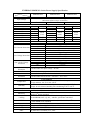
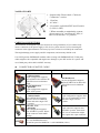
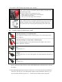
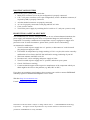
1
Precaution Notice
Only a technician, authorized by ENERMAX, is allowed to perform maintenance service!
Warranty is subject to void under unauthorized attempt to open the power case or
modification of any kinds, even attempted only, of the power supply or its components!
ENERMAX will not be responsible for damages caused by following situations:
Opening of the PSU case and/or modification of any component or cable without
ENERMAX’ written authorization
Ignoring connector’s wrong insertion prevention design by attaching a connector to a
device in wrong orientation
Connecting too many devices to one cable unit by using additional adaptor (Y cables) or
exceeding ENERMAX Eternity-connector recommendation which may cause voltage
drop to the devices and eventually damage them.
Usage of non-genuine ENERMAX modular cables
Damage caused by natural phenomena or uncontrollable forces, such as lightning,
flooding, fire, earthquake, etc.
This ENERMAX Technology Corporation product is warranted to be free from defects in
material and workmanship for a period of three (3) years from the date of purchase.
ENERMAX Technology Corporation agrees to repair or replace the product, at its own option
and at no charge, if, during the warranty period, it is returned to nearest ENERMAX
Technology Corporation subsidiary/agent with all shipping charges prepaid and bearing a
return merchandize authorization (RMA) number, and if inspection reveals that the product is
defective. Charges for removing or installing the product are excluded under the terms of this
warranty agreement. This warranty shall not apply to any product, which has been subject to
connection to a faulty power source, alteration, negligence, or accident, or to any product,
which has been installed other than in accordance with these instructions. In no event shall
ENERMAX Technology Corporation, or its subsidiaries, or agents be liable for damages for a
breach of warranty in an amount exceeding the purchase price of this product!
If you are uncertain whether or not your ENERMAX PSU is defective, please contact your
dealer/reseller for support!
Web Site: http://www.enermax.com
E-mail: [email protected]
© 2008, ENERMAX Technology Corporation, 15F-2, No. 888, Jing-Guo Road, Taoyuan City (330), Taiwan (R.O.C.), Tel.
+886-3-316-1675, Fax. +886-3-346-6640
All rights reserved. Actual product and accessories may differ from Illustrations. Information in this manual is subject to
change without prior notice. Printing errors and omissions excepted. All trademarks, registered trademarks and/or product
names mentioned are the property of their respective owners.
ENERMAX MODU82+ Series Power Supply Specification
Model
Spec.
Input Voltage
Input Current
EMD425AWT
EMD525AWT
EMD625AWT
AC Input
100-240VAC, 50-60Hz, automatic switching, Active PFC
(Maximum operation range: 90-265VAC)
6.7A-3A
7.5A-3.5A
9.5A-4A
DC Output
Rated
Combined
Rated
Combined
Rated
Combined
+3.3V
0.1-20A
0.1-24A
0.1-24A
120W
140W
140W
+5V
0.1-20A
0.1-24A
0.1-24A
+12V1
0.1-22A
0.1-25A
0.1-25A
396W
480W
600W
+12V2
0.5-22A
0.5-25A
0.5-25A
(33A)
(40A)
(50A)
+12V3
0-22A
0-25A
0.0-25A
-12V
0-0.6A
7.2W
0-0.6A
7.2W
0-0.6A
7.2W
+5Vsb
0-3A
15W
0-3A
15W
0-3A
15W
Total Power
425W
525W
625W
Protection Circuits
DC Rails
Trigger Range
+3.3V
28-40A
Over Current Protection
+5V
28-40A
+12V1/2/3
25–30A (425W) / 30-35A (525/625W)
DC Rails
Trigger Range
+3.3V
3.7 – 4.1V
Over Voltage Protection
+5V
5.7 – 6.5V
+12V1/2/3
13.1 – 14.5V
DC Rails
Trigger Range
(DC) Under Voltage
+3.3V
2.0-2.4V
Protection
+5V
3.3-3.7V
+12V1/2/3
8.5-9.5V
(AC) Under Voltage
Activated when AC input voltage < 80VAC
Protection
Over Power Protection Activated when output power > 110~150% of rated max load.
Short Circuit Protection Activated when any DC rails short circuited
Over Temperature
Activated when PSU heat sink > 90-100oC / 194 - 212oF
Protection
Environment
Temperature
Humidity
Power Factor
Efficiency
Cooling
MTBF
Dimension
Weight
Operation ambient: 0~40oC/32~104oF (for full rated output)
Storage ambient: -40~70 oC/-40~158 oF
Operation: to 85% relative humidity, non-condensing at 25 oC/77 oF
Storage: to 95% relative humidity, non-condensing at 50 oC/122 oF
Others
> 0.97 (Active PFC)
82%-85% @ 115VAC, 84-88% @ 230VAC
(80 PLUS® testing standard)
One 12cm axial fan, 450 – 1500RPM (±10% ) @ 25℃ ambient;
450-2000RPM(±10% ) @ 40℃ ambient, speed auto controlled.
> 100,000 hours at 70% of full rated load, 230VAC/50Hz, 25 oC
(MIL-HDBK-217F standard)
150 (w) x 86 (h) x 140 (d) mm
1.6kg(for 425W) / 1.8kg(for 525W & 625W) (without modular cables)
Safety
UL/cUL, TUV, BSMI, CCC, GOST, CB
EMC
CE (EN61204-3 standard), FCC, MIC
User’s Manual
Dear customer,
Thank you for choosing this ENERMAX MODU82+ power supply unit (PSU)! Please read
this manual carefully and follow its instructions, before installing the PSU.
We, ENERMAX, are globally renowned as the leading manufacturer of innovative PC
products of highest quality just like this MODU82+, which complies with the newest standard
for desktop class power supplies. We would like to draw your attention to the fact that PC is a
delicate systems, which require very specific conditions to work best for you without failing.
To avoid failures and to increase lifetime of your entire PC, we suggest you to make sure that:
Your PC is NOT located near a radiator or any other heat producing device
Your PC is NOT located near a magnetic device
Your PC is NOT located in a moist and/or dusty and/or vibrating environment
Your PC is NOT exposed to direct sunshine
Your PC is sufficiently cooled by additional fans
We do not recommend using PC systems with fanless cooling, because a potentially high inner
temperature decreases stability and lifetime of all components inside your PC!
COMPATIBILITY
ENERMAX MODU82+ series is compliant with:
Intel ATX12V Power Supply Design Guide v2.3 specification and downward
compatible with v2.0, v2.01 and v2.2.
ATX System Design Guide v2.2, v2.1
BTX/ EEB/ CEB/EPS12V
This PSU does not support MB with ISA expansion slot, which might require –5V
power. –5V has been cancelled from Intel ATX12V v1.3 specification onwards.
EXTRA NOTICE
If you use multi outlets AC extension cables to provide the system power, do not use
other high power consumption equipment, such as laser printers or radiators, on the
same extension cable to avoid exceeding cable’s safety loading capacity.
If you plan to add the UPS (Uninterruptible Power Supply) for your system, please
choose adequate watts/VA capacity UPS for possible supplied devices need. Ex.
Connected devices to same UPS
Estimated peak power draw (W/VA)
Dual CPU workstation with MODU82+ 525W
640W / 646VA
20” LCD monitor with speaker
55W / 94VA
A4 inkjet Printer
30W / 60VA
Suggest UPS minimum output power capacity:
725W or 800VA
Please do not mistake VA capacity as Watts, or use insufficient power UPS. This would
result less UPS battery runtime or the inability to power the system in battery mode.
This PSU is compatible with simulated and pure sine wave UPS.
NAME OF PARTS
1. Output cable: Please check “Cables &
Connectors” section.
2. 12cm fan.
3. AC inlet *
4. I/O switch*: individual PSU on/off switch
(I=ON, O=OFF)
* When assemble or maintain the system,
please remove AC cord from AC inlet, or
turn I/O switch into “O” position.
CABLES & CONNECTORS
All connectors are designed to prevent insertion in wrong orientation. If you cannot easily
insert a connector to the power supply or PC devices, please check if you are inserting the
connector in the right orientation. Do not try by force to insert it nor modify the connectors.
This might damage power supply and PC components, and warranty shall be void.
Use ONLY genuine ENERMAX modular cables coming with ENERMAX PSU. Third party
cables might not be compatible and might cause damage to your PSU and/or PC system, and
use of third party cable shall void PSU warranty.
CONNECTOR ON NATIVE CABLE
425W
525W & 625W
(20+4)P Mainboard,
in combined mode
24-pin configuration supports
24P Mainboard
latest ATX/BTX PC & dual CPU
24-pin configuration supports
EEB/CEB server/workstation
latest ATX/BTX PC & dual CPU
boards.
EEB/CEB server/workstation
(20+4)P Mainboard,
boards.
in split mode
20-pin configuration supports
former ATX systems.
4+4P CPU +12V,
8P CPU +12V
8-pin configuration supports dual
in combined mode
8-pin configuration supports
CPU server/workstation systems
dual CPU server/workstation
and some single CPU PC
systems and some single CPU
systems.
PC systems.
4+4P CPU +12V,
4P CPU +12V
in split mode
4-pin connector supports most
4-pin configuration supports
ATX/BTX systems. Some dual
most ATX/BTX systems. Please
CPU server/workstation might
use the connector with “12V”
also require this 4-pin connector.
marking.
FM (FAN RPM MONITOR)
For 12cm fan RPM detection.
Normal fan speed for MODU82+ is 450-2000RPM (±10% )
MODULAR SOCKETS & CABLE
Following graphic illustrates the modular sockets layout and DC rail distribution.
These two
sockets are not
available for
425W model.
Native Cables
MB, CPU
by +12V1
5-pin BLACK sockets
12Pin RED sockets
The
red
sockets
are for modular cable to power
The black sockets are for modular cable to
graphics card, CPU or RAM.
power drives or other peripheral.
MODULAR CABLES SUPPLIED
EMC011: 3 X SATA drives
Modular cable for SATA drives like ODD and HDD.
EMC012:3 x 4P Mole x (IDE/SCSI) drives
Modular cable for IDE/SCSI drives and other peripherals
EMC013: 3 x 4P Molex (IDE/SCSI) drives + 1 X FDD
connector
Modular cable for IDE/SCSI drives and peripheral, plus 1
FDD power connector.
EMC014: 2 x 6+2P (8P) PCI-E 2.0
Modular cable for 1 or 2 performance PCI Express
graphic cards, which needs 6P or 8P PCI-E connector.
EMC015: 1 x 6+2P (8P) PCI-E 2.0 (525W)
Modular cable for 1 performance PCI Express graphic
cards, which needs 6P or 8P PCI-E connector.
ATTACHING / DETACHING THE MODULAR CABLES
Attaching the modular cable to PSU
5-pin / 12-pin connector on modular cable and PSU’s modular socket
has a white arrow mark.
The steps to make correct connection is easy:
1. Black connector to black socket, and red to red.
2. Arrow mark to arrow mark.
3. Then you can easily plug in the connector.
Detaching the modular cable from PSU
5-pin / 12-pin connector on modular cable has two hooks to lock with
the PSU’s modular sockets. When unplug the modular cable from
PSU, please press two hooks together and gently pull out the cable.
CONNECTORS ON MODULAR CABLE
6+2P (8P) PCI Express, in combined mode
8-pin configuration supports latest extreme graphic cards, which require 8pin
PCI-E connector.
6+2P (8P) PCI Express, in split mode / 6P PCI Express
6-pin configuration supports most performance PCI-E graphic cards, which
require 6-pin PCI-E connector.
SATA
For SATA drives. *1
4P Molex
For IDE/SCSI drives or some AGP graphic card with traditional 4P power in
socket. *2
FDD
For floppy drive.
*1 Some SATA drives might accept SATA or 4P Molex power. Normally, use either one of
power connector to power the driver, BUT NOT BOTH! Please check the drive’s manual
for details.
*2 Some MB might require this connector to share the +12V current from 20-pin mainboard
connector to PCI-E slot. If your MB already supports 24-pin mainboard connector, you
may not add the 4P Molex power on it. Please check the MB’s manual for details.
BOOTING YOUR SYSTEM
Before booting your system, please check that
1. Main power connector (20 or 24-pin configuration) is properly connected.
2. CPU +12V power connector (4 or 8-pin configuration), and/or a 4P Molex connector (if
required by MB) is properly connected.
3. All other needed connectors are properly connected
4. AC cord is properly connected to wall plug and PSU AC inlet.
5. Close your PC chassis
6. Turn on the power supply by switching the I/O switch to “I”, and your system is ready.
PROTECTION, SAFETY & SECURITY
This ENERMAX PSU features multiple protections. In case of most abnormal situations, the
power supply will automatically turn off to avoid potential danger to itself and other PC
components. It is usually a malfunction of components or user’s negligence to trigger off a
protection event. In such circumstance, please check your PC devices and working
environment for malfunction:
1. Turn I/O switch of power supply into “O” position, or disconnect AC cord from wall
plug and power supply AC inlet.
2. Check PSU for temperature by simply touching it. If it is very hot, this can be caused by
malfunction of case fans or the PSU fan itself and/or wrong positioning of your PC.
3. Wait some minutes until PSU cools off
4. Reconnect AC cord to wall plug and power supply AC inlet
5. Turn I/O switch of power supply into “I” position, and reboot your system.
6. Check, if all fans are working
7. Contact technical support of the respective manufacturer of the component which you
think might be the cause to the problem (e.g. MB, GPU or PSU)
If you have any question or need support, please contact your reseller or nearest ENERMAX
subsidiary/agent or ENERMAX headquarter service center.
Web Site: http://www.enermax.com
E-mail: [email protected]
Information in this document is subject to change without notice.
Corporation.
©2008 ENERMAX Technology
All rights reserved. Reproduction in any manner whatsoever without the written
permission of ENERMAX is strictly forbidden.