1
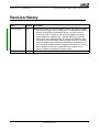
Revision Guide for
AMD Family 10h
Processors
Publication # 41322
Revision: 3.16
Issue Date: February 2008
© 2006–2008 Advanced Micro Devices, Inc. All rights reserved.
The contents of this document are provided in connection with Advanced Micro Devices,
Inc. (“AMD”) products. AMD makes no representations or warranties with respect to the
accuracy or completeness of the contents of this publication and reserves the right to make
changes to specifications and product descriptions at any time without notice. No license,
whether express, implied, arising by estoppel or otherwise, to any intellectual property
rights is granted by this publication. Except as set forth in AMD’s Standard Terms and
Conditions of Sale, AMD assumes no liability whatsoever, and disclaims any express or
implied warranty, relating to its products including, but not limited to, the implied warranty
of merchantability, fitness for a particular purpose, or infringement of any intellectual property right.
AMD’s products are not designed, intended, authorized or warranted for use as components in systems intended for surgical implant into the body, or in other applications
intended to support or sustain life, or in any other application in which the failure of
AMD’s product could create a situation where personal injury, death, or severe property or
environmental damage may occur. AMD reserves the right to discontinue or make changes
to its products at any time without notice.
Trademarks
AMD, the AMD Arrow logo, AMD Opteron, AMD Phenom, and combinations thereof, are trademarks of Advanced Micro Devices, Inc.
HyperTransport is a licensed trademark of the HyperTransport Technology Consortium.
Other product names used in this publication are for identification purposes only and may be trademarks of their respective companies.
41322 Rev. 3.16 February 2008
Revision Guide for AMD Family 10h Processors
Revision History
Date
Revision Description
February 2008
3.16
Added AMD Phenom™ brand information in Table 1 and Table 10; Added
Mixed Silicon Support section; Added Table 2: Supported Mixed Silicon
Revision Configurations and Deleted Table 9: Cross Reference of
Product Revision To OSVW_ID and renumbered tables accordingly;
Added AM2r2 String Tables 6 and 7; Updated MSRC001_0140 OS
Visible Work-around MSR0 (OSVW_ID_Length) and MSRC001_0141
OS Visible Work-around MSR1 (OSVW_Status) sections for OsvwId0;
Added errata #293, #295, #297–#298, #300–#302, #308–#309, #312,
#315, and #319; Editorial update to Suggested Workaround in erratum
#254; Updated Fix Planned in erratum #263 and updated entry in
Table 9; Updated Documentation Support section.
September 2007
3.00
Initial public release.
Revision History
3
Revision Guide for AMD Family 10h Processors
41322 Rev. 3.16
February 2008
Revision Guide for
AMD Family 10h Processors
The purpose of the Revision Guide for AMD Family 10h Processors is to communicate updated
product information to designers of computer systems and software developers. This revision guide
includes information on the following products:
• Dual-Core AMD Opteron™ processor
• Quad-Core AMD Opteron™ processor
•
•
Embedded AMD Opteron™ processor
AMD Phenom™ processor
This guide consists of three major sections:
•
Processor Identification: This section, starting on page 5, shows how to determine the processor
revision, program and display the processor name string, and construct the processor name string.
•
Product Errata: This section, starting on page 14, provides a detailed description of product
errata, including potential effects on system operation and suggested workarounds. An erratum is
defined as a deviation from the product’s specification, and as such may cause the behavior of the
processor to deviate from the published specifications.
•
Documentation Support: This section, starting on page 48, provides a listing of available
technical support resources.
Revision Guide Policy
Occasionally, AMD identifies product errata that cause the processor to deviate from published
specifications. Descriptions of identified product errata are designed to assist system and software
designers in using the processors described in this revision guide. This revision guide may be updated
periodically.
4
Revision History
41322 Rev. 3.16 February 2008
Revision Guide for AMD Family 10h Processors
Processor Identification
This section shows how to determine the processor revision, program and display the processor name
string, and construct the processor name string.
Revision Determination
Figure 1 shows the format of the value returned in EAX by CPUID Function 1.
Figure 1. Format of CPUID Value Returned by Function 1
Table 1 shows the identification number returned by the CPUID instruction for each revision of the
processor.
Table 1.
CPUID Values for AMD Family 10h Processor Revisions
Quad-Core
AMD Opteron™
Processor
Dual-Core
AMD Opteron™
Processor
Embedded
AMD Opteron™
Processor
AMD Phenom™
Processor
CPUID Function 1 EAX Value
DR-BA
00100F2Ah
00100F2Ah
00100F2Ah
N/Ah
DR-B2
00100F22h
00100F22h
00100F22h
00100F22h
Revision
Mixed Silicon Support
AMD Family 10h processors with different silicon revisions can be mixed in a multiprocessor
system. Mixed silicon revision support includes the AMD Opteron™ processor configurations as
shown in Table 2 on page 6:
Processor Identification
5
Revision Guide for AMD Family 10h Processors
Table 2.
41322 Rev. 3.16 February 2008
Supported Mixed Silicon Revision Configurations
Silicon Revison
DR-BA
DR-B2
DR-BA
YES
YES
DR-B2
YES
YES
Refer to Table 1 on page 5 for CPUID values for these revisions. Errata workarounds must be applied
according to revision as described in the Product Errata section starting on page 14 unless otherwise
noted in the workraound of an erratum.
6
Processor Identification
41322 Rev. 3.16 February 2008
Revision Guide for AMD Family 10h Processors
Programming and Displaying the Processor Name String
This section, intended for BIOS programmers, describes how to program and display the 48-character
processor name string that is returned by CPUID Fn8000_000[4:2]. The hardware or cold reset value
of the processor name string is 48 ASCII NUL characters, so the BIOS must program the processor
name string before any general purpose application or operating system software uses the extended
functions that read the name string. It is common practice for the BIOS to display the processor name
string and model number whenever it displays processor information during boot up.
Note:
Motherboards that do not program the proper processor name string and model number will not pass
AMD validation and will not be posted on the AMD Recommended Motherboard Web site.
The name string must be ASCII NUL terminated and the 48-character maximum includes that NUL
character.
The processor name string is programmed by MSR writes to the six MSR addresses covered by the
range C001_00[35:30]h. Refer to the BIOS and Kernel Developer’s Guide (BKDG) for
AMD Family 10h Processors, order# 31116, for the format of how the 48-character processor name
string maps to the 48 bytes contained in the six 64-bit registers of MSR C001_00[35:30]h.
The processor name string is read by CPUID reads to a range of CPUID functions covered by CPUID
Fn8000_000[4:2]. Refer to CPUID Fn8000_000[4:2] in the BIOS and Kernel Developer’s Guide
(BKDG) for AMD Family 10h Processors, order# 31116, for the 48-character processor name string
mapping to the 48 bytes contained in the twelve 32-bit registers of CPUID Fn8000_000[4:2].
Constructing the Processor Name String
This section describes how to construct the processor name string. BIOS uses the following fields to
create the name string:
•
BrandId[15:0] is from CPUID Fn8000_0001_EBX.
• String1[3:0] is defined to be BrandID[14:11]. This field is an index to a string value used to
create the processor name string. The definition of the string1 values are provided in Table 4
on page 9, and Table 6 on page 10.
• String2[3:0] is defined to be BrandID[3:0]. This field is an index to a string value used to
create the processor name string. The definition of the string1 values are provided in Table 5
on page 9, and Table 7 on page 10.
• Model[6:0] is defined to be BrandID[10:4]. This field is used to create the model number in
the name string. The model field represents a numerical model number which should be
converted to ASCII for display of the model number.
• Pg[0] is defined to be BrandID[15]. This field is used to index the appropriate page for the
String1, String2, and Model values.
Processor Identification
7
41322 Rev. 3.16 February 2008
Revision Guide for AMD Family 10h Processors
•
PkgTyp[3:0] is from CPUID Fn8000_0001_EBX. This field specifies the package type as defined
in the BIOS and Kernel Developer’s Guide (BKDG) for AMD Family 10h Processors, order
#31116, and is used to index the appropriate string tables from Table 3.
•
NC[7:0] is from CPUID Fn8000_0008[ECX]. This field identifies how many physical cores are
present as defined in the BIOS and Kernel Developer’s Guide (BKDG) for AMD Family 10h
Processors, order #31116, and is used to index the appropriate strings from Table 4 on page 9,
Table 5 on page 9, Table 6 on page 10, and Table 7 on page 10.
The name string is formed as follows:
1. Translate Model[6:0] into an ASCII value (Model), model numbers will range from 01-99. Model
numbers less than 10 should include a leading zero, e.g., 09.
2. If Model[6:0] = 00h, skip steps 3 through 6 and program the name string as follows:
If Pg[0] = 0, Name string = AMD Engineering Sample
Else If Pg[0] = 1, Name string = AMD Thermal Test Kit
3. Else select the appropriate string tables based on PkgTyp[3:0] from Table 3
4. Index into the referenced tables using String1[3:0], String2[3:0], and NC[7:0] to obtain the
String1 and String2 values.
5. If String1 is an undefined value skip step 6 and program the name string as follows:
Name String = AMD Processor Model Unknown
6. Else concatenate the strings with the two character ASCII translation of Model[3:0] from step 1 to
obtain the name string as follows:
If String2 is undefined, Name string = String1, Model
Else, Name string = String1, Model, String2
Table 3.
8
String Table Reference Per Package Type
PkgTyp
[3:0]
String1 Table
String2 Table
0h
Table 4 on page 9
Table 5 on page 9
1h
Table 6 on page 10
Table 7 on page 10
2h-Fh
Reserved
Reserved
Processor Identification
41322 Rev. 3.16 February 2008
Table 4.
Revision Guide for AMD Family 10h Processors
String1 Values for Socket Fr2 (1207) Processors
Pg[0]
NC
[7:0]
String
[3:0]
0b
01h
0h
0b
01h
0b
Note
Description
Dual-Core AMD Opteron(tm)
Processor 83
-
MP Server
1h
Dual-Core AMD Opteron(tm)
Processor 23
-
DP Server
03h
0h
Quad-Core AMD Opteron(tm)
Processor 83
-
MP Server
0b
03h
1h
Quad-Core AMD Opteron(tm)
Processor 23
-
DP Server
0b
03h
2h
Embedded AMD Opteron(tm)
Processor 83
-
MP Server
0b
03h
3h
Embedded AMD Opteron(tm)
Processor 23
-
DP Server
0b
03h
4h
Embedded AMD Opteron(tm)
Processor 13
-
UP Server
AMD Processor Model Unknown
-
All other values
Table 5.
Value
String2 Values for Socket Fr2 (1207) Processors
Pg[0]
NC
[7:0]
String
[3:0]
0b
xxh
0Ah
SE
1
0b
xxh
0Bh
HE
1
0b
xxh
0Ch
EE
1
0b
xxh
0Fh
All other values
Value
Note
Description
2
Reserved
-
Notes:
1. The string includes a space as the leading character.
2. The String2 index 0Fh is defined as an empty string, i.e., no suffix.
Processor Identification
9
41322 Rev. 3.16 February 2008
Revision Guide for AMD Family 10h Processors
Table 6.
String1 Values for Socket AM2r2 Processors
Pg[0]
NC
[7:0]
String
[3:0]
0b
03h
2h
All other values
Table 7.
Value
Note
AMD Phenom(tm)
-
Reserved
-
Client
String2 Values for Socket AM2r2 Processors
Pg[0]
NC
[7:0]
String
[3:0]
0b
03h
0h
00 Quad-Core Processor
-
0b
03h
2h
00B Quad-Core Processor
-
0b
03h
0Dh
0b
xxh
0Fh
All other values
Value
Quad-Core Processor
Note
1
2
Reserved
-
Notes:
1. The string includes a space as the leading character.
2. The String2 index 0Fh is defined as an empty string, i.e., no suffix.
10
Description
Processor Identification
Description
41322 Rev. 3.16 February 2008
Revision Guide for AMD Family 10h Processors
F4x164 Fixed Errata Register
Communicating the status of an erratum requiring a workaround within a stepping of a processor
family is necessary in certain circumstances. F4x164 is used to communicate the status of such an
erratum fix so that BIOS or system software can determine the necessity of applying the workaround.
Under these circumstances, the erratum workaround references the specified bit to enable software to
test for the presence of the erratum. The revisions of a processor, prior to the definition of a bit may
not be affected by the erratum. Therefore, software should use the stepping as the first criteria to
identify the applicability of an erratum. Once defined, the definition of the status bit will persist
within the family of processors.
Bits
Description
31:0
0000_0000h. Reserved.
F4x164 Fixed Errata Register
11
Revision Guide for AMD Family 10h Processors
41322 Rev. 3.16 February 2008
MSRC001_0140 OS Visible Work-around MSR0
(OSVW_ID_Length)
This register, as defined in AMD64 Architecture Programmer’s Manual Volume 2: System
Programming, order# 24593, is used to specify the number valid status bits within the OS Visible
Work-around status registers.
The default value of this register is 0000_0000_0000_0000h.
BIOS shall program the specified length as specified in Table 8 prior to hand-off to the OS.
Bits
Description
63:16
Reserved.
15:0
OSVW_ID_Length: OS visible work-around ID length. Read-write
Table 8.
OSVW_ID_Length Per Processor Revision
Revision Number
MSRC001_1040
Bits
15:0
12
DR-BA
DR-B2
0001h
0001h
MSRC001_0140 OS Visible Work-around MSR0 (OSVW_ID_Length)
41322 Rev. 3.16 February 2008
Revision Guide for AMD Family 10h Processors
MSRC001_0141 OS Visible Work-around MSR1
(OSVW_Status)
This register, as defined in AMD64 Architecture Programmer’s Manual Volume 2: System
Programming, order# 24593, provides the status of the known OS visible errata. Known errata are
assigned an OSVW_ID corresponding to the bit position with in the valid status field.
Operating system software should use MSRC001_0140 to determine the valid length of the bit status
field. For all valid status bits: 1=Hardware contains the erratum, and an OS software work-around is
required or may be applied instead of a BIOS workaround. 0=Hardware has corrected the erratum, so
an OS software work-around is not necessary.
The reset default value of this register is 0000_0000_0000_0000h.
BIOS shall program the state of the valid status bits prior to hand-off to the OS as defined in the
description below.
Bits
Description
63:1
OsvwStatusBits: OS visible work-around status bits. Read-write.
0
OsvwId0: OsvwId0 1= Hardware contains erratum #298, an OS workaround may be applied if
available. 0= Hardware has corrected erratum #298. In a multiprocessor platform, OsvwId0
should be set to 1 for all processors regardless of silicon revision when an affected processor is
present. Read-write.
MSRC001_0141 OS Visible Work-around MSR1 (OSVW_Status)
13
41322 Rev. 3.16 February 2008
Revision Guide for AMD Family 10h Processors
Product Errata
This section documents product errata for the processors. A unique tracking number for each erratum
has been assigned within this document for user convenience in tracking the errata within specific
revision levels. Table 9 cross-references the revisions of the part to each erratum. An “X” indicates
that the erratum applies to the revision. The absence of an “X” indicates that the erratum does not
apply to the revision. An “*” indicates advance information that the erratum has been fixed but not yet
verified. “No fix planned” indicates that no fix is planned for current or future revisions of the
processor.
Note: There may be missing errata numbers. Errata that have been resolved from early revisions of
the processor have been deleted, and errata that have been reconsidered may have been
deleted or renumbered.
Table 9.
No.
Cross-Reference of Product Revision to Errata
Revision
Number
Errata Description
DR-BA
DR-B2
57
Some Data Cache Tag Eviction Errors Are Reported As
Snoop Errors
No fix planned.
60
Single Machine Check Error May Report Overflow
No fix planned.
77
Long Mode CALLF or JMPF May Fail To Signal GP When
Callgate Descriptor is Beyond GDT/LDT Limit
No fix planned.
178
Default RdPtrInit Value Does Not Provide Sufficient Timing
Margin
X
X
244
A DIV Instruction Followed Closely By Other Divide
Instructions May Yield Incorrect Results
X
X
246
Breakpoint Due to An Instruction That Has an Interrupt
Shadow May Be Delivered to the Hypervisor
X
X
248
INVLPGA of A Guest Page May Not Invalidate Splintered
Pages
X
254
Internal Resource Livelock Involving Cached TLB Reload
X
X
260
REP MOVS Instruction May Corrupt Source Address
X
X
261
Processor May Stall Entering Stop-Grant Due to Pending
Data Cache Scrub
No fix planned.
263
Incompatibility With Some DIMMs Due to DQS Duty Cycle
Distortion
No fix planned
264
Incorrect DRAM Data Masks Asserted When DRAM
Controller Data Interleaving Is Enabled
269
ITT Specification Exceeded During Power-Up Sequencing
273
Lane Select Function Is Not Available for Link BIST on 8Bit HyperTransport™ Links In Ganged Mode
X
274
IDDIO Specification Exceeded During Power-Up
Sequencing
X
14
X
X
No fix planned.
Product Errata
X
41322 Rev. 3.16 February 2008
Table 9.
No.
Revision Guide for AMD Family 10h Processors
Cross-Reference of Product Revision to Errata (Continued)
Revision
Number
Errata Description
DR-BA
DR-B2
278
Incorrect Memory Controller Operation In Ganged Mode
X
279
HyperTransport™ Link RTT and RON Specification
Violations
X
280
Time Stamp Counter May Yield An Incorrect Value
X
X
293
Memory Instability After PWROK Assertion
X
X
295
DRAM Phy Configuration Access Failures
X
297
Single Machine Check Error May Report Overflow
298
L2 Eviction May Occur During Processor Operation To Set
Accessed or Dirty Bit
No fix planned.
X
X
300
Hardware Memory Clear Is Not Supported After Software
DRAM Initialization
X
X
301
Performance Counters Do Not Accurately Count MFENCE
or SFENCE Instructions
X
X
302
MWAIT Power Savings May Not Be Realized when Two or
More Cores Monitor the Same Address
X
X
308
Processor Stall in C1 Low Power State
X
X
309
Processor Core May Execute Incorrect Instructions on
Concurrent L2 and Northbridge Response
X
X
312
CVTSD2SS and CVTPD2PS Instructions May Not Round
to Zero
315
FST and FSTP Instructions May Calculate Operand
Address in Incorrect Mode
X
X
319
Inaccurate Temperature Measurement
X
X
No fix planned.
Product Errata
15
Revision Guide for AMD Family 10h Processors
41322 Rev. 3.16 February 2008
Table 10 cross-references the errata to each processor segment. An empty cell signifies that the erratum does not apply to the processor segment. “X” signifies that the erratum applies to the processor
segment. “N/A” signifies that the erratum does not apply to the processor segment due to the silicon
revision.
16
AMD Phenom™
Processor
Embedded
AMD Opteron™
Processor
Dual-Core
AMD Opteron™
Processor
Errata
Number
Cross-Reference of Errata to Processor Segments
Quad-Core
AMD Opteron™
Processor
Table 10.
57
X
X
X
X
60
X
X
X
X
77
X
X
X
X
178
X
X
X
X
244
X
X
X
X
246
X
X
X
X
248
X
X
X
N/A
254
X
X
X
X
260
X
X
X
X
261
X
X
X
X
263
X
X
X
X
264
X
X
X
X
269
X
X
X
X
273
X
X
X
X
274
X
X
X
N/A
278
X
X
X
N/A
279
X
X
X
N/A
280
X
X
X
X
293
X
X
X
X
295
X
X
X
X
297
X
X
X
X
298
X
X
X
X
300
X
X
X
X
301
X
X
X
X
302
X
X
X
X
308
X
X
X
X
309
X
X
X
X
312
X
X
X
X
315
X
X
X
X
319
X
X
X
X
Product Errata
41322 Rev. 3.16 February 2008
Revision Guide for AMD Family 10h Processors
Table 11 cross-references the errata to each package type. An empty cell signifies that the erratum
does not apply to the package type. “X” signifies that the erratum applies to the package type. “N/A”
signifies that the erratum does not apply to the package type due to the silicon revision.
Socket
AM2r2
Errata
Number
Cross-Reference of Errata to Package Type
Socket
Fr2 (1207)
Table 11.
57
X
X
60
X
X
77
X
X
178
X
X
244
X
X
246
X
X
248
X
X
254
X
X
260
X
X
261
X
X
263
X
X
264
X
X
269
X
X
273
X
X
274
X
X
278
X
X
279
X
X
280
X
X
293
X
X
295
X
X
297
X
X
298
X
X
300
X
X
301
X
X
302
X
X
308
X
X
309
X
X
312
X
X
315
X
X
319
X
X
Product Errata
17
Revision Guide for AMD Family 10h Processors
57
41322 Rev. 3.16 February 2008
Some Data Cache Tag Eviction Errors Are Reported As Snoop
Errors
Description
In some cases, the machine check error code on a data cache (DC) tag array parity error erroneously
classifies an eviction error as a snoop error.
The common cases of cache line replacements and external probes are classified correctly (as eviction
and snoop respectively). The erroneous cases occur when a tag error is detected during a DC eviction
that was generated by a hardware prefetch, a cache line state change operation, or a number of other
internal microarchitectural events. In such cases, the error code logged in the DC Machine Check
Status register (MC0_STATUS, MSR 0x401) erroneously indicates a snoop error.
Potential Effect on System
Internally detected DC tag errors may be reported to software as having been detected by snoops.
Depending upon machine check software architecture, the system response to such errors may be
broader than necessary.
Suggested Workaround
None required.
Fix Planned
No
18
Product Errata
41322 Rev. 3.16 February 2008
60
Revision Guide for AMD Family 10h Processors
Single Machine Check Error May Report Overflow
Description
A single parity error encountered in the data cache tag array may incorrectly report the detection of
multiple errors, as indicated by the overflow bit of the DC Machine Check Status register (bit 62 of
MSR 0x401).
Potential Effect on System
System software may be informed of a machine check overflow when only a single error was actually
encountered.
Suggested Workaround
Do not rely on the state of the OVER bit in the DC Machine Check Status register.
Fix Planned
No
Product Errata
19
Revision Guide for AMD Family 10h Processors
77
41322 Rev. 3.16 February 2008
Long Mode CALLF or JMPF May Fail To Signal GP When
Callgate Descriptor is Beyond GDT/LDT Limit
Description
If the target selector of a far call or far jump (CALLF or JMPF) instruction references a 16-byte long
mode system descriptor where any of the last 8 bytes are beyond the GDT or LDT limit, the processor
fails to report a General Protection fault.
Potential Effect on System
None expected, since the operating system typically aligns the GDT/LDT limit such that all
descriptors are legal. However, in the case of erroneous operating system code, the above described
GP fault will not be signaled, resulting in unpredictable system failure.
Suggested Workaround
None required, it is anticipated that long mode operating system code will ensure the GDT and LDT
limits are set high enough to cover the larger (16-byte) long mode system descriptors.
Fix Planned
No
20
Product Errata
41322 Rev. 3.16 February 2008
Revision Guide for AMD Family 10h Processors
178 Default RdPtrInit Value Does Not Provide Sufficient Timing
Margin
Description
Insufficient separation of the read pointer and write pointer in the synchronization FIFO can lead to
setup violations in the transmit FIFO.
Potential Effect on System
The setup violations may lead to data corruption.
Suggested Workaround
BIOS should program F2x[1, 0]78[3:0] (RdPtrInit) to 4’h5.
Fix Planned
Yes
Product Errata
21
Revision Guide for AMD Family 10h Processors
41322 Rev. 3.16 February 2008
244 A DIV Instruction Followed Closely By Other Divide
Instructions May Yield Incorrect Results
Description
A DIV instruction with a divisor less than 64 that is followed in close proximity by a DIV, IDIV, or
AAM instruction may produce incorrect results.
Potential Effect on System
Possible data corruption.
Suggested Workaround
Contact your AMD representative for information on a BIOS update.
Fix Planned
Yes
22
Product Errata
41322 Rev. 3.16 February 2008
Revision Guide for AMD Family 10h Processors
246 Breakpoint Due to An Instruction That Has an Interrupt Shadow
May Be Delivered to the Hypervisor
Description
A #DB exception occurring in guest mode may be delivered in the host context under the following
conditions:
•
A trap-type #DB exception is generated in guest mode during execution of an instruction with an
interrupt shadow, and
•
The instruction that generated the exception is immediately followed by an instruction resulting in
#VMEXIT.
Potential Effect on System
Unpredictable results due to an unexpected #DB exception.
Suggested Workaround
The hypervisor should have a valid interrupt gate in the IDT of the #DB handler entry and the handler
must be able to determine that this event has occurred. If the event is detected, the handler should
execute an IRET back to the hypervisor; one method that could be used to evaluate for this condition
is to compare the RIP pushed on the stack to the RIP of the instruction following VMRUN, if they are
equivalent then this event has occurred.
Fix Planned
Yes
Product Errata
23
Revision Guide for AMD Family 10h Processors
41322 Rev. 3.16 February 2008
248 INVLPGA of A Guest Page May Not Invalidate Splintered Pages
Description
When an address mapped by a guest uses a larger page size than the host, the TLB entry created uses
the size of the smaller page; this is referred to as page splintering. TLB entries that are the result of
page splintering may not be invalidated when the large page is invalidated in the guest using
INVLPGA.
Potential Effect on System
Unpredictable system behavior may result due to inconsistent entries in the TLB.
Suggested Workaround
The hypervisor should always intercept INVLPGA instructions. On returning to the guest from the
INVLPGA intercept the hypervisor should set TLB_Control = 1 in the VMCB to ensure correctness.
Fix Planned
Yes
24
Product Errata
41322 Rev. 3.16 February 2008
Revision Guide for AMD Family 10h Processors
254 Internal Resource Livelock Involving Cached TLB Reload
Description
Under a highly specific and detailed set of conditions, an internal resource livelock may occur
between a TLB reload and other cached operations.
Potential Effect on System
The system may hang.
Suggested Workaround
BIOS should set MSR C001_1023h[21] to 1b.
Fix Planned
Yes
Product Errata
25
Revision Guide for AMD Family 10h Processors
41322 Rev. 3.16 February 2008
260 REP MOVS Instruction May Corrupt Source Address
Description
The processor may corrupt the source address for REP MOVS instructions using 16- or 32-bit
addressing when a fault occurs on the first iteration and ECX is greater than 255 and EDI equals 0.
Potential Effect on System
Unpredictable system behavior.
Suggested Workaround
Contact your AMD representative for information on a BIOS update.
Fix Planned
Yes
26
Product Errata
41322 Rev. 3.16 February 2008
Revision Guide for AMD Family 10h Processors
261 Processor May Stall Entering Stop-Grant Due to Pending Data
Cache Scrub
Description
The processor may stall if a correctable error is identified by the data cache scrubber within a small
window of time before the processor enters a stop-grant state when another scrub is pending.
Potential Effect on System
The system may hang.
Suggested Workaround
BIOS should set MSRC001_1022[24].
Fix Planned
No fix planned.
Product Errata
27
Revision Guide for AMD Family 10h Processors
41322 Rev. 3.16 February 2008
263 Incompatibility With Some DIMMs Due to DQS Duty Cycle
Distortion
Description
Some DDR2 DIMMs exhibit a duty cycle distortion on the first DQS pulse of an incoming read
request which may cause the processor's DDR interface to miss a beat of data in a read burst.
Potential Effect on System
Undefined system behavior due to incorrect read data.
Suggested Workaround
BIOS should execute the following sequence prior to the DRAM initialization for DDR2-533 and
DDR2-667:
1. Write 00000800h to F2x[1, 0]9C_xD040F30.
2. Execute the DRAM Initialization sequence as defined in the BIOS and Kernel Developer's Guide
for AMD Family 10h Processors, order# 31116.
In addition, during DQS position training BIOS should set the DRAM read DQS timing control loop
range to 32 instead of 64.
Fix Planned
No.
28
Product Errata
41322 Rev. 3.16 February 2008
Revision Guide for AMD Family 10h Processors
264 Incorrect DRAM Data Masks Asserted When DRAM Controller
Data Interleaving Is Enabled
Description
The processor may incorrectly assert the DRAM data masks for writes less than a cacheline when
DRAM controller data interleaving is enabled.
Potential Effect on System
Data corruption.
Suggested Workaround
BIOS should set MSRC001_001F[36] (DisDatMsk) to 1b when F2x110[5] (DctDatIntLv) is set to 1b.
Fix Planned
Yes.
Product Errata
29
Revision Guide for AMD Family 10h Processors
41322 Rev. 3.16 February 2008
269 ITT Specification Exceeded During Power-Up Sequencing
Description
Processor current consumption may exceed the ITT maximum specified for C0/S0 operation if the
VTT voltage regulator is enabled before the VDDIO voltage regulator and the VDDIO regulator
enables a low resistance path to VSS while VTT - VDDIO > 400 mV.
Potential Effect on System
The VTT voltage regulator may shut down if ITT exceeds the platform design limit.
Suggested Workaround
None required if either of the following are true:
•
•
The VTT regulator is enabled at the same time or after the VDDIO regulator.
The VDDIO regulator does not enable a low resistance path to VSS while VTT - VDDIO >
400 mV.
For affected systems, the VTT voltage regulator should be enabled at the same time or after the
VDDIO voltage regulator during power-up power sequencing. Existing specifications limiting the
VDDIO to VTT relationship must be maintained.
Fix Planned
No
30
Product Errata
41322 Rev. 3.16 February 2008
Revision Guide for AMD Family 10h Processors
273 Lane Select Function Is Not Available for Link BIST on 8-Bit
HyperTransport™ Links In Ganged Mode
Description
The link BIST engine incorrectly initiates tests on sublink 1 rather than sublink 0 under the following
conditions:
•
•
•
•
The HyperTransport™ link is configured as an 8-bit link in ganged mode,
LaneSel[1], F0x[18C:170][13], is set to 1b,
BistEn, F0x[18C:170][10], is set to 1b, and
BIST is initiated by assertion of warm reset or a LDTSTOP_L disconnect.
Potential Effect on System
No impact to normal operational mode; however, the lane select function is not available for testing
asymmetric links or isolation of errors to the uplink or downlink on symmetric links.
Suggested Workaround
None.
Fix Planned
Yes
Product Errata
31
Revision Guide for AMD Family 10h Processors
41322 Rev. 3.16 February 2008
274 IDDIO Specification Exceeded During Power-Up Sequencing
Description
Processor current consumption may exceed the IDDIO maximum specified for C0/S0 operation
during power-up sequencing.
Potential Effect on System
None expected if the VDDIO voltage regulator is sourced by a RUN (running) plane from the power
supply during power-up sequencing. Otherwise, during power-up sequencing the VDDIO voltage
regulator may shut down if IDDIO exceeds the platform budget or the power supply may shut down if
the SUS (suspend) rail current capacity is exceeded.
Suggested Workaround
Three options exist to ensure the VDDIO voltage regulator is sourced with sufficient current during
processor power-up sequencing:
1. Enable the VDDIO voltage regulator after POWER_GOOD is asserted from the high-current
(RUN) source rail.
2. Provide a path for a high-current (RUN) rail to source current to the VDDIO voltage regulator
prior to POWER_GOOD assertion from the high-current (RUN) rail. This solution assumes the
high-current (RUN) rail is enabled early enough relative to enabling the VDDIO voltage
regulator.
3. Choose a power supply with increased capacity for the rail sourcing the VDDIO voltage regulator
during power-up sequencing. The capacity required is system specific and should allocate 7 amps
per processor in the power budget. The following is an example of a supply current capacity
calculation assuming a 5 V suspend rail and 3 W rest of system power for a single-processor
system. Other platform-specific factors such as power supply or regulator efficiencies should also
be considered.
• Rest of system (non-processor) power = 3 W
• Processor power = 7 A/processor * 1 processor * 1.8 V = 12.6 W
• Source rail capacity = (rest of system power + processor power) / source rail voltage; (3 W +
12.6 W) / 5 V = 3.12 A
Fix Planned
Yes
32
Product Errata
41322 Rev. 3.16 February 2008
Revision Guide for AMD Family 10h Processors
278 Incorrect Memory Controller Operation In Ganged Mode
Description
The DRAM controller 0 (DCT0) and DRAM controller 1 (DCT1) refresh counters may not be
initialized to the same value using hardware controlled DRAM initialization when operating in
ganged mode.
Potential Effect on System
Incorrect memory controller operation.
Suggested Workaround
BIOS should apply the following workaround prior to DRAM training when using hardwarecontrolled DRAM initialization and F2x110[4] (DctGangEn) is set to 1b.
1. Disable automatic refresh cycles by setting F2x08C[18] (DisAutoRefresh) to 1b.
2. Begin DRAM initialization by setting F2x090[0] to 1b.
3. Poll F2x090[0] until it reads 0b then wait at least 50 microseconds.
4. Enable automatic refresh cycles by clearing F2x08C[18] (DisAutoRefresh) to 0b.
5. Disable automatic refresh cycles by setting F2x08C[18] (DisAutoRefresh) to 1b.
6. Enable automatic refresh cycles by clearing F2x08C[18] (DisAutoRefresh) to 0b.
7. Begin DRAM training.
In addition, when resuming from S3, BIOS should apply the following workaround.
1. Disable automatic refresh cycles by setting F2x08C[18] (DisAutoRefresh) to 1b.
2. Initiate exit from self refresh by setting F2x090[1] to 1b.
3. Poll F2x090[1] until it reads 0b then wait at least 50 microseconds.
4. Enable automatic refresh cycles by clearing F2x08C[18] (DisAutoRefresh) to 0b.
5. Disable automatic refresh cycles by setting F2x08C[18] (DisAutoRefresh) to 1b.
6. Enable automatic refresh cycles by clearing F2x08C[18] (DisAutoRefresh) to 0b.
Fix Planned
Yes
Product Errata
33
Revision Guide for AMD Family 10h Processors
41322 Rev. 3.16 February 2008
279 HyperTransport™ Link RTT and RON Specification Violations
Description
The RTT and RON specifications for the HyperTransport™ link may be violated on some processor
revisions.
Potential Effect on System
These violations do not result in any other HyperTransport™ link electrical specification violations.
There are no known functional failures related to this problem.
Suggested Workaround
None required.
Fix Planned
Yes.
34
Product Errata
41322 Rev. 3.16 February 2008
Revision Guide for AMD Family 10h Processors
280 Time Stamp Counter May Yield An Incorrect Value
Description
Reads of the time stamp counter may yield an inconsistent result.
Potential Effect on System
Undefined behavior for software that relies on a continuously increasing time stamp counter value.
Suggested Workaround
Contact your AMD representative for information on a BIOS upgrade.
Fix Planned
Yes.
Product Errata
35
Revision Guide for AMD Family 10h Processors
41322 Rev. 3.16 February 2008
293 Memory Instability After PWROK Assertion
Description
After PWROK is asserted, the DRAM DQS DLL may not lock properly.
Potential Effect on System
The system may have degraded memory margins leading to unreliable DRAM signaling. In some
circumstances, this may cause BIOS to degrade the memory speed.
Suggested Workaround
During DRAM controller (DCT) initialization, system software should perform the following
workaround to every DCT in the system:
1. Perform a dummy DRAM read to any address on any DIMM attached to the DCT.
2. Write 0000_8000h to register F2x[1, 0]9C_xD080F0C.
3. Wait at least 300 nanoseconds.
4. Write 0000_0000h to register F2x[1, 0]9C_xD080F0C.
5. Wait at least 2 microseconds.
During cold reset or resume from S4 state, the workaround should be performed immediately prior to
the Receiver Enable Training. During resume from S3 state, the workaround should be applied after
F2x[1, 0]90[ExitSelfRef] has been cleared and prior to restoring the F2x[1, 0]9C registers.
Fix Planned
Yes.
36
Product Errata
41322 Rev. 3.16 February 2008
Revision Guide for AMD Family 10h Processors
295 DRAM Phy Configuration Access Failures
Description
Under a highly specific set of asynchronous timing conditions established during cold boot (S5 to S0
transition) or resume (S4 or S3 to S0 transition), the skew between the DRAM controllers (DCTs) and
DRAM phy may lead to unreliable communication for DRAM phy configuration accesses.
Potential Effect on System
The system may hang during DRAM configuration accesses when using DCT link ganged mode
([DRAM Controller Select Low Register] F2x110[DctGangEn] = 1b), or fail DRAM training in link
ganged mode or in link unganged mode.
Suggested Workaround
Contact your AMD representative for information on a BIOS update.
Fix Planned
Yes
Product Errata
37
Revision Guide for AMD Family 10h Processors
41322 Rev. 3.16 February 2008
297 Single Machine Check Error May Report Overflow
Description
A single tag snoop parity error encountered in the instruction cache tag array may incorrectly report
the detection of multiple errors, as indicated by the overflow bit of the IC Machine Check Status
register (MSR 0000_0405[62]).
Potential Effect on System
System software may be informed of a machine check overflow when only a single error was actually
encountered.
Suggested Workaround
None required.
Fix Planned
No
38
Product Errata
41322 Rev. 3.16 February 2008
Revision Guide for AMD Family 10h Processors
298 L2 Eviction May Occur During Processor Operation To Set
Accessed or Dirty Bit
Description
The processor operation to change the accessed or dirty bits of a page translation table entry in the L2
from 0b to 1b may not be atomic. A small window of time exists where other cached operations may
cause the stale page translation table entry to be installed in the L3 before the modified copy is
returned to the L2.
In addition, if a probe for this cache line occurs during this window of time, the processor may not set
the accessed or dirty bit and may corrupt data for an unrelated cached operation.
Potential Effect on System
One or more of the following events may occur:
•
•
•
Machine check for an L3 protocol error. The MC4 status register (MSR 0000_0410) will be
equal to B2000000_000B0C0F or BA000000_000B0C0F. The MC4 address register (MSR
0000_0412) will be equal to 26h.
Loss of coherency on a cache line containing a page translation table entry.
Data corruption.
Suggested Workaround
BIOS should set MSR C001_0015h[3] (HWCR[TlbCacheDis]) to 1b and MSR C001_1023h[1] to 1b.
In a multiprocessor platform, the workaround above should be applied to all processors regardless of
silicon revision when an affected processor is present.
Fix Planned
Yes
Product Errata
39
Revision Guide for AMD Family 10h Processors
41322 Rev. 3.16 February 2008
300 Hardware Memory Clear Is Not Supported After Software DRAM
Initialization
Description
When using software-controlled DRAM device initialization through EnDramInit (F2x[1, 0]7C
DRAM Initialization Register[31]), hardware memory clear using MemClrInit (F2x110 DRAM
Controller Select Low Register[3]) does not function.
Potential Effect on System
After BIOS sets MemClrInit (F2x110[3]), the hardware will not clear memory and will not set
MemCleared (F2x110[10]). The BIOS will hang waiting for the operation to complete.
Suggested Workaround
BIOS should use hardware initialization of DRAM using InitDram (F2x[1, 0]90 DRAM
Configuration Low Register[0]). If BIOS uses software initialization, alternative methods to initialize
ECC must be used.
Fix Planned
Yes
40
Product Errata
41322 Rev. 3.16 February 2008
Revision Guide for AMD Family 10h Processors
301 Performance Counters Do Not Accurately Count MFENCE or
SFENCE Instructions
Description
MFENCE and SFENCE instructions are not accurately counted by the performance monitor when
MSRC001_000[3:0][7:0] (EventSelect) is 1D4h, or 1D5h.
Potential Effect on System
Performance monitoring software will not be able to count MFENCE and SFENCE instructions.
Suggested Workaround
None.
Fix Planned
Yes
Product Errata
41
Revision Guide for AMD Family 10h Processors
41322 Rev. 3.16 February 2008
302 MWAIT Power Savings May Not Be Realized when Two or More
Cores Monitor the Same Address
Description
Execution of the MONITOR instruction may cause another core to exit the monitor event pending
state.
Potential Effect on System
No functional impact; however, the power savings associated with the MWAIT instruction may not be
realized.
Suggested Workaround
Contact your AMD representative for information on a BIOS update.
Fix Planned
Yes
42
Product Errata
41322 Rev. 3.16 February 2008
Revision Guide for AMD Family 10h Processors
308 Processor Stall in C1 Low Power State
Description
Under a highly specific set of internal timing conditions, an L3 eviction may stall for a processor core
that has entered the C1 (Halt) state. If the processor core has already entered the low power state and
the CpuPrbEn bit in the C1 SMAF is 0b (F3x84[24]), the stall persists until the processor core comes
out of the low power state.
Potential Effect on System
The system may hang.
Suggested Workaround
Contact your AMD representative for information on a BIOS update.
Fix Planned
Yes
Product Errata
43
Revision Guide for AMD Family 10h Processors
41322 Rev. 3.16 February 2008
309 Processor Core May Execute Incorrect Instructions on
Concurrent L2 and Northbridge Response
Description
Under a specific set of internal timing conditions, an instruction fetch may receive responses from the
L2 and the Northbridge concurrently. When this occurs, the processor core may execute incorrect
instructions.
Potential Effect on System
Unpredictable system behavior.
Suggested Workaround
BIOS should set MSR C001_1023h[23].
Fix Planned
Yes
44
Product Errata
41322 Rev. 3.16 February 2008
Revision Guide for AMD Family 10h Processors
312 CVTSD2SS and CVTPD2PS Instructions May Not Round to Zero
Description
The Convert Scalar Double-Precision Floating Point to Scalar Single-Precision Floating Point
(CVTSD2SS) and Convert Packed Double-Precision Floating Point to Packed Single-Precision
Floating Point (CVTPD2PS) instructions do not round to zero when the Flush to Zero and Underflow
Mask bits (MXCSR bits 15 and 11) are set to 1b and the double-precision operand is less than the
smallest single-precision normal number.
Potential Effect on System
The conversion result will yield the smallest single-precision normalized number rather than zero. It
is not expected that this will result in any anomalous software behavior since enabling flush to zero
provides less precise results.
Suggested Workaround
None
Fix Planned
No
Product Errata
45
Revision Guide for AMD Family 10h Processors
41322 Rev. 3.16 February 2008
315 FST and FSTP Instructions May Calculate Operand Address in
Incorrect Mode
Description
A Floating-Point Store Stack Top (FST or FSTP) instruction in 64-bit mode that is followed shortly
by an instruction that changes to compatibility mode may incorrectly calculate the operand address
using compatibility mode. Also, an FST or FSTP instruction in compatibility mode that is followed
shortly by an instruction that changes to 64-bit mode may incorrectly calculate the operand address
using 64-bit mode.
The incorrect mode for address calculation is only used under highly specific internal timing
conditions and when the Underflow Mask bit (FCW bit 4) is set and the data to be stored by the FST
or FSTP instruction is a denormalized (tiny) number.
Potential Effect on System
The processor may store to an incorrect address. This may cause an unexpected page fault or
unpredictable system behavior. This sequence has not been observed in any production software.
Suggested Workaround
Contact your AMD representative for information on a BIOS update.
Fix Planned
Yes
46
Product Errata
41322 Rev. 3.16 February 2008
Revision Guide for AMD Family 10h Processors
319 Inaccurate Temperature Measurement
Description
The internal thermal sensor used for CurTmp (F3xA4[31:21]), hardware thermal control (HTC),
software thermal control (STC), and the sideband temperature sensor interface (SB-TSI) may report
inconsistent values.
Potential Effect on System
HTC, STC and SB-TSI do not provide reliable thermal protection. This does not affect THERMTRIP.
Suggested Workaround
None. Systems should be designed with conventional thermal control and throttling methods or
utilize PROCHOT_L functionality based on temperature measurements from an analog thermal diode
(THERMDA/THERMDC).
Systems should not rely on the HTC features, STC features or use SB-TSI.
Software should not modify HtcTmpLmt (F3x64[22:16]) or enable any of the STC features by setting
StcPstateEn, StcApcTmpLoEn, StcApcTmpHiEn, StcSbcTmpLoEn, or StcSpcTmpHiEn
(F3x68[5,3:0]).
Fix Planned
Yes
Product Errata
47
Revision Guide for AMD Family 10h Processors
41322 Rev. 3.16 February 2008
Documentation Support
The following documents provide additional information regarding the operation of the processor:
•
BIOS and Kernel Developer’s Guide (BKDG) for AMD Family 10h Processors, order# 31116
•
AMD64 Architecture Programmer's Manual Volume 1: Application Programming, order# 24592
•
AMD64 Architecture Programmer's Manual Volume 2: System Programming, order# 24593
•
AMD64 Architecture Programmer's Manual Volume 3: General-Purpose and System Instructions,
order# 24594
•
AMD64 Architecture Programmer's Manual Volume 4: 128-Bit Media Instructions, order# 26568
•
AMD64 Architecture Programmer's Manual Volume 5: 64-Bit Media and x87 Floating-Point
Instructions, order# 26569
•
AMD CPUID Specification, order# 25481
•
AMD Family 10h Server and Workstation Processor Power and Thermal Data Sheet, order#
43374
•
AMD Family 10h Desktop Processor Power and Thermal Data Sheet, order# 43375
See the AMD Web site at www.amd.com for the latest updates to documents
48
Documentation Support