1
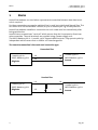
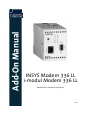
Add-On Manual
INSYS Modem 336 LL
i-modul Modem 336 LL
(Modem for LeasedLine operation)
Aug-06
Copyright © August 06 INSYS MICROELECTRONICS GmbH
Any duplication of this manual is prohibited. All rights on this documentation and the
devices are with INSYS MICROELECTRONICS GmbH Regensburg.
Restrictions of guarantee
This handbook contains a concise description. The compilation of the text has been made
with the utmost care. Despite all efforts, there may be deviations compared with the actual functions. No guarantee can therefore be given for the accuracy of the contents. We
can neither take over a legal responsibility nor any liability for incorrect information and
their consequences. Suggestions for improvements and comments are gladly accepted.
Trademarks
The use of a trademark not shown below is not an indication that it is freely available for
use.
MNP is a registered trademark of Microcom Inc.
IBM PC, AT, XT are registered trademarks of International Business Machine Corporation.
INSYS ® is a registered trademark of INSYS MICROELECTRONICS GmbH.
Windows™ is a registered trademark of Microsoft Corporation.
Publisher:
INSYS MICROELECTRONICS GmbH
Waffnergasse 8
D-93047 Regensburg, Germany
Phone:
+49 (0)941/56 00 61
Fax:
+49 (0)941/56 34 71
e-mail:
[email protected]
Internet:
http://www.insys-tec.de
Subject to technical changes as well as correction.
Date: Aug-06
Item: 31-22-03.070 english
Version: 1.1
Language: EN
Inhalt
1
BASICS ........................................................................ 4
2
MODEM CONFIGURATION ......................................... 6
2.1
CONFIGURATION MODE ..............................................................6
2.2
TRANSMIT LEVEL ........................................................................7
2.3
PING MODE AS CONNECTION SAFEGUARD ....................................7
2.4
STATUS TRANSMISSION OF THE DIGITAL INPUTS ..............................8
2.5
REMOTE CONFIGURATION ............................................................8
3
DIAGNOSIS AND TESTING OF THE PATH .................... 9
3.1
LINE OPTIMIZATION ...................................................................9
3.2
ERROR SOURCES ........................................................................9
3.3
DATA PROTOCOL DEPENDANT SETTINGS ........................................9
4
TECHNICAL DATA ..................................................... 11
5
FEATURES ................................................................. 12
6
DECLARATION OF CONFORMITY .............................. 13
Aug-06
3
Basics
1
INSYS Modem 336 LL
i-modul Modem 336 LL
Basics
Leased line modems are used when a permanent connection between two data terminals is required.
For these connections no regular switched line is used, but a dedicated (leased) line. This
can either be a line leased from Telekom, or just an unused pair e.g. on the premises.
Leased line modems establish a connection via such a two wire line immediately after
being switched on.
Leased lines are sometimes “serviced” which means they don’t represent a direct two
wire connection. The end terminals are supplied using a power supply unit.
The INSYS Modem 366 LL / i-modul 336 LL supports both variants. They operate polarityindependent which means that a1 and b1 are interchangeable.
The two wire connection is the most used connection type.
Unserviced line
i-modul 336 LL /
INSYS Modem 336 LL
Originate
LA
LA
LB
LB
i-modul 336 LL /
INSYS Modem 336 LL
Answer
Serviced line
LA
i-modul 336 LL /
INSYS Modem 336 LL
Originate
4
LB
LA
LB
i-modul 336 LL /
INSYS Modem 336 LL
Answer
Aug-06
INSYS Modem 336 LL
i-modul Modem 336 LL
Basics
Note
For INSYS Modem 336 LL 4.1 and i-modul 336 LL 3.0:
Use AT&L<n> to switch between two wire operation (AT&L0) and
four wire operation (AT&L1).
During four wire operation, one pair each is needed for each transmission path (Originate → Answer and Answer → Originate). This will prevent problems with the terminating set (the part of the modem which separates received and sent data) for strongly maladjusted lines.
Four wire line
i-modul 336 LL /
INSYS Modem 336 LL
Originate
LB1
LB1
LB
LB
LA
LA
LA1
LA1
i-modul 336 LL /
INSYS Modem 336 LL
Answer
Note
For leased line modems, it is required that one modem is operated
in originate mode and the other modem in answer mode.
For the connection start, the same protocols are used for switched line and leased line
operation.
The manufacturer will deliver completely pre-configured devices – Originate or Answer –
for two wire operation.
The difference lies in the factory settings for the S registry values (ATS11 und ATS7).
Originate:
Answer:
ATS11=3,
ATS11=1,
ATS7=50
ATS7=30
Note
For leased line modems, the same AT commands and S registries as
for switched line modems apply (see the Designer’s Guide i-modul
Modem or the User Manual INSYS Modem 336/56k) The only difference is the registry ATS11. For the switching line modem this
setting defines the DTC time setting, and for the LL modem it defines the switching between Originate and Answer.
Basically, all connection protocols, error correction and compression methods which are
used for switched line operation, may also be used for the leased line mode. The AT
commands to set the desired protocol are identical to those of the switched line modem.
Aug-06
5
Modem Configuration
INSYS Modem 336 LL
i-modul Modem 336 LL
2
Modem Configuration
2.1
Configuration Mode
The leased line modems have the same AT command set as the switched line versions. As
the modems attempt to establish a connection as soon as they are connected to a power
supply unit, they must first be returned to Configuration Mode.
The configuration mode is activated by pressing the RESET key (rail version) for a very
short time (<1s) or by briefly applying a RESET signal (module version, RESET is Low active!).
The OH signal is inactivated (the modem “hangs up) and the modem can be configured
using AT commands.
After the configuration, the Connection State is activated, when:
-
The operating voltage is switched off and back on,
-
A Reset (>3s) is triggered, or
- The command “ATZ” is entered.
A built-in safety mechanism will furthermore automatically trigger a RESET, if no command is entered in configuration mode for more than 2 minutes. This mechanism will
protect the modem from unintentional interference pulses on the RESET line.
Prior to the configuration, the requested speed must be entered with the AT command
AT*S<n>&W, the data format with the AT command (AT*U<n>&W), and then saved. During the connection state, the INSYS Modems 336 LL can no longer be addressed via AT
commands.
The settings (baud rate, data format, error correction, data compression) must be the
same to guarantee trouble-free operation. For varied baud rates, handshaking must be
used to prevent the modem buffers from overflowing (the modem buffers can accommodate approximately 256 bytes in both the receive and send direction. If the individual
messages that are to be transmitted are shorter than the buffer length, and if a sufficient delay time exists between the messages, even for varied baud rates handshaking
may be renounced).
Note
By default, handshake is deactivated (AT&K0) for the INSYS Modem
336 LL / i-modul Modem 336 LL 3.0. If handshake (RTS/CTS or
XON/XOFF) is required, it must be activated with the command
AT&K<n> (see manual).
Note
In contrast to the INSYS Modem 336 LL 4.0 (i-modul Modem 336), the
error correction for the INSYS Modem 336 LL 4.1 (i-modul Modem 336
LL 3.0) is set to V.42 by default (AT\N4). To enable operation with the
previous version (error correction by default MNP4 AT\N5), the INSYS
Modem 336 LL 4.1 (i-modul Modem 336 LL 3.0) must be configured
6
Aug-06
INSYS Modem 336 LL
i-modul Modem 336 LL
Modem Configuration
with AT\N5 at MNP4.
Note
All settings must be saved using AT&W as they are otherwise lost when
the connection is restarted!
2.2
Transmit Level
It may be required to adjust the transmit level of the modem to adapt it to the path.
The transmit level is set at –15dBm by the manufacturer and can be changed in the S
registry (ATS91). Transmit levels from –15 dBm (ATS91=15) to -6 dBm (ATS91=6) may
be set. The transmit level should be set to the same setting on both sides.
Attention!
In practice, a lower transmit level is often better, also for longer paths,
than a level that is too high.
If a transmit level is too high, malfunctions due to maladjustments and reflections may
prevent the signals of the remote terminal at the receiving modem to be interpreted correctly.
Note
If connection problems occur, one should always try to first reduce the
transmit level.
Gradually, set the S91 registry to a lower value.
2.3
PING Mode as Connection Safeguard
The leased line modems have an additional connection safeguard built in, which prevents a modem connection to “hang up”.
This connection safeguard sends a short test message to the remote terminal in cyclical
intervals (every 20 seconds). If a modem does not get a proper test message from the
remote terminal on the receive side within 120 seconds it assumes that the connection is
no longer established and tries to re-establish the connection.
The used test message is initiated by a pre-defined character in the S registry
(ATS8=<n>). Factory setting: ATS8=3
According to the used protocol, it may be of advantage to change the initial character to
avoid unnecessary data transfer between the modems. All characters may be set with
the ASCII code 1..255.
ATS8=0 will completely deactivate the connection safeguard.
Note
The initial character must be set to the same character on both sides
to enable the modems to recognize the test messages of the remote
side. If different ping characters are set, the remote terminal will receive invalid characters and the connection will be interrupted in cyclical intervals.
Aug-06
7
Modem Configuration
INSYS Modem 336 LL
i-modul Modem 336 LL
Note
PING mode will work with all buffered modes. It will not work with
direct mode (AT\N1).
2.4
Status Transmission of the Digital Inputs
If ping mode is activated (see Chapter 2.3), the status of the alarm inputs is automatically
transmitted to the switch outputs of the other modem, together with the ping messages.
A status change at one of the alarm inputs will automatically execute the sending of a
ping packet to the remote terminal. The maximum transmittable frequency is at approximately 0.5 Hz, i.e. the transmission may only be used for slowly changing status
lines.
2.5
Remote configuration
If connection safeguard is activated (see Chap. 1.3), this may result in problems during
the processing of AT commands in remote configuration mode.
For this reason, the connection safeguard should be deactivated at both modems prior to
the configuration.
Switching to command mode
<Pause>+++<Pause>
Deactivating the connection safeguard (local)
ATS8=0
Switching to remote configuration mode
<Pause>****<Pause>
Deactivating the connection safeguard (remote)
ATS8=0
Configuring the remote modem …
AT…
After the configuration, you can reactivate the connection safeguard at both modems
with ATS8=3&W (default).
8
Aug-06
INSYS Modem 336 LL
i-modul Modem 336 LL
3
Diagnosis and Testing of the Path
3.1
Line Optimization
Diagnosis and Testing of the Path
To query the line quality and the received signal level a connection must be established
between the two modems (CONNECT).
Use the Escape sequence “+++” (with > 1 second pause before and after the sequence) to
switch to the online command mode.
Activate the level with the command AT%L. The displayed value in the scale – dBm is not
equivalent to the line level but the level within the data processor part of the modem.
The modem will be able to recognize a remote terminal up to the level value –40. The
optimum values will be around 20.
The command AT%Q queries the connection quality. Lower values indicate a better line
quality with a less significant error rate – for connections that have not been errorcorrected – and a higher data transfer rate for error-corrected connections.
The command ATO terminates the online command mode.
3.2
Error Sources
If the modems don’t establish a CONNECT at all, the following reasons could apply:
¾
¾
¾
¾
¾
¾
3.3
The two remote terminals were set to different connection protocols (V.xx,
to be set with AT+MS=<n>).
The two remote terminals are fixated on different error correction protocols (None, MNP, V.42).
a1/b1 and a2/b2 have not been connected crosswise during four wire operation.
The transmit level is too strong or too weak (check with a level gauge or adjust the S registry (ATS91) on both sides).
Strong interferences occur on the line (e.g. if the line has been running parallel to lines with high interference voltages).
The baud rate or the data format of the serial interface has been set incorrectly. Therefore the modem can not receive or send valid data.
Data Protocol Dependant Settings
Depending on the type of the transmitted data it may be necessary to change the basic
settings of the modem.
This concerns on the one hand the flow control (RTS/CTS, XON/XOFF, or no flow control)
and on the other hand the error correction/data compression.
The flow control is set with the command AT&K<n>, like for a switched line modem. Per
default the flow control is deactivated (AT&K0).
Error correction and data compression are activated in the factory settings.
If this leads to invalid delays for short data messages, the data compression
should be switched off with the command AT%C0+DS44=0 first.
Aug-06
9
Diagnosis and Testing of the Path
INSYS Modem 336 LL
i-modul Modem 336 LL
If the transmission time is still too long, the error correction may be adjusted.
The following adjustment possibilities have an effect on the transient response
when performing an error correction.
¾
Error correction type: V.42 or MNP4 (AT\N)
¾
For MNP4: Block size (AT\A)
If necessary, the error correction may be completely switched off using the command AT\N0.
Without error correction, however, transfer errors on the line are possible, which
means that the data protocol should be designed in a fail-safe way.
Without error correction, data rates of up to 9,600 baud are possible for good
lines. Higher data rates are not recommended due to the many occurring errors.
For lower line quality, the error frequency will increase significantly according to
the baud rate, if no error correction is used.
10
Aug-06
INSYS Modem 336 LL
i-modul Modem 336 LL
4
Technical Data
Transmitting power:
Receiving sensitivity:
Device terminator:
Bridgeable distance:
Connection standards:
Aug-06
Technical Data
-15 dBm to -6 dBm
(software settings)
Approx. –40dBm
Approx. 600 Ω
Up to approx. 15 km possible
(line / interference dependent)
V.34+, V.34, V.32bis, V.32, V.22, V.22bis,
V.21, V.23, BELL-Norm 103, 212
Data compression according to MNP2-4,
V.42 LAPM, MNP 10, 10EC
Error correction according to V44, MNP5,
and V.42bis
11
Features
5
INSYS Modem 336 LL
i-modul Modem 336 LL
Features
¾ Automatically establishes a connection immediately after being connected to a
power supply unit.
¾ Automatically re-establishes a connection after an interruption of any kind has
occurred, as soon as the failure is remedied.
¾ Connection with or without error correction possible.
¾ Switch to initialization by briefly pressing the RESET key.
¾ All switching operation settings may be used, but not all settings are suitable for
LL.
¾ Setting of Originate/Answer via S registry (pre-configured by manufacturer).
¾ Works with serviced and non-serviced lines.
¾ Looping of the alarm input to the alarm output of the respective other module
(only for slow message lines < 0.5 Hz, only in ping mode).
¾ Switchable from two wire to four wire
(only INSYS Modem 336 LL 4.1 and i-modul 336 LL 3.0)
12
Aug-06
INSYS Modem 336 LL
i-modul Modem 336 LL
6
Aug-06
Declaration of Conformity
Declaration of Conformity
13