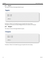
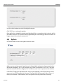
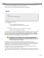
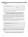
1
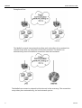
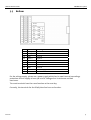
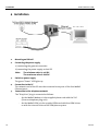
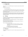
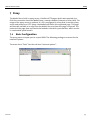
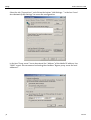
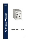
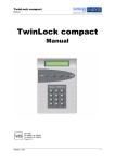
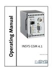
Operating Manual
MoRoS
Modem 1.0
ISDN 1.0
June 06
Copyright © June 06 INSYS MICROELECTRONICS GmbH
Any duplication of this manual is prohibited. All rights on this documentation
and the devices are with INSYS MICROELECTRONICS GmbH Regensburg.
Restrictions of guarantee
This handbook contains a concise description. The compilation of the text has
been performed with utmost care. Despite all efforts, there may be deviations
to the actual functions. No guarantee can therefore be given for the accuracy of
the contents. We can neither assume legal responsibility nor any liability for
incorrect information and their consequences. Suggestions for improvements
and comments are always welcome.
Trademarks and logos
The use of a trademark or logo not shown below does not indicate that it is
freely available for use.
IBM PC, AT, XT are registered trademarks of International Business Machine Corporation.
INSYS ® is a registered trademark of INSYS MICROELECTRONICS GmbH.
Linux is a registered trademark of Linus Torvalds.
Windows™ is a registered trademark of Microsoft Corporation.
Opera is a registered trademark of Opera Software ASA.
Mozilla is a registered trademark of the Mozilla Foundation.
Publisher:
INSYS MICROELECTRONICS GmbH
Waffnergasse 8
93047 Regensburg, Germany
Phone:
0941/560061
Fax:
0941/563471
E-mail:
[email protected]
Internet:
http://www.insys-tec.de
Subject to technical changes. Errors excepted.
Date: June 06
Item number: 31-22-03.056 English
MoRoS Modem/ISDN
Contents
1
SCOPE OF DELIVERY....................................................5
2
GENERAL.....................................................................5
3
DEVICE DESCRIPTION .................................................7
3.1
FRONT PANEL ............................................................................7
3.2
TOP .........................................................................................8
3.3
BOTTOM ..................................................................................9
4
INSTALLATION ..........................................................10
5
CONFIGURATION......................................................11
5.1
PC SETUP ...............................................................................11
5.2
INITIAL CONFIGURATION ...........................................................15
6
FUNCTIONS...............................................................18
6.1
BASIC SETTINGS .......................................................................18
6.2
DHCP ...................................................................................20
6.3
ISDN.....................................................................................21
6.4
MODEM .................................................................................22
6.5
DIAL-IN..................................................................................23
6.6
DIAL-OUT ..............................................................................26
6.7
INPUTS...................................................................................30
6.8
OUTPUTS................................................................................30
June 06
3
Contents
4
MoRoS Modem/ISDN
6.9
SYSTEM ..................................................................................31
7
PROXY ......................................................................35
7.1
BASIC CONFIGURATION.............................................................35
7.2
RELOAD FUNCTION...................................................................37
8
FAQ...........................................................................38
9
SAFETY INSTRUCTIONS.............................................41
10
TECHNICAL DATA......................................................42
10.1
MECHANICAL FEATURES ............................................................42
10.2
POWER SUPPLY .......................................................................42
10.3
INPUTS AND OUTPUTS ..............................................................43
10.4
INTEGRATED SWITCH ................................................................43
10.5
INTEGRATED COMMUNICATION MODULE .....................................43
10.6
INTERFACE COMMUNICATION MODULE .......................................44
10.7
DIRECTIVES .............................................................................45
11
GLOSSARY ................................................................46
June 06
Scope of Delivery
MoRoS Modem/ISDN
1 Scope of Delivery
Before starting with the initial operation, please check if all accessories are
included in the box.
¾
¾
¾
¾
MoRoS
1 phone cord TAE-N at RJ12 (only for MoRoS Modem)
1 ISDN phone cord S0 (only for MoRoS ISDN)
manual
Please contact your supplier if the content is not complete. Please also check the
MoRoS for shipping damage. Please also refer to the supplier if anything is
damaged.
The scope of delivery does not include a power supply.
Please keep the packaging material for possible future shipping or storage.
2 General
The MoRoS is a router with an integrated communication device (analogue
modem or ISDN-TA), and an integrated 4-port switch. It has a very compact design
and a plastic housing according to IP40. The MoRoS has the following
characteristics, which are described in detail in the following:
¾
¾
¾
¾
¾
¾
¾
¾
¾
¾
¾
¾
¾
¾
¾
¾
¾
June 06
integrated configuration interface and help function
easy configuration
local or remote configuration
4-port switch with 10/100 MBit/s
integrated communication module (analogue modem or ISDN-TA)
international country settings (up to 97 countries for the analogue
modem)
dial-In function
dial-Out function
dialing filter for Dial-Out
dial-In authentication for up to 10 users
authentication via PAP, CHAP, MS-CHAP, MS-CHAP 2
DHCP server and client
firmware update (local and remote)
2 digital inputs
2 digital outputs
buffered RTC (real time clock)
proxy server
5
General
MoRoS Modem/ISDN
Examples of Use:
The MoRoS connects two networks to allow each subscriber of one network to
communicate with any subscriber of the other network. The MoRoS can
automatically start to establish a connection from each network.
The MoRoS can connect a network to the Internet in the same way. The connection
setup takes place automatically, via local network queries.
6
June 06
Device Description
MoRoS Modem/ISDN
3 Device Description
3.1
Front panel
The MoRoS has LEDs to indicate the operating state:
Name
Color
LED off
LED on
Power
Green
No supply voltage
Supply voltage available
COM
Green
MoRoS is offline.
MoRoS is hooked to the phone line, but there is no usable
data connection yet (OH).
Orange
MoRoS has established a usable data connection via the
phone line (CONNECT).
Data
Yellow
A PPP data packet is transmitted via the phone line.
Status
Red
MoRoS is ready.
MoRoS is not ready (e.g. after being switched on or when
restoring the standard settings).
1
2
3
4
Green
No LAN cable
connected.
An LAN cable is connected and the port is set to 100 MBit/s.
This LED blinks during data traffic.
June 06
Yellow
An LAN cable is connected and the port is set to 10 MBit/s.
This LED blinks during data traffic.
7
Device Description
MoRoS Modem/ISDN
The reset key has several functions:
¾ Pressing it for a short time (no longer than 1 second) initiates a soft reset. The
MoRoS performs a restart; the integrated communication module is not restarted.
The settings are maintained.
¾ Pressing it for a long time (more than 3 seconds) initiates a hard reset; the
integrated communication module is also restarted. Regarding its effect, this
equals a voltage failure. The settings are maintained.
¾ Pressing the reset key three times for a short time. Each keystroke may not last
longer than 1 second. All three keystrokes must be performed within 2 seconds.
The settings are reset to the factory defaults.
As soon as a function of the reset key becomes active, the “Status” LED lights up red.
The RS232 interface has no function.
3.2
8
Top
Terminal
Meaning
1
OUT 1-NC
Output 1 – normally closed
2
OUT 1
Output 1
3
OUT 1-NO
Output 1 – normally open
4
OUT 2-NC
Output 2 – normally closed
5
OUT 2
Output 2
6
OUT 2-NO
Output 2 – normally open
June 06
Device Description
MoRoS Modem/ISDN
3.3
Bottom
Terminal
Meaning
17
RS 485 B
Reserved
18
RS 485 A
Reserved
19
GND
Ground
20
Input 2
Input 2
21
Input 1
Input 1
22
GND
Ground
23
Reset
Reset input
24
GND
Ground
25
10..60 VDC
Power supply 10V - 60V DC
26
GND
Ground
For the voltage supply, please use a power supply which has its own fuse and overvoltage
protection and can supply at least 3W at a DC voltage of 10 V minimum and 60V
maximum.
The reset terminals have the same function as the reset key.
Currently, the terminals for the RS485 interface have no function.
June 06
9
Installation
MoRoS Modem/ISDN
4 Installation
1.
Mounting on DIN rail
2.
Connecting the power supply
a) connecting the ground connection
b) connecting the power supply 10..60V DC
Note:
3.
The minimum value is 10V DC.
The maximum value is 60V DC.
Switch on power supply
The green ”Power” LED lights up.
4.
Connection to the PC
The network card of the PC must be connected to any one of the four MoRoS
Ethernet ports.
5.
Connection to the telephone network
The ”RJ45/Line” plug is connected as follows:
10
-
for the MoRoS Modem, via the supplied phone cord with the TAE
(German telephone plug unit).
-
for the MoRoS ISDN, via the supplied ISDN cord with the ISDN S0 bus
or with the internal S0 bus of an ISDN phone system.
June 06
Configuration
MoRoS Modem/ISDN
5
Configuration
The configuration of the MoRoS takes place via a network connection between MoRoS
and a PC.
Configuration requirements:
¾ a PC with network card.
¾ an Internet browser (e.g. Mozilla Firefox, Opera, Konqueror or Internet Explorer).
The operating system of the PC is irrelevant for the configuration. The operating system
must support TCP/IP, it must be possible to use the built-in network card, and a web
browser must be installed.
After the configuration is completed, the web interface could also be accessed via a dialup connection. Dial-In must be activated for this action. For the remote configuration,
the notes in the pertinent chapters regarding the individual configuration steps must
absolutely be observed.
5.1
PC Setup
To enable the communication between the PC and the MoRoS, both devices must be
present in the same network. Depending on the operating system, the steps for the
network settings will differ.
The MoRoS has a DHCP server. It is activated by default. The network configuration
should usually take place automatically.
If the automatic configuration doesn't work, the following chapters will help you to
manually configure the network settings.
This is a summary for the PC settings:
1. the IP address must be in the network 192.168.1.X , for example
192.168.1.2; 192.168.1.1 is the IP address of the MoRoS and may
not be used.
2. the network mask must read: 255.255.255.0
3. the gateway address must read: 192.168.1.1
The MoRoS may now be accessed via a browser at the IP address 192.168.1.1.
5.1.1 Windows XP
The Windows XP settings can be accessed via the Explorer (right mouse button on “Start”
-> Explore).
June 06
11
Configuration
MoRoS Modem/ISDN
Under “Control Panel” is located the menu item “Network Connections”. Under this item,
you will find the entry “Local Area Connection”. If this entry is not available yet, it has to
be selected the network installation assistant first to activate the network card.
Right-click on the item “Local Area Connection” to go to “Local Area Connection
Properties”.
12
June 06
MoRoS Modem/ISDN
Configuration
Mark the option ”Internet Protocol (TCP/IP)” and click on “Properties” to go to the
settings to be configured.
Set the IP address in the new window. We recommend entering 192.168.1.2 as the IP
address.
We recommend selecting "Obtain DNS server address automatically" for the DNS setting.
All DNS inquiries which cannot be handled within the local network will be sent to the
MoRoS. If “Dial-Out” was activated, MoRoS will automatically establish a connection, and
will handle the DNS query as soon as this connection is activated.
June 06
13
Configuration
MoRoS Modem/ISDN
If there is already a DNS server in the local network, its IP address can be entered at this
point.
The MoRoS has the IP address 192.168.1.1. This address must be stated as the standard
gateway.
For the sub network mask, the number 255.255.255.0 must be entered.
The DNS server addresses can be entered optionally. It is required if domain names
should be handled.
5.1.2 Windows 2000
The Windows 2000 configuration is almost identical to the Windows XP configuration
described before.
Right-click the “Start” button and then click on “Explore” to open the Explorer. The
network connections are displayed under “System Control“.
Right-click on “Local Area Connections” and afterwards left-click “Properties” to open the
Local Area Connection:
Click on “Internet Protocol (TCP/IP)“ to mark it. One more click on the button “Properties”
will open the next window:
Set the IP address in the new window. We recommend entering 192.168.1.2 as the IP
address.
The factory default IP address of the MoRoS is 192.168.1.1. This address must be stated
as the standard gateway.
We recommend selecting “Obtain DNS server address automatically“ for the DNS setting.
All DNS inquiries which cannot be handled within the local network will be sent to the
MoRoS. If “Dial-Out” was activated, MoRoS will automatically establish a connection, and
will handle the DNS query as soon as this connection is activated.
If there is already a DNS server in the local network, its IP address can be entered at this
point.
For the sub network mask, the number 255.255.255.0 must be entered.
The DNS server addresses can be entered optionally. It is required if domain names
should be handled.
5.1.3 Windows 98
Right-click the “Start” button and then click on “Explore” to open the Explorer. Under
“System Control” you will find the item “Network” on the right side.
Double-click on “Network“ under “System Control“ to display the installed network
protocols.
14
June 06
MoRoS Modem/ISDN
Configuration
Select the protocol “TCP/IP” and click on Properties.
Set the IP addresses on the tab “IP Address“. We recommend entering 192.168.1.2 as the
IP address. The MoRoS has the IP address 192.168.1.1. Enter 255.255.255.0 as sub
network mask.
Enter the IP address of the MoRoS, 192.168.1.1, on the tab "Gateway". This route is
activated after you click “Add”.
Windows 98 must be restarted after all settings are completed.
5.1.4 Linux
A detailed description for the configuration of the IP address in this manual can not be
given. Linux distributors supply different tools. The exact steps for the Ethernet interface
settings are usually explained in the online help or at so-called “Knowledge Portals“, or in
“Forums“ of the according distributor.
The basic steps for the configuration in a shell:
It is assumed that the network interface to be configured has the name “eth0”. This is in
most cases the first (and only) network card in the computer. "Root privileges” for the
configuration are needed.
The command
ifconfig eth0 192.168.1.2
sets the IP address for the network interface eth0 to 192.168.1.2.
The command
route add default gw 192.168.1.1
sets MoRoS as the default gateway.
5.2
Initial Configuration
The configuration interface is displayed via a browser. Enter the URL “http://192.168.1.1”
to access the interface. In this case, the browser “Mozilla Firefox” was used.
Browsers usually provide a button called “Reboot” or “Reload”. Avoid
clicking this button under all circumstances!
To update a page, click on the according button in the content window of the browser.
Alternatively, to confirm the URL in the URL bar the return key may be used as well. This
will reload the MoRoS start page.
June 06
15
Configuration
MoRoS Modem/ISDN
To prevent unauthorized access, the MoRoS provides an access control. The default
settings are as follows:
¾ User name: insys
¾ Password: moros
After successful authentication, the start page of the configuration interface is displayed.
The individual function blocks of the MoRoS can be selected from the buttons on the left
side. Basically, all settings are stored in the device after clicking “OK”. After a restart or a
voltage failure, the MoRoS reloads those settings.
16
June 06
Configuration
MoRoS Modem/ISDN
This is a summary of the possible configuration options of the buttons:
Button
Home
Basic settings
DHCP
Modem or ISDN
Dial-In
Dial-Out
Inputs
Outputs
System
Help
June 06
Configuration
start page, no configuration
authentication, Ethernet addresses DNS
DHCP client, DHCP server
modem or ISDN-TA Configuration, Terminal
on/off, idle time, authentication, IP address, gateway
on/off, phone number, Idle time, authentication, dialing filter
status display, no configuration
status display, opening/closing of contacts
time settings, Restart, Factory defaults, Update, System data
display
help page, no configuration
17
Functions
MoRoS Modem/ISDN
6 Functions
6.1
Basic settings
The access to the settings of the MoRoS is protected from unauthorized access by a
password query. The password is displayed by asterisks.
If the user name and the password can no longer be identified, a device reset of the
MoRoS will reset it to factory defaults. Resetting the device will reset the standard user
name and the standard password to their original state!
When resetting the factory defaults, all settings will be lost, also the set IP
address!
18
June 06
MoRoS Modem/ISDN
Functions
It is mandatory to enter an IP address and a network mask. The IP address is the address
of the MoRoS in the Local Area Network.
After sending the changes to the MoRoS by clicking “OK”, the new addresses
will be valid immediately. This will immediately terminate the connection to
the MoRoS. To be able to continue the configuration, the new IP address
must be entered in the browser window.
The MAC address is unambiguous for each MoRoS. It may not be modified and is unique.
It is merely shown for informational purposes.
The specification of the two IP addresses for a DNS server (Domain Name Service) is
optional.
By default, for one of the two DNS servers, the IP address 127.0.0.1 is entered. MoRoS
itself is no DNS server, but it can forward DNS queries from the connected network to an
external DNS server. To activate forwarding, the IP address 127.0.0.1 must be entered in
at least one of the input fields. For the machines and computers which are connected to
the local network and want to use DNS forwarding by MoRoS, the IP address of the
MoRoS must be entered as DNS server address. By default, this is the IP address
192.168.1.1.
If the MoRoS has “Dial-Out” activated, it will establish a connection to this destination, if
required. After the connection has been established, the MoRoS will often receive one or
two IP addresses for the DNS server. If the target computer specifies DNS servers, the
MoRoS will save those addresses and in the future forward DNS queries to those servers.
If the MoRoS operates as a DHCP server, all DHCP clients will automatically receive the
information about the IP addresses of the set DNS servers during login. If no DNS server
is set, the IP address of an available DNS server must be set for each client.
June 06
19
Functions
MoRoS Modem/ISDN
6.2
DHCP
The MoRoS can be operated as DHCP client or DHCP server.
Only one of the two services may be active simultaneously. Both services may be
deactivated. These settings only apply to the local LAN.
Recommended settings:
¾ If no further network subscribers will be connected to the MoRoS after the initial
installation, the DHCP client as well as the DHCP server should be deactivated. All
network subscribers must be assigned a static IP address. These settings will
ensure that all IP addresses remain unaltered.
¾ If devices must be connected to the network after the initially installed devices,
DHCP server operation is recommended. In this operational mode, it is not
necessary to know the network settings for the connection of new devices such as
a laptop for maintenance purposes. The newly connected devices (DHCP clients)
will automatically be integrated into the network with this new setting. Here,
also, it must be considered that all other network participants must receive static
IP addresses to guarantee accessibility from outside.
MoRoS as DHCP client:
The MoRoS can only be operated as DHCP client, if a DHCP server is operated in the
adjacent Ethernet network. This server will assign an IP address to the MoRoS. If
necessary, the server will assign a new IP address after the lease time has expired (the
lease time is the time that a client is assigned or “leased" an IP address).
When the MoRoS is assigned a new IP address from the DHCP server, the
connection to the MoRoS is terminated. You may only address it via this IP
20
June 06
MoRoS Modem/ISDN
Functions
address from now on. When the MoRoS receives its IP address dynamically as
a DHCP client, you must make sure that its current address is known to the
connected devices as gateway address.
MoRoS as DHCP server:
If the MoRoS is operated as DHCP server, it will assign IP addresses to the connected
network participants which are configured as DHCP clients on request. The MoRoS keeps
its set IP address. When the MoRoS has assigned an IP address to a DHCP client, the lease
times for the assigned IP addresses will be specified in the DHCP configuration.
When operated as DHCP server, connected DHCP clients can only be assigned
new IP addresses after at least half of the Lease Time (1 hour) has expired.
The new address may differ from the old IP address.
Lease Time is the time, after which the MoRoS queries the connected DHCP clients, and
checks if the device still responds after half the time has expired. If the device with that
specific IP address has been replaced (different MAC address), a new IP address will be
assigned. If needed, devices with a static IP address will not be included in the address
distribution by the DHCP server. The DHCP server must be configured in a way that it
doesn't assign addresses from its IP address pool („first IP address“ to „last IP address“),
which haven’t yet been statically set for other devices.
6.3
ISDN
This section describes the configuration of the integrated communication module ISDNTA for the MoRoS ISDN.
The configuration can only take place if neither Dial-In nor Dial-Out is active.
June 06
21
Functions
MoRoS Modem/ISDN
The MoRoS ISDN can be assigned a phone number in the field "MSN" (Multiple Subscriber
Number). From this time on the ISDN-TA can only be reached with this phone number.
Alternatively, "*" may be entered. In this case, the ISDN-TA responds to all incoming calls.
This is the standard setting. This setting, however, may result in problems with other bus
participants at the S0 bus.
Further below, the phone numbers can be set which are permitted to establish a
connection to the MoRoS. The prerequisite is that the phone numbers are transferred
during a call (CLIP). This requires the activation of the according service at the caller's
phone provider. The calling device must communicate its phone number. If this is not the
case, no connection can be established.
AT commands may be entered in the field “Terminal”. This command is sent directly to
the ISDN-TA of the MoRoS. The reply of the ISDN-TA is displayed below the entry field.
6.4
Modem
This section only applies to the MoRoS Modem.
The configuration can only take place if neither Dial-In nor Dial-Out are
active.
22
June 06
MoRoS Modem/ISDN
Functions
The country-specific settings of the modem are loaded in the field “Country code”. Use
the list box to select the required country. The country code is displayed in brackets
behind the country name. The country code may be identical for several countries.
The radio button “Wait for Dialtone” can be set to “Yes” if the modem should wait for a
dial tone before it initiates an outgoing call. It may be necessary to set this setting to
“No”, if the MoRoS is connected to a phone system. It is usually necessary to enter “0” as
dialing code when entering the phone number. Further information about this topic can
be found under "Dial-Out" (Chapter 6.6).
When changing the country code, all standard values for this country setting
are automatically loaded, e.g. “Wait for dial tone” is reset to “No”.
AT commands may be entered in the field “Terminal”. This command is sent directly to
the analogue modem of the MoRoS. The reply of the modem is displayed below the entry
field.
6.5
Dial-In
This setting activates the function “Dial-In”. All other settings are ignored if “No” is
selected at this point.
June 06
23
Functions
MoRoS Modem/ISDN
Enter a value for “Idle time” to set the time after which a Dial-In connection is
automatically terminated, if no data is transmitted during the set time.
The setting “0” will prevent the automatic termination of the connection. In this case, a
connection remains established until the remote terminal terminates the connection.
The maximum number of seconds is 2.147.483.468 (24,85 days).
An automatic termination will only take place when no data is transferred during the
entire set “Idle time”. The time interval is reset and will restart as soon as one single data
packet is transmitted.
The radio button “Authenticate Dial-In” is important if authentication is required for
Dial-In. If “No“ is selected, all persons who know the MoRoS phone number can Dial-In.
This is also the place to set all user names and passwords which should be authorized for
Dial-In. Each user must be assigned the information whether he will login using the
authentications PAP (Password Authentication Protocol) or CHAP (Challenge Handshake
24
June 06
MoRoS Modem/ISDN
Functions
Authentication Protocol). The setting “CHAP” also includes the variants MS-CHAP and
MS-CHAP v2.
After a call is accepted, a PPP (Peer-to-Peer) connection is established. The MoRoS and the
device that performs the Dial-In form an individual network. The MoRoS assigns the IP
address stored above to the remote terminal.
The local IP address of the PPP connection and the IP address of the remote
terminal of the PPP connection must be present in the same network and in
another network than the devices behind the MoRoS.
Example:
IP address and network mask of the MoRoS in the LAN:
192.168.101.xxx / 255.255.255.0
IP address and network mask of the PPP connection of the MoRoS:
192.168.102.xxx / 255.255.255.0
IP address and network mask of the MoRoS in the LAN:
192. 168.103.xxx / 255.255.255.0
In most cases, the suggested addresses may be used.
If the device that is dialing in suggests IP addresses, they are selected from the MoRoS,
independently from the above settings. It must be ensured that the assigned IP address
is present in another network than the devices of the LAN.
If another gateway must be used behind the MoRoS in the LAN, this is the place to enter
the according IP address. One application could be a firewall between MoRoS and the
local network. The incoming data are forwarded to the gateway address during an
existing Dial-In connection. Furthermore, all data packets from devices connected to the
June 06
25
Functions
MoRoS Modem/ISDN
switch are being sent to the gateway. The gateway address is only used for existing DialIn connections.
Click “OK” to store the settings.
6.6
Dial-Out
This setting activates the function “Dial-Out”.
All other settings are ignored if “No” is selected at this point. To enable the MoRoS to
automatically establish a connection, the IP address of the MoRoS must be entered as
standard gateway at the machines which should trigger a connection.
If the MoRoS receives an Ethernet packet from the LAN which is directed to an IP address
outside of the LAN, the MoRoS will start a dial-up connection. The phone number of the
remote terminal must be entered. For connections to the Internet, the phone number of
the ISP (Internet Service Provider) must be entered. The machines and PCs connected to
the switch of the MoRoS must receive the IP address of the MoRoS as standard gateway.
26
June 06
MoRoS Modem/ISDN
Functions
If the MoRoS is connected to a phone system, it may be necessary to enter the prefix “0”
and/or “,” before the phone number.
Enter a value for “Idle time” to set the time after which a Dial-Out connection is
automatically terminated, if no data is transmitted during the set time.
The connection is only then terminated automatically if no data packets are
transmitted during the entire "Idle time". If a data packet is transmitted, the
“Idle timer” starts counting from the beginning.
The setting “0” will prevent the automatic termination of the connection. In this case, a
connection remains established until the remote terminal terminates the connection.
The maximum number of seconds is 2,147,483,648 (24.85 days).
For most dial-up connections, an authentication with the remote terminal is required.
The user name, the password and the authentication type can be set at this point.
Some ISP will not require a user name or a password. If the dial-up to the ISP is not
working although these two fields were left empty, it is possible that the ISP does not
require a particular user name and password, but is waiting for any text in these fields. In
this case, any names can be entered in those fields.
June 06
27
Functions
MoRoS Modem/ISDN
The MoRoS is equipped with a dialing filter which prevents certain data packets to
immediately result in a connection setup and therefore costs. Deactivating the dialing
filter directs each data packet that is aimed at an IP address outside of the LAN to a DialIn at the remote terminal. The dialing rules are that ports are entered in the first table,
and IP addresses are entered in the second table.
Empty fields are also permitted, they will be ignored. Invalid entries (e.g. port 123a3 or IP
address 192.168.1.2000) are automatically ignored and will not be entered into the
configuration.
Ports for the Dial-On-Demand rules:
In the first line, all ports may be entered which are allowed to trigger a dial-up
connection.
In the second line, all ports may be entered which are included in sender packets and
may not trigger a dial-up connection.
Data packets sent to ports in the third row will result in a connection setup.
Data packets sent to ports in the fourth row will not result in a connection setup.
IP addresses for the Dial-On-Demand rules:
In the first line, all IP addresses of the machine may be entered which are allowed to
28
June 06
MoRoS Modem/ISDN
Functions
trigger a dial-up connection.
In the second line, all IP addresses of the machine may be entered which are not allowed
to trigger a dial-up connection.
Data packets sent to the IP addresses in the third line will result in a connection setup.
Data packets sent to IP addresses in the fourth line will not result in a connection setup.
Basically, the following applies:
¾ All rules allowing a connection are linked with “OR”.
¾ All rules not allowing a connection are linked with “AND”.
¾ If at least one line has a value, the rule for this line will come into effect. If no
value is entered, the rule for this line is ignored completely.
For clarification, please find an example with ports: A dial-up connection is established, if
¾ The sender port is specified in a column in the first line
¾ AND is NOT displayed in a column in the second line
¾ OR the sender port is specified in a column in the third line
¾ AND is NOT displayed in a column in the fourth line.
For example, if a port is entered in the third line of the port table, connections to this
destination port will be permitted. This explicit specification will now reject all
connections to other ports. Vice versa applies as well: If a port is entered in the fourth
line, all connections to this port are rejected; data packets at all other ports, however, will
be permitted.
These settings must be considered in combination with each other. Very complex
combinations are possible. It is recommended to test the configuration thoroughly for
logical errors.
Click “OK” to store the above settings.
June 06
29
Functions
6.7
MoRoS Modem/ISDN
Inputs
This shows all states of the digital MoRoS inputs.
The button “Refresh” will reload the page and update the status display.
The inputs can be used to visualize testing the failure of a machine, for example.
6.8
Outputs
This shows all states of the digital MoRoS outputs.
The button “Refresh” will reload the page and update the status display.
30
June 06
MoRoS Modem/ISDN
Functions
Use the radio buttons to switch the digital outputs.
Click "OK" for an automatic update.
One application using this output would be the ability to remotely switch a device within
the LAN on and off. This is often the only possibility for reactivating a device that does no
longer respond to network commands.
6.9
System
Use these fields to enter the system time and date.
Make sure to use the correct input format in these fields; otherwise, the entered values
will not be accepted. “DD” is the calendar day, “MM” is the month, and "JJJJ” is the year
(must be entered with four digits!), “hh” is the hour, and “mm” represents the minutes.
In the field "Time zone" the local time zone may be entered. In this field, the basic time
zones such as UTC (Coordinated Universal Time) or GMT+X (Greenwich Mean Time + X
hours) are available. Furthermore, there are specific country time zones, sorted by
June 06
31
Functions
MoRoS Modem/ISDN
continent (e.g. Europe/Berlin). For the latter, the country-specific time settings will be
considered, such as the daylight savings time in Germany.
The set time for this time zone will be accepted after clicking “OK”.
Two reset types are available:
¾ Hard reset
o by interrupting the supply voltage, or
o by pressing the reset key for more than 3 seconds.
¾ Soft reset
o by pressing the reset key for no longer than 1 second, or
o by reset via the configuration interface.
“OK” will initiate a restart or the loading of the basic settings plus restart. After a restart,
it will take about 25 seconds until the MoRoS is again ready for operation. During the
restart, the “Status” LED on the front panel of the housing lights up red. The MoRoS be
ready for operation after the LED goes out. After the basic settings have been loaded, it
takes about one minute until the MoRoS is ready for operation.
The loading of the basic settings results in all settings being reset to the
factory defaults. This also concerns the user name and the password for the
configuration interface. The IP address and the network mask are also reset
to the factory defaults (see Chapter 6).
Resetting to the basic settings should be avoided when performing a remote
configuration. The loading of the basic settings also means that Dial-Out and Dial-In are
deactivated. It will not be possible afterwards to remotely Dial-In into the MoRoS. The
configuration can then only be performed via a local connection!
The MoRoS can also be restarted by pushing the reset key on the front panel of the
housing for a short time (maximum of 1 second).
The rewriting of the factory settings can also take place via the reset key. Press the reset
key three times for a short time within 2 seconds. Afterwards, the LED “Status” lights up
red.
32
June 06
MoRoS Modem/ISDN
Functions
A software (firmware) update can be performed here.
This function should only be used with the utmost care. Do not perform an
update if it is not absolutely necessary. In case of an error during the update
process it may occur that the MoRoS can not be started afterwards.
Before each update, you must under all circumstances follow the notes of the text file,
which is supplied together with the update file. For some updates, it may be necessary to
load two different files in succession. Afterwards, a restart is often required to load the
new system. Depending on the scope of the system changes due to the new files, the
default settings may need to be restored. The text file supplied together with the update
files will have all the required information.
The update will take place in two steps: First, the new firmware file is loaded into the
nonvolatile memory. The new firmware is then checked for completeness and validity. If
the new file turns out to be invalid or if it has errors, the update will be dismissed. In this
case, the MoRoS will continue working with the previous settings.
If the update file is valid and error-free, the user will again be asked if the system should
be updated with this file. When the user confirms by clicking on "Yes", the system will
finally be overwritten with the new file. After the old system was overwritten with the
new system, no automatic restart is performed. This means that the old system is still
running.
If the update takes place via a dial-up connection, you must see to it that the
connection is not prematurely terminated due to an expired "Idle time".
June 06
33
Functions
MoRoS Modem/ISDN
As the writing of the update may take up to one minute, the values for the “Idle time”
should read "0", because no data is transmitted during the writing process. The system
update will be performed on the remote MoRoS despite a terminated connection. Any
possible messages regarding the success or failure will not be displayed.
If an error took place during the overwriting of the old system, the update procedure
may be repeated.
In no case may the MoRoS perform a restart during an update procedure or
after a failed update! If the reset key is pressed or a voltage failure occurs,
the MoRoS will have no valid system and the device will not be able to start!
A restart of the MoRoS will load the new system. Before a restart is performed, it may be
possible that the basic settings need to be restored first. This information can be taken
from the text file, which is supplied together with the update file.
This field has information regarding the currently running system. These system data as
well as the set IP address should be available if you want to contact the INSYS support.
This field also displays the messages regarding the last ten connections. A successful
connection setup will be recorded with “CONNECT”. If a connection setup was
unsuccessful, the reason why the connection could not be established will be recorded.
34
June 06
MoRoS Modem/ISDN
Proxy
7 Proxy
The MoRoS has a built-in proxy server. It buffers HTTP pages which were queried via a
Dial-Out connection from the MoRoS from a remote network (Internet or other LAN). The
usage of the proxy server is optional. If a PC is configured in a way that it uses the proxy
server and performs a HTTP query, the MoRoS will buffer this requested page. This page
will then be available as a copy from the MoRoS the next time this page is required. The
content of the page does not need to be loaded via the dial-up connection, which results
in a noticeable speed benefit.
7.1
Basic Configuration
The proxy server accepts queries at port 8888. The following settings are meant for the
Internet Explorer:
The menu item “Tools” has the sub item “Internet options”:
June 06
35
Proxy
MoRoS Modem/ISDN
Select the tab “Connections” and click on the button “LAN Settings…” in the box “Local
Area Network (LAN) Settings” to access the configuration.
In the box “Proxy server” has to be entered the “Address” of the MoRoS IP address. Use
“8888” as port. We recommend activating the checkbox “Bypass proxy server for local
addresses”.
36
June 06
MoRoS Modem/ISDN
7.2
Proxy
Reload Function
In case the MoRoS has currently no active dial-up connection and the function “Dial-Out”
is active, a query for a HTTP site will result in the MoRoS establishing a dial-up
connection. For the MoRoS Modem, establishing this connection may take some time,
due to the technology. After some time, the browser will report that the page cannot be
found. Now, it has to be attempted to restart the page using the reload function of the
browser.
To avoid having to use the reload function, the MoRoS comes with an automatism which
automatically retries to send the required data to the browser. For most of the browsers,
this automatism works immediately after the proxy settings are completed.
For the Internet Explorer, one setting must be deactivated to be able to use this
automatism. Re-open the window under “Tools” -> “Internet options”. Remove the
checkmark from the checkbox "Show friendly HTTP error messages" on the tab
"Advanced".
June 06
37
FAQ
MoRoS Modem/ISDN
8 FAQ
In the following some questions are described, which – from experience – may occur
during the installation.
The configuration page of the MoRoS cannot be found. The browser window shows an
error message.
Possible causes:
¾ The network cable between MoRoS and the PC was not properly connected.
¾ The cables for the network and the modem or ISDN were exchanged.
¾ A wrong IP address was entered in the URL bar.
¾ The PC is not in the same network as the MoRoS.
If the MoRoS IP address is unknown, resetting to the factory defaults will result in the
MoRoS being available at the IP address 192.168.1.1 again. Resetting, however, will reset
all settings to the standard values.
If the MoRoS can still not be reached, this means that the PC is in another network than
the MoRoS. In this case, the IP address and the sub network mask of the PC must be
adjusted (see Chapter 5.1).
When no connection with the MoRoS can be established at the initial start-up, the
network card must be checked for the configuration or function.
Dial-Out doesn’t work. A packet which needs to be picked up from another than the local
network, will not result in an established connection. The “DATA” LED will light up green for
a short time and will immediately go out again.
Notes regarding this problem can be found under the menu item “System” of the
configuration surface. The box “System data” lists the last ten messages of the
integrated communication module.
Possible causes:
¾ The configuration has errors. If the MoRoS is located behind a phone system, the
dialing code “0” must possibly be dialed. Some systems require a comma after the
„0“. This will delay the dialing procedure after the zero. It may in addition be
necessary to set the modem settings option“Wait for dialing tone” to “No”.
¾ Blacklisting: The remote terminal cannot establish a PPP connection and
terminates the connection after a call. In this case, the MoRoS will constantly reattempt to establish a connection. After the twelfth unsuccessful attempt, the
integrated communication module is no longer allowed to call this phone
number; the communication module is "blacklisted”. In this case, the MoRoS can
38
June 06
MoRoS Modem/ISDN
FAQ
only try to call this number after 2 hours. The status “blacklisted” can also be
deleted by performing a hard reset (pressing the reset key more than 3 seconds).
No connection between the MoRoS Modem and the MoRoS ISDN can be established.
This is not an error! A connection between analogue connections and ISDN connections
is in general not possible anyways.
A connection to a remote LAN could be established, but a communication with a computer
in the remote LAN is not possible.
Possible causes:
¾ The gateway address of the local computer is wrong.
¾ The DNS resolution is incorrect. This can be checked by using IP addresses instead
of domain names for the communication.
A communication between a local computer and a computer from a remote LAN cannot
be established if all IP addresses are located in the same network. The PPP connection
consists of the two IP addresses of the PPP client and the PPP server. These two addresses
form their own network. This PPP network may also not be the same as the network LAN
1 or LAN 2.
A model distribution of IP addresses in networks with the sub network masks
255.255.255.0:
June 06
39
FAQ
MoRoS Modem/ISDN
The configuration interface acts “funny”: The MoRoS does not accept the interface
configuration.
Possible cause:
¾ After the configuration of a page, the button “Restart” or "Reload” in the browser
was clicked to check if the configuration was accepted.
Please do not click this browser button at any time, as this key does not only update the
content of the current window, but also repeats the entire previous configuration step.
To update the display, the according button in the browser window must be clicked
again.
40
June 06
MoRoS Modem/ISDN
Safety Instructions
9 Safety Instructions
The following instructions must be followed under all circumstances:
¾ All areas that can be opened are maintenance areas. Unauthorized
opening of a maintenance area and inappropriate repairs may
endanger the user.
¾ The MoRoS may not be used in wet environments, damp rooms or
close to water.
¾ Take care not to let liquids seep into the MoRoS as this may lead to
short circuits.
¾ If a power failure occurs the device will not be operational. We
recommend providing a separate circuit for the MoRoS. If other
devices experience short circuits, the MoRoS will thus not be
inoperative.
¾ Using an unsuitable power supply unit could damage the MoRoS; in
this event, the manufacturer will assume no liability.
¾ We recommend installing suitable overvoltage protection.
June 06
41
Technical Data
MoRoS Modem/ISDN
10 Technical Data
10.1 Mechanical Features
MoRoS
Weight
10.58 oz
Dimensions (maximum)
w x d x h = 70 x 110 x 75 mm
Temperature range
32°F..131°F
Protection class
Housing IP 40/ Terminal IP 20
Humidity
0 - 95% non-condensing
10.2 Power Supply
All specified technical data was measured with a nominal input voltage, full load, and an
ambient temperature of 77 °F. The threshold value tolerances are subject to the typical
fluctuations.
To operate the MoRoS, a suitable device protection must be used.
Power supply:
10..60 V DC
Power input:
approx. 3 W (during connection)
Current consumption:
42
Input voltage
Current (closed
circuit)
Current (connection)
10 V DC
200 mA
300 mA
24 V DC
85 mA
125 mA
June 06
MoRoS Modem/ISDN
Technical Data
10.3 Inputs and Outputs
The two digital outputs are potential-free relay switches.
Maximum switch voltage: 30 V (DC) / 42 V (AC)
Maximum current load: 1 A (DC) / 0.5 A (AC)
The digital inputs are designed as pull-up and are on HIGH in inactive, open state. The
inputs are activated by connecting to ground.
LOW 0 .. 1 V
HIGH 4 .. 12 V
The input current from LOW to internal 3.3 V is typically 0.35 mA.
10.4 Integrated Switch
This is a switch, consisting of
¾ 4 ports
¾ 10 / 100 MBit/s for full and half duplex operation (Autosense)
¾ Automatic detection of patch cables/cross over cables
10.5 Integrated Communication Module
Depending on the MoRoS variant, the following can be integrated as communication
module:
¾ Analogue modem, or
¾ ISDN terminal adapter
The analogue modem achieves a maximum data amount of 56kBit/s for connection to
ISPs (Internet Service Providers). For connections into other private LANs, a maximum
data amount of 33.6kBit/s can be achieved. The transmission speed, however, depends
very strongly on the line quality. It may therefore occur that the theoretically achievable
maximum transmission speed is slower.
The integrated communication module of the MoRoS is an i-modul Modem 56k PRO. The
technical data as well as the entire AT command set are summarized in the "Designers
Guide wired” and can be requested free of cost at “www.insys-tec.de”.
An i-modul ISDN-TA+HUT is integrated in the MoRoS ISDN. It achieves a maximum data
amount of 64 kBit/s. In contrast to the analogue modem, this value is fixed. All technical
data regarding this topic are again summarized in the “Designers Guide wired” and may
be obtained from INSYS Microelectronics free of cost.
June 06
43
Technical Data
MoRoS Modem/ISDN
10.6 Interface Communication Module
Phone interface (only for MoRoS Modem).
RJ 12 plug with nose
pointing backwards
E
W
b2 b1
a2 a1
RJ 12 plug front view
Layout of the RJ12 Connector and the RJ45 Jack
Pin
Description
Pin
Description
1
NC (alarm)
4
b1
2
a2
5
b2
3
b1
6
NC (ground)
Meaning of the Signals:
a1, b1: Incoming phone lines (e.g. exchange connection or PBX)
a2, b2: they are used to connect a telephone in series. In idle state, a2
and b2 are connected with a1 and b1 via a loop current
connector. a2 and b2 are disconnected as soon as the modem
occupies the line.
44
June 06
Technical Data
MoRoS Modem/ISDN
S0 interface (only for MoRoS ISDN)
8-pin jack (front view)
Pin
Signal (S0)
1
not connected
2
not connected
3
STA (Transmit A)
4
SRA (Receive A)
5
SRB (Receive B)
6
STB (Transmit B)
7
not connected
8
not connected
Layout of the RJ11 Connector and the RJ45 Jack
10.7 Directives
The MoRoS bears the CE symbol of conformity. This symbol is a declaration that
on account of its design and implementation, the MoRoS is in compliance with
the currently valid versions of the following EC directives:
¾ R&TTE
¾ 89/336/EEC (EMC directive)
¾ 73/23/EEC (Low voltage directive)
¾ 91/263/EEC (Telecommunications devices directive)
¾ CTR 21 (Europe) for MoRoS Modem
¾ CTR 3 (Europe) only for MoRoS Modem
A conformity declaration for the MoRoS may be obtained on request from
[email protected].
June 06
45
Glossary
MoRoS Modem/ISDN
11 Glossary
This describes the most important terms and abbreviations of this manual.
AT command:
Commands to devices such as modems to set up this device.
CHAP:
Challenge Handshake Authentication Protocol; authentication protocol
often used for -> PPP connections.
DHCP:
Dynamic Host Configuration Protocol; DHCP servers can dynamically design
an IP address and other parameters to DHCP clients, on request.
Dial-In:
MoRoS can be called via a Dial-In connection and then create a connection
to the LAN.
Dial-Out:
MoRoS can use a Dial-up to make calls and to perform Internet
connections, for example.
Gateway:
This is a machine that works like a -> Router. In contrast to the router, a
gateway can also route data packets from different hardware networks.
ISP:
Internet Service Provider; an ISP can be called using a dial-up connection
(e.g. with an analogue modem or ISDN-TA). The ISP will then provide access
to the Internet via this dial-up connection.
LAN:
Local Area Network; a network of computers which are located relatively
close to each other.
MAC address:
Media Access Control Address. A MAC is a part of an Ethernet
interface. Each Ethernet interface has a unique global number, the MAC
address.
PAP:
Password Authentication Protocol; an authentication protocol often used
for -> PPP connections.
PPP:
Point to Point Protocol; a protocol, which connects two machines via a
serial line to enable the exchange of TCP/IP packets between those two
machines.
Router:
This is a machine in a network, which is responsible for the incoming data
of a protocol to be forwarded to the planned destination or sub network.
Switch:
A device that can connect several machines with the Ethernet. In contrast
to a hub, a switch will "think” by itself, i.e. it can remember the MAC
addresses connected to a port and directs the traffic more efficiently to the
individual ports.
URL:
“Uniform Resource Locator”; this is the address used by a service to be
found in the web browser. In this manual, an URL is mostly entered as the
IP address of the MoRoS.
WAN:
Wide Area Network; a network consisting of computers, which are located
far away from each other.
46
June 06