1
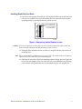
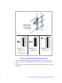
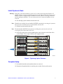
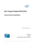
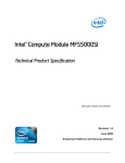
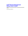
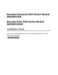
Rail Kit Install Guide: Intel® Modular
Server System MFSYS25
A Guide for Technically Qualified Assemblers of Intel® Identified Subassemblies/
Products
Intel Order Number: E12567-002
Disclaimer
Information in this document is provided in connection with Intel® products. No license, express or implied, by
estoppel or otherwise, to any intellectual property rights is granted by this document. Except as provided in Intel's
Terms and Conditions of Sale for such products, Intel assumes no liability whatsoever, and Intel disclaims any
express or implied warranty, relating to sale and/or use of Intel® products including liability or warranties relating to
fitness for a particular purpose, merchantability, or infringement of any patent, copyright or other intellectual property
right. Intel products are not designed, intended or authorized for use in any medical, life saving, or life sustaining
applications or for any other application in which the failure of the Intel product could create a situation where
personal injury or death may occur. Intel may make changes to specifications and product descriptions at any time,
without notice.
Intel® server boards contain a number of high-density VLSI and power delivery components that need adequate
airflow for cooling. Intel's own chassis are designed and tested to meet the intended thermal requirements of these
components when the fully integrated system is used together. It is the responsibility of the system integrator that
chooses not to use Intel developed server building blocks to consult vendor datasheets and operating parameters to
determine the amount of airflow required for their specific application and environmental conditions. Intel
Corporation can not be held responsible if components fail or the server board does not operate correctly when used
outside any of their published operating or non-operating limits.
Intel, Intel Pentium, and Intel Xeon are trademarks or registered trademarks of Intel Corporation or its subsidiaries in
the United States and other countries.
* Other names and brands may be claimed as the property of others.
Copyright © 2007, Intel Corporation. All Rights Reserved
ii
Rail Kit Install Guide: Intel® Modular Server System MFSYS25
Safety Information
Important Safety Instructions
Read all caution and safety statements in this document before performing any of the
instructions. See also Intel Server Boards and Server Chassis Safety Information on the
Intel® Server Deployment Toolkit CD and/or at http://support.intel.com/support/
motherboards/server/sb/cs-010770.htm.
Wichtige Sicherheitshinweise
Lesen Sie zunächst sämtliche Warnund Sicherheitshinweise in diesem Dokument, bevor
Sie eine der Anweisungen ausführen. Beachten Sie hierzu auch die Sicherheitshinweise zu
Intel-Serverplatinen und Servergehäusen auf der Intel® Server Deployment Toolkit CD
oder unter http://support.intel.com/support/motherboards/server/sb/cs-010770.htm.
Consignes de sécurité
Lisez attention toutes les consignes de sécurité et les mises en garde indiquées dans ce
document avant de suivre toute instruction. Consultez Intel Server Boards and Server
Chassis Safety Information sur le Intel® Server Deployment Toolkit CD ou bien rendezvous sur le site http://support.intel.com/support/motherboards/server/sb/cs-010770.htm.
Instrucciones de seguridad importantes
Lea todas las declaraciones de seguridad y precaución de este documento antes de realizar
cualquiera de las instrucciones. Vea Intel Server Boards and Server Chassis Safety
Information en el Intel® Server Deployment Toolkit CD y/o en http://support.intel.com/
support/motherboards/server/sb/cs-010770.htm.
重要安全指导
Rail Kit Install Guide: Intel® Modular Server System MFSYS25
iii
Warnings
Heed safety instructions: Before working with your server product, whether you are
using this guide or any other resource as a reference, pay close attention to the safety
instructions. You must adhere to the assembly instructions in this guide to ensure and
maintain compliance with existing product certifications and approvals. Use only the
described, regulated components specified in this guide. Use of other products /
components will void the UL listing and other regulatory approvals of the product and
will most likely result in noncompliance with product regulations in the region(s) in which
the product is sold.
System power on/off: The power button DOES NOT turn off the system AC power. To
remove power from system, you must unplug the AC power cord from the wall outlet.
Make sure the AC power cord is unplugged before you open the chassis, add, or remove
any components.
Hazardous conditions, devices and cables: Hazardous electrical conditions may be
present on power, telephone, and communication cables. Turn off the server and
disconnect the power cord, telecommunications systems, networks, and modems attached
to the server before opening it. Otherwise, personal injury or equipment damage can
result.
Electrostatic discharge (ESD) and ESD protection: ESD can damage disk drives,
boards, and other parts. We recommend that you perform all procedures in this chapter
only at an ESD workstation. If one is not available, provide some ESD protection by
wearing an antistatic wrist strap attached to chassis ground any unpainted metal surface on
your server when handling parts.
ESD and handling boards: Always handle boards carefully. They can be extremely
sensitive to ESD. Hold boards only by their edges. After removing a board from its
protective wrapper or from the server, place the board component side up on a grounded,
static free surface. Use a conductive foam pad if available but not the board wrapper. Do
not slide board over any surface.
Installing or removing jumpers: A jumper is a small plastic encased conductor that slips
over two jumper pins. Some jumpers have a small tab on top that you can grip with your
fingertips or with a pair of fine needle nosed pliers. If your jumpers do not have such a
tab, take care when using needle nosed pliers to remove or install a jumper; grip the
narrow sides of the jumper with the pliers, never the wide sides. Gripping the wide sides
can damage the contacts inside the jumper, causing intermittent problems with the
function controlled by that jumper. Take care to grip with, but not squeeze, the pliers or
other tool you use to remove a jumper, or you may bend or break the pins on the board.
iv
Rail Kit Install Guide: Intel® Modular Server System MFSYS25
Contents
Safety Information ..................................................................................................... iii
Important Safety Instructions ................................................................................................ iii
Wichtige Sicherheitshinweise ............................................................................................... iii
Consignes de sécurité .......................................................................................................... iii
Instrucciones de seguridad importantes ............................................................................... iii
Warnings............................................................................................................................... iv
Rail Kit Install Guide ................................................................................................... 1
Kit Contents ........................................................................................................................... 1
Rail Kit Installation Instructions ................................................................................................... 1
Prepare System .......................................................................................................................... 1
Prepare Rack .............................................................................................................................. 2
Install System in Rack ................................................................................................................ 7
Complete Setup .......................................................................................................................... 7
Rail Kit Install Guide: Intel® Modular Server System MFSYS25
v
vi
Rail Kit Install Guide: Intel® Modular Server System MFSYS25
Rail Kit Install Guide
The Intel® Modular Server System MFSYS25 is designed to support cabinets that are 19
inches (483 mm) wide by up to 36 inches (914 mm) deep. A set of rack mounting rails is
provided in this kit and will accommodate either square or round hole rack-mounting
methods.
Kit Contents
Rail Kit Installation Instructions
Rail Kit (AXXMFRAIL)
Item
Quantity
Rail
2
Install Guide
1
Prepare System
Warning: Lifting the system and attaching it to the rack is a three-person operation. Remove all
modules from the system prior to lifting system into rack. This includes all compute server
modules, all power supply modules, all Ethernet switch modules, all storage controllers
and the management module. Use of a mechanical assist is required if modules are not
removed.
1. Read all caution and safety statements listed in this document before performing any
of the steps. See the Intel® Server Boards and Server Chassis Safety Information
document at http://support.intel.com/support/motherboards/server/sb/cs-010770.htm
for a complete listing of all caution and safety statements.
Caution: Before performing any maintenance on the system, back up the data.
2. Turn off all peripheral devices connected to the system. Turn off the system.
3. Disconnect the power cord(s).
Rail Kit Install Guide: Intel® Modular Server System MFSYS25
1
Prepare Rack
Setting the Multi-pin Adapters for Rack Type
The multi-pin adapters allow the rack rails to be used in racks that have either square or
round mounting holes.
Note: The rack rails ship with the multi-pin adapters set for square holes. If your rack has
square mounting holes, skip this section.
4. On each rack rail, reverse the multi-pin adapter position so that it matches the
appropriate rack mounting hole type for your rack.
Round
Square
This side for
rack with
Square Mounting
Holes
This side for
rack with
Round Mounting
Holes
AF002462
Figure 1. Pictorial View of Multi-pin Adapter
2
Rail Kit Install Guide: Intel® Modular Server System MFSYS25
5. To set for round mounting holes, remove the multi-pin adapter by rotating the swivel
lock up (see letter “A” in the following figure). Press and hold the top (floating)
mounting pin downward (see letter “B”) while extracting the middle and bottom pins
from the multi-pin bracket.
B
A
AF002463
Figure 2. Removing Multi-pin Adapter from Multi-pin Bracket
6. Set the multi-pin adapter for round mounting holes (see Figure 1).
Rail Kit Install Guide: Intel® Modular Server System MFSYS25
3
7. Ensure the swivel lock is up (see letter “A” in the following figure). Re-install the
multi-pin adapter into the multi-pin bracket by placing the bottom mounting pin fully
in the bracket. Press and hold the top (floating) pin (see letter “B”) while pushing the
adapter into the bracket. Ensure that all three mounting pins on the multi-pin adapter
are fully engaged in the multi-pin bracket. The multi-pin adapter must be fully locked
into the bracket. Use the swivel lock to lock the multi-pin adapter in place (see letter
“C”).
A
C
B
AF002464
Figure 3. Setting Multi-pin Adapter in Multi-pin Bracket
8. Repeat the previous three steps for both ends of each rack rail.
4
Rail Kit Install Guide: Intel® Modular Server System MFSYS25
Installing Rack Rails into Rack
Hole (or similar mark)
in rack upright identifies
top-most mounting hole
for each 1 RU position
1 RU
1 RU
9. For all four rack uprights, determine the vertical position in the rack at which the rack
rails are to be installed. The top-most mounting hole for a particular rack unit (RU)
mounting position is typically identified by a mark or hole.
AF002465
Figure 4. Determining Vertical Position in Rack
Caution: If rack rail is mounted in holes which are not vertically aligned from front to back, the
rack rail may be damaged and rack mounting will not be secure.
10. Noting the holes determined in the previous step, align the left rack rail with its rear
mounting holes.
Note: Rack rails and multi-pin adapters occupy exactly 3 RU. The lowest point on an adapter is
eight (8) holes lower than the top-most mounting hole.
11. Hold the rack rail in the desired rack-mounting position. Engage the lowest pin in its
hole on the rack upright. At the rear of the rack rail, press and hold the top (floating)
pin downward while pushing the rack rail and adapter into the rack upright holes.
Rail Kit Install Guide: Intel® Modular Server System MFSYS25
5
I
Engage the lowest pin first
in rack upright. Then press
and hold top (floating) pin
downward while inserting
rack rail with adapter into
rack upright mounting
holes.
CORRECT
• Multi-pin adapter pins
are fully engaged in the
rack holes.
INCORRECT
• Multi-pin adapter pins
are not fully engaged in
the rack holes.
INCORRECT
• Top rack hole selected is
not designated top-of-RU
hole.
• Top rack hole selected is
designated top-of-RU hole.
AF002466
Figure 5. Attaching Rack Rail to Multi-pin Bracket
12. Ensure the proper mounting holes on each rack upright are selected. Repeat the
previous step for the front mounting position of the rack rail. Ensure the rack rail is
level.
13. Repeat Steps 10-12 for the right rack rail, ensuring that it is parallel and level with the
left rack rail.
6
Rail Kit Install Guide: Intel® Modular Server System MFSYS25
Install System in Rack
Warning: Lifting the system and attaching it to the rack is a three-person operation. Remove all
modules from the system prior to lifting system into rack. This includes all compute server
modules, all power supply modules, all Ethernet switch modules, all storage controllers
and the management module. Use of a mechanical assist is required if modules are not
removed.
14. Lift and align system with the mounted rack rails.
Note: If handles are installed, the rear handles MUST BE removed prior to setting the system on
the rack rails to avoid interference of the handles with the rack.
15. Slide the system onto the rack rails.
Note: The front handles MUST BE removed prior to sliding the system into the rack and
securing the front chassis tabs to the rack.
16. Secure the system to the rack by tightening the captive fasteners on the front of the
system flanges. These captive fasteners also engage the rails.
AF002467
Figure 6. Tightening Captive Fasteners
Complete Setup
17. Re-install all modules and controllers that were removed.
18. Reconnect all peripheral devices and the power cord(s). Power up the system.
Rail Kit Install Guide: Intel® Modular Server System MFSYS25
7
8
Rail Kit Install Guide: Intel® Modular Server System MFSYS25