1
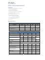
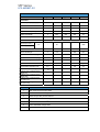
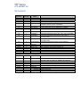
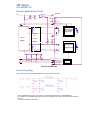
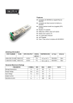
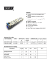
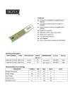
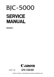
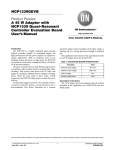
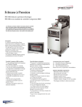
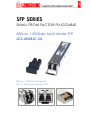
SFP SERIES
SMALL FROM FACTOR PLUGGABLE
850nm 1.25Gbps Multi Mode SFP
LCS-MGBIC-SX
850 nm 1.25Gbps Multi Mode
SFP LC Transceiver Module 3.3V
SFP Series
LCS-MGBIC-SX
850nm 1.25Gbps Multi Mode SFP
Features
.Small From Factor Pluggable MSA compliant.
.For Multi Mode Applications.
.Standard LC Duplex Connector.
.Up to 850 nm & 1.25 Gb/s .
.Compliant for IEEE-802.3z Gigabit Ethernet.
.Power supply : +3.3V.
.EEPROM with serial ID functionality.
.TTL Signal detect indicator.
.PECL input & output logic levels.
.Uncooled VCSEL structure laser.
.0 ~ +70 operating temperature.
.Class 1M laser safety compliance.
23
-10
.2 –1 PRBS, BER=1*10 .
.550 m reach
Specifications
Absolute Maximum Ratings
Parameter
Symbol
Min
Max
Operating temperature
Topr
0
+70
o
C
Storage temperature
Tstg
-40
+85
o
C
-
-
260/10
VccT
-0.5
4
Lead soldering limits
Supply voltage
Unit
o
C/sec
V
Electrical Characteristics
Parameter
Symbol
Min
Typical
Max
Unit
B
-
1250
-
Mb/s
-
1.85
Transmitter:
Data rate (NRZ)
Data PECL Differential input (6)
Vil
V
Vih
2.15
Supply voltage
VCCT
3.1
3.3
3.5
V
Supply current
ICCT
-
130
-
mA
Data rate (NRZ)
B
-
1250
-
Mb/s
Output rise time (10-90%)
tr
-
-
400
ps
Output fall time (10-90%)
tf
-
400
ps
Receiver:
-
VOL
-
-
1.65
V
VOH
2.25
-
-
V
Supply voltage
VCCR
3.1
3.3
3.5
V
Supply current
ICCR
-
120
-
mA
-
2.5
-
dB
Data PECL output (6)
Hysteresis
SFP Series
LCS-MGBIC-SX
Optical Characteristics
Parameter
Symbol
Min
Typical
Max
Unit
Optical output (avg.) (1) (3)
Po
-9.5
-
-4
dBm
Extinction ratio
ER
10
-
-
dB
Output rise time (10-90%)
tr
-
-
400
ps
Output fall time (10-90%)
tf
-
-
400
ps
Optical wavelength
λ
830
850
860
nm
∆λ
-
0.85
-
nm
-
-20
-
-
dBm
Saturation
-
-
-
-3
dBm
Optical wavelength
λ
770
-
860
nm
Signal detect asserted (avg)
PA
-
-
-20
dBm
Signal detect deasserted (avg)
PD
-31
-
-
dBm
Signal Detect-Hysteresis
PA-PD
1.0
-
-
dB
Signal Detect Assert Time
TSD+
-
-
100
Signal Detect Deassert Time
TSD-
-
-
100
µs
µs
VDEF
0.37
-
2.0
V
RX_LOSL
0
-
0.35
V
RX_LOSH
2.4
-
Vcc
V
IARX_LOS
-
-
100
µs
IDRX_LOS
-
-
100
µs
Transmitter:
Spectral width
Receiver:
Optical input (avg.)
sensitivity (1) (5)
PIN
Differential Output Voltage
Receiver Loss of Signal Output
Voltage-low
Receiver Loss of Signal Output
Voltage-High
Receiver Loss of Signal Assert
Time (off to on)
Receiver Loss of Signal Assert
Time (on to off)
Note
1
With 0.275 NA, 62.5/125µm Fiber.
2
Driven with a differential signal
3
Class 1M eye safe per FDA and IEC.
4
Compliant with IEEE 802.3Z Gigabit Ethernet.
5
223 - 1 PRBS, BER= 1*10-10.
6
PECL Differential Voltage Mode.
7
Take normal ESD precautions when handing this product.
SFP Series
LCS-MGBIC-SX
Function Diagram
ELECTRICAL INTERFACE
2
.
RECEIVER
OPTICAL INTERFACE
RX+ (RECEIVE DATA)
AMPLIFCATION
&
QUANTIZATION
INCOMING OPTICAL
SIGNAL
RX- (RECEIVE DATA)
LOSS OF SIGNAL
1
PHOTO DECTOR
TRANSMITTER
TX_DISABLE
LASER DRIVER
& SAFETY
CIRCUITRY
OUTGOING OPTICAL
SIGNAL
TX+ (TRANSMIT DATA)
TX- (TRANSMIT DATA)
TX_FAULT
LASER
MOD – DEF2
EEPROM
MOD – DEF1
MOD – DEF0
Dimensions & Electrical Pin configuration
SFP Series
LCS-MGBIC-SX
SFP to host connector Pin Assignment
AS the LCS-MGBIC-SX is inserted, first contact is made by the housing ground shield,
Discharging any potentially component-damaging static electricity. Ground pins engage next and
are followed by Tx and Rx power supplies. Finally, signal lines are connected. Pin functions and
sequencing are listed in next Table
PINOUT TABLE
Pin
Symbol
Functional Description
1
TGND
Transmit Ground
2
TX_FAULT
Transmit Fault
3
TX_DISABLE
Transmit Disable
4
MOD_DEF(2)
SDA Serial Data Signal
5
MOD_DEF(1)
SCL Serial Clock Signal
6
MOD_DEF(0)
TTL Low
7
RATE SELECT
Open Circuit
8
RX_LOS
Receiver Loss of Signal, TTL High, open collector
9
RGND
Transmitter Ground
10
RGND
Transmitter Ground
11
RGND
Receiver Ground
12
RX-
Receiver Data Bar, Differential PECL, ac coupled
13
RX+
Receiver Data, Differential PECL, ac coupled
14
RGND
Receiver Ground
15
VCCR
Receiver Power Supply
16
VCCT
Transmitter Power Supply
!&
TGND
Transmitter Ground
18
TX+
Transmit Data, Differential PCEL, ac coupled
19
TX+
Transmit Data, Differential PCEL, ac coupled
20
TGND
Transmitter Ground
Tx Disable Characteristics
Input Level (LV-TTL)
Tx Function
Low
High
Non-Connect
ON
OFF
ON
(Disable Pin Truth Table)
SFP Series
LCS-MGBIC-SX
SFP Serial ID
DATA
ADDRESS
LENGTH
(BYTES)
0
1
2
3-10
1
1
1
8
NAME OF
FIELD
Base ID Fields
Identifier
Reserved
Connector
Transceiver
DATA TO BE INCLUDE IN THE FIELD FOR SW
11
12
13
1
1
1
Encoding
BR. Nominal
Reserved
14
1
Length(9µ)-km
Link length supported for 9/125 µm fiber, units of km (00h)
Link length supported for 9/125 µm fiber, units of 100m(00h)
Type of serial transceiver (03h=Transceiver)
Code of optical connector type(07h=LC)
000000012040C00h=1000BASE-SX (Gigabit Ethernet
compliance code for optical compatibility
03h=NRZ Encoding
Nominal baud rate, units of 100MHz(0C=1.25Gbps)
15
1
Length(9µ)
16
1
Length(50µ)
17
1
Length(60µ)
18
1
19
20-35
36-39
40-55
56-59
60-62
63
1
16
4
16
4
3
1
Length(Copper
)
Reserved
Vendor name
SFP vendor name:434F4E41532020202020202020202020h
Vendor OUI
SFP transceiver vendor IEEE company ID
Vendor PN
Part Number
Vendor rev
Revision level for part number
Reserved
CC_BASE
Check code for Base ID Fields( 0 – 62 )
EXTENDED ID FIELDS
64
1
Reserved
65
1
Options
66
67
68-83
84-91
92-94
95
1
1
16
8
3
1
96-127
32
BR. max
BR. min
Vendor SN
Date code
Reserved
CC_EXT
Check code for Extended ID Fields( 64 – 94 )
VENDOR SPECIFIC ID FIELDS
Readable
Vendor specific data, read only
Link length supported for 50/125 µm fiber, units of
10m(37h=550m)
Link length supported for 60/125 µm fiber, units of
10m(1Bh=270m)
Link length supported for copper, units of 10m(00h)
Indicates which optional SFP signals are implemented
(1Ah=RX_LOSS,TX_FAULT,TX_DISABLE all supported
Upper baud rate margin, units of %(00h)
Lower baud rate margin, units of %(00h)
Serial number (ASCII)
Manufacturing date code
SFP Series
LCS-MGBIC-SX
Typical application Circuit
HOUSING
VccT,R
1uF
10uF
0.1uF
1uF
VccT
RES
0.1uF
RES
TX_DISABLE
3
TX_FAULT
TX+
50R
TX+
C
R*
TX-
R
DEPEND
50R
C
PHY OR
SERDES
TX-
VccR
SERDES
10uF
10uF
2
50R
RX-
C
RX+
C
RX-
R*
AMPLIFICATION
&
QUANTIZATION
50R
Vcc T,R
1
VEET
ON
PHY OR
LASER DRIVER
&EYE SAFETY
CIRCUITRY
RX-
1
REF_RATE
RX_LOS
RES
RES
RES
RES
MOD_DEF2
MOD_DEF1
MOD_DEF0
EEPROM
VEER
*NOTE 4.7K<RES<10K
Power Coupling
The L1 and L2 can use Ferrite Bead (BLM11A601S) or inductor (4.7µH)
L1/2 = 1 uH
Value of R5/6/9/10/11/12 may vary as long as proper 50Ω termination or 100Ω differential
Is Provided. For good EMI performance, the power supply filter is required. Use short tracks from the
inductor
L1/2 to the module VccTx/VccRx.
SFP Series
LCS-MGBIC-SX
Qualification Information
SAMPLE
HEADING
TEST
CONDITIONS
REFERENCE
SIZE
Mechanical Shock
5 times/axis
500G , 1.0ms
Vibration
20G , 20Hz - 2000HZ
4min/cycle ,4cycles/axis
Mechanical
Thermal Shock
Delta T=100℃
&
Physical
Solderability
-
Fiber Pull
1Kg ; 3times ; 5sec
Accelerated Aging
85℃ , 5000hrs
High Temperature
85℃ , 2000hrs
Storage
Low Temperature
-40℃ , 2000hrs
Storage
Endurance
Temperature
500 cycles.
Cycling
Cyclic Moisture
10 cycles
Resistance
Damp Heat
40℃ , 95%
RH , 1344hrs
Internal Moisture
Special
Flammability
<5000ppm water vapor
11
11
11
11
11
25
11
11
11
11
11
11
-
-
-
6
Test
ESD Threshold
MIL-STD-883
Method 2002
MIL-STD-883
Method 2007
MIL-STD-883
Method 2003
MIL-STD-883
Method 2007
Bellcore 983
Bellcore 983
Section 5.18
Bellcore 983
Bellcore 983
Bellcore 983
Section 5.20
Bellcore 983
Section 5.23
MIL-STD-202
Method 103
MIL-STD-883
Method 1018
TR357
Sec.4.4.2.5
Bellcore 983
Section 5.22