1
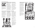
SPECIFICATIONS
Model
Description
Amplifier
Power (RMS)
Peak Dynamic
Power†
L8400P
12" (300mm), 600-Watt, high-performance compact powered subwoofer
600 Watts
1200 Watts
Frequency
Response (–3dB) 22Hz – Low-pass crossover frequency
Low-Pass
Crossover
Frequencies
50Hz – 150Hz, Continuously adjustable
Low-Frequency
Transducer
12" (300mm) PolyPlas™ cone with rubber surround and cast-aluminum chassis;
HeatScape™ motor structure; Symmetrical Field Geometry™ (SFG™); oversized
fiberglass voice coil; magnetic shorting ring
Baffle
Low diffraction, IsoPower™
Enclosure
Sealed
Inputs
Gold-plated 5-way binding-post speaker-level; left and right line-level,
switchable to LFE
Outputs
Gold-plated 5-way binding-post speaker-level; 150Hz high-pass when using
speaker-level connection
Dimensions
(H x W x D)
16-1/2" (15-1/2" without feet) x 15-1/2" x 15-1/2"
(419mm [394mm without feet] x 394mm x 394mm)
Weight
58 lb (26.4kg)
†
The Peak Dynamic Power is measured by recording
the highest peak-to-center voltage produced by the
power amplifier with its limiters disabled, across
the output of a resistive load equal to minimum
impedance of the transducer, using a 50Hz sine wave
burst, 3 cycles on, 17 cycles off.
PRO SOUND COMES HOME™
®
JBL Consumer Products, 250 Crossways Park Drive, Woodbury, NY 11797 USA
8500 Balboa Boulevard, Northridge, CA 91329 USA
2, route de Tours, 72500 Chateau du Loir, France
www.jbl.com
™
STUDIO L SERIES
L8400P
© 2005 Harman International Industries, Incorporated. All rights reserved.
JBL and Harman International are trademarks of Harman International
Industries, Incorporated, registered in the United States and/or other countries.
Part No. 354038-001
Dolby and Pro Logic are registered trademarks of Dolby Laboratories.
DTS is a registered trademark of DTS, Inc.
All features and specifications are subject to change without notice.
OWNER’S GUIDE
READ FIRST! Important Safety Precautions!
1. Read these instructions.
2. Keep these instructions.
3. Heed all warnings.
4. Follow all instructions.
5. Do not use this apparatus near
water.
6. Clean only with a dry cloth.
7. Do not block any ventilation
openings. Install in accordance with
the manufacturer’s instructions.
8. Do not install near any heat
sources such as radiators, heat registers, stoves or other apparatus
(including amplifiers) that produce
heat.
9. Do not defeat the safety purpose
of the polarized or grounding-type
plug. A polarized plug has two
blades with one wider than the
other. A grounding-type plug has
two blades and a third grounding
prong. The wide blade or the third
prong are provided for your safety.
If the provided plug does not fit into
your outlet, consult an electrician
for replacement of the obsolete
outlet.
10. Protect the power cord from
being walked on or pinched, particularly at plugs, convenience receptacles and the point where they exit
from the apparatus.
11. Only use attachments/accessories specified by the manufacturer.
12. Use only with the cart,
stand, tripod, bracket or
table specified by the
manufacturer or sold
with the apparatus.
When a cart is used, use
caution when moving the cart/apparatus combination to avoid injury
from tip-over.
2
13. Unplug this apparatus during
lightning storms or when unused for
long periods of time.
14. Refer all servicing to qualified
service personnel. Servicing is
required when the apparatus has
been damaged in any way, such
as power-supply cord or plug is
damaged, liquid has been spilled
or objects have fallen into the
apparatus, the apparatus has been
exposed to rain or moisture, does
not operate normally, or has been
dropped.
15. Do not use attachments not
recommended by the product
manufacturer, as they may cause
hazards.
16. This product should be operated
only from the type of power source
indicated on the marking label. If
you are not sure of the type of
power supply to your home, consult
your product dealer or local power
company. For products intended to
operate from battery power, or other
sources, refer to the operating
instructions.
17. If an outside antenna or cable
system is connected to the product,
be sure the antenna or cable system is grounded so as to provide
some protection against voltage
surges and built-up static charges.
Article 810 of the National Electrical
Code, ANSI/NFPA 70, provides
information with regard to proper
grounding of the mast and supporting structure, grounding of the leadin wire to an antenna discharge
unit, size of grounding conductors,
location of antenna-discharge unit,
connection to grounding electrodes,
and requirements for the grounding
electrode. See Figure A.
18. An outside antenna system
should not be located in the vicinity
of overhead power lines or other
electric light or power circuits, or
where it can fall into such power
Figure A.
Example of Antenna Grounding as
per National Electrical Code,
ANSI/NFPA 70
lines or circuits. When installing an
outside antenna system, extreme
care should be taken to keep from
touching such power lines or circuits, as contact with them might
be fatal.
19. Do not overload wall outlets,
extension cords, or integral
convenience receptacles, as this
can result in a risk of fire or
electric shock.
20. Never push objects of any kind
into this product through openings,
as they may touch dangerous voltage points or short-out parts that
could result in a fire or electric
shock. Never spill liquid of any kind
on the product.
21. The apparatus shall not be
exposed to dripping or splashing,
and no objects filled with liquids,
such as vases, shall be placed on
the apparatus.
22. Do not attempt to service this
product yourself, as opening or
removing covers may expose you to
dangerous voltage or other hazards.
Refer all servicing to qualified service personnel.
23. When replacement parts are
required, be sure the service technician has used replacement parts
specified by the manufacturer or
that have the same characteristics
as the original part. Unauthorized
substitutions may result in fire, electric shock or other hazards.
24. Upon completion of any service
or repairs to this product, ask the
service technician to perform safety
checks to determine that the product is in proper operating condition.
25. The product should be mounted
to a wall or ceiling only as recommended by the manufacturer.
THANK YOU FOR CHOOSING JBL
For more than 50 years, JBL
has been involved in every
aspect of music and film
recording and reproduction,
from live performances to the
recordings you play in your
home, car or office.
provide every note of enjoyment that you expected – and
that when you think about
purchasing additional audio
equipment for your home, car
or office, you will once again
choose JBL.
site at www.jbl.com. This
enables us to keep you posted
on our latest advancements,
and helps us to better understand our customers and build
products that meet their needs
and expectations.
We’re confident that the JBL
system you have chosen will
Please take a moment to register your product on our Web
JBL Consumer Products
SPEAKER PLACEMENT
• As a general rule, bass
response increases as a
subwoofer is placed closer
to a wall. Therefore, bass
output is maximized when
the subwoofer is placed in a
corner.
• It is also recommended that
the subwoofer be positioned
along the same wall as the
front loudspeakers.
Low-frequency sounds are normally omnidirectional, meaning
the listener can’t tell where they
are generated from. However,
frequencies between 75Hz and
150Hz can be localized, especially at higher volume levels.
Positioning your subwoofer as
recommended will provide the
most natural soundstage and
imaging from your loudspeaker
system.
Remember that these are just
guidelines. Since every listening
room is different, JBL strongly
recommends experimenting
with the positioning of your
subwoofer to obtain the most
pleasing results in your room.
One technique that can help
you find the ideal subwoofer
location is to temporarily place
the subwoofer near the main
listening location. Then move
around the room and determine
where you hear the most
pleasing bass performance.
This would then be the ideal
location for the subwoofer.
SPEAKER CONNECTION
When we designed the L8400P
powered subwoofer, our goal
was to offer the user the best
possible performance combined with the most flexible
and complete installation
options. Please look over the
following three examples to
determine which description
best matches your system and
follow the corresponding
hookup instructions.
To use the binding-post
speaker terminals with bare
wire, unscrew the collar until
the hole through the center
post is visible under the collar.
Insert the bare end of the wire
through the hole in the post,
then screw the collar back
down until the connection is
tight. The holes in the center
of the collars are intended for
banana-type connectors. To
comply with European CE
certification, these holes are
blocked with plastic inserts at
the point of manufacture. To
use banana-type connectors
requires the removal of the
inserts. Do not remove these
inserts if you are using the
product in an area covered by
the European CE certification.
Speakers and electronics
have corresponding positive
(+) and negative (–) terminals.
It is important to connect both
speakers identically: positive
(+) on the speaker to positive
(+) on the amplifier and negative (–) on the speaker to
negative (–) on the amplifier.
Wiring “out of phase” results
in thin sound, weak bass and
a poor stereo image.
With the advent of multichannel surround sound systems,
connecting all of the speakers
in your system with the correct polarity remains equally
important in order to preserve
the proper ambience and
directionality of the program
material.
3
DOLBY® DIGITAL OR DTS®
(OR OTHER DIGITAL SURROUND MODE) CONNECTION
Use this installation method for
Dolby Digital, DTS or other digital surround processors:
Use either the left or right linelevel input jack for the LowFrequency Effects channel; it
doesn’t matter which one you
choose.
IMPORTANT: Make sure that
the LFE/Normal toggle switch
∞ is in the “LFE” position.
This will bypass the subwoofer’s normal low-pass
filter, reducing the possibility
of signal degradation and more
accurately reproducing the
program materials. However, if
your receiver is passing a fullrange signal through its subwoofer output, place the toggle switch in the “Normal”
position, which will activate
the low-pass filter and protect
the subwoofer from possible
damage. Connect this jack to
the LFE output or subwoofer
output on your receiver or
amplifier. Connect each
speaker to the corresponding
speaker terminals on your
receiver or amplifier.
Make sure that you have configured your surround sound
processor for “Subwoofer On.”
Also, remember to configure
your receiver for 5.1-, 6.1- or
7.1-channel operation as
appropriate.
DOLBY PRO LOGIC® (NON-DIGITAL) – LINE LEVEL
Use this installation method
for Dolby Pro Logic applications (not Dolby Digital, DTS
or other digital processing),
where the receiver/processor
is equipped with a subwoofer
output, or a volume-controlled
preamp (line-) level output:
Use RCA-type interconnects
to connect the line-level
subwoofer outputs on your
receiver or amplifier to the
line-level inputs on the sub-
woofer. IMPORTANT: Make
sure that the LFE/Normal
toggle switch ∞ is in the
“Normal” position. This will
activate the subwoofer’s lowpass filter, protecting the subwoofer from possible damage
and enabling it to operate most
efficiently by reproducing only
the low-frequency materials
that it is best at handling.
NOTE: If your receiver or
amplifier only has one sub-
woofer output jack, then you
will need to use a Y-connector
(not included). Plug the male
end of the Y-connector into
your receiver or amplifier’s
subwoofer output jack, and
connect each of the two
female ends to separate RCAtype interconnects. Finally,
plug the RCA-type interconnects into the line-level inputs
on the subwoofer.
DOLBY PRO LOGIC (NON-DIGITAL) – SPEAKER LEVEL
Use this installation method
for Dolby Pro Logic applications (not Dolby Digital, DTS
or other digital processing),
where the receiver/processor
does not have a subwoofer
output, or a volume-controlled
preamp (line-) level output:
Connect your receiver or
amplifier’s front left and right
speaker terminals to the left
and right terminals on the
subwoofer that are marked
“Speaker Level In.” Connect
the left and right terminals
on the subwoofer that are
marked “Speaker Level Out” to
the corresponding terminals on
the back of your front left and
right speakers.
Connect your receiver or
amplifier’s center, surround
and surround back speaker
terminals to the corresponding
terminals on the back of
your center and surround
speakers.
Connect each speaker to
the corresponding speaker
terminals on your receiver
or amplifier.
Make sure your receiver or
processor is correctly configured to indicate that the subwoofer is “On.”
Note for advanced users: If
your receiver/processor has
a built-in low-pass crossover
filter for the subwoofer output,
you may switch the LFE/
Normal toggle switch to the
“LFE” position to bypass the
subwoofer’s internal
crossover.
4
5
OPERATION
Phase Control
Power
Move the Master Power switch
¢ to the “On” position to use
the L8400P subwoofer.
If you will be away from home
for an extended period of time,
or if the subwoofer will not be
used, switch the Master
Power switch ¢ to the “Off”
position.
adjustment depends on several variables such as room
size, subwoofer placement,
type of main speakers and
position. Adjust the subwoofer
level so that the volume of the
bass information is pleasing
to you.
Level Control
The subwoofer Level Control
• adjusts the volume of the
subwoofer relative to the rest
of the system. Proper level
The Phase Control § determines whether the subwoofer’s pistonlike action
moves in and out in phase
with the main speakers or
opposite the main speakers.
There is no correct or incorrect setting. Proper phase
adjustment depends on several variables such as subwoofer placement and listener position. Adjust the
Phase switch to maximize
bass output at the listening
position.
Remember, every system,
room and listener is different.
There are no right or wrong
settings; this switch offers the
added flexibility to adjust your
subwoofer for optimum performance for your specific
listening conditions without
having to move your speakers.
If at some time in the future
you happen to rearrange your
listening room and move your
speakers, you should experiment with the Phase switch in
both positions, and leave it in
the position that maximizes
bass performance.
TROUBLESHOOTING
Crossover Adjustments
The Crossover Frequency
Control ¶ determines the
highest frequency at which the
subwoofer reproduces sounds.
If your main speakers can
comfortably reproduce some
low-frequency sounds, set this
control to a lower frequency
setting, between 50Hz and
100Hz. This will concentrate
the subwoofer’s efforts on
the ultradeep bass sounds
required by today’s films and
music. If you are using smaller
bookshelf speakers that do not
extend to the lower bass frequencies, set the low-pass
crossover control to a higher
setting, between 120Hz and
150Hz. This control is not used
when the LFE switch ∞ is in
the “LFE” position.
If you used the high-level
(speaker) inputs and there
is no sound from any of the
speakers:
• Check that the receiver/
amplifier is on and a source
is playing.
• Check that the powered
subwoofer is plugged into
an active electrical outlet
and is switched on.
• Check all wires and connections between the receiver/
amplifier and the speakers.
Make sure all wires are connected. Make sure none of
the speaker wires are frayed,
cut or punctured, or touching
each other.
• Review proper operation
of your receiver/amplifier.
If there is low (or no) bass
output:
If you used the line-level
inputs and there is no sound
from the subwoofer:
• Make sure the connections
to the left and right “Speaker
Inputs” have the correct
polarity (+ and –).
• Check that the receiver/
amplifier is on and a source is
playing.
• Make sure that the subwoofer is plugged into an
active electrical outlet and
switched on.
• Check that the powered
subwoofer is plugged into an
active electrical outlet and is
switched on.
• Adjust the crossover point.
• Check all wires and
connections between the
receiver/amplifier and the
subwoofer. Make sure all
wires are connected. Make
sure none of the wires are
frayed, cut or punctured, or
touching each other.
• Flip the Phase Control switch
to the opposite position.
• If you are using a Dolby
Digital/DTS receiver or
processor, make sure that the
subwoofer and bass management adjustments on the
receiver/processor are set up
correctly.
• Slowly turn the Level Control
clockwise until you begin to
hear the desired amount of
bass.
• Review proper operation of
your receiver/amplifier.
• Slowly turn the Level
Control clockwise until you
begin to hear the desired
amount of bass.
• Make sure that you have
configured your receiver/
processor so that the subwoofer/LFE output is on.
6
7