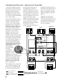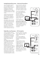
1
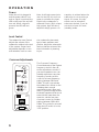
®
™
NORTHRIDGE E SERIES
E150P, E250P
OWNER’S GUIDE
READ FIRST!
Important Safety Precautions!
CAUTION
RISK OF ELECTRIC SHOCK
DO NOT OPEN
CAUTION: To reduce the risk of electric shock,
do not remove cover (or back).
No user-serviceable parts inside.
Refer servicing to qualified service personnel.
CAUTION: To prevent electric shock,
do not use this (polarized) plug with
an extension cord, receptacle or other outlet
unless the blades can be fully inserted to
prevent blade exposure.
The lightning flash with arrowhead symbol,
within an equilateral triangle, is intended to
alert the user to the presence of uninsulated
“dangerous voltage” within the product’s
enclosure that may be of sufficient magnitude to constitute
a risk of electric shock to persons.
The exclamation point within an equilateral
triangle is intended to alert the user to the
presence of important operating and
maintenance (servicing) instructions in the
literature accompanying the appliance.
1. Read these instructions.
2. Keep these instructions.
3. Heed all warnings.
4. Follow all instructions.
5. Do not use this apparatus near
water.
6. Clean only with a dry cloth.
7. Do not block any ventilation
openings. Install in accordance
with the manufacturer’s
instructions.
8. Do not install near any heat
sources such as radiators, heat
registers, stoves or other apparatus (including amplifiers) that
produce heat.
9. Do not defeat the safety purpose
of the polarized or grounding-type
plug. A polarized plug has two
blades with one wider than the
other. A grounding-type plug has
two blades and a third grounding
prong. The wide blade or the third
prong are provided for your safety.
If the provided plug does not
fit into your outlet, consult an
electrician for replacement of the
obsolete outlet.
10. Protect the power cord from
being walked on or pinched, particularly at plugs, convenience
receptacles and the point where
they exit from the apparatus.
11. Only use attachments/
accessories specified by the
manufacturer.
12. Use only with the cart,
stand, tripod, bracket or
table specified by the
manufacturer or sold
with the apparatus.
2
When a cart is used, use caution
when moving the cart/apparatus
combination to avoid injury from
tip-over.
13. Unplug this apparatus during
lightning storms or when unused
for long periods of time.
14. Refer all servicing to qualified
service personnel. Servicing is
required when the apparatus has
been damaged in any way, such as
power-supply cord or plug is damaged, liquid has been spilled or
objects have fallen into the apparatus, the apparatus has been
exposed to rain or moisture, does
not operate normally, or has been
dropped.
15. Do not use attachments not
recommended by the product
manufacturer, as they may cause
hazards.
16. This product should be operated only from the type of power
source indicated on the marking
label. If you are not sure of the
type of power supply to your home,
consult your product dealer or
local power company. For products intended to operate from battery power, or other sources, refer
to the operating instructions.
17. If an outside antenna or cable
system is connected to the product, be sure the antenna or cable
system is grounded so as to provide some protection against voltage surges and built-up static
charges. Article 810 of the
National Electrical Code, ANSI/
NFPA 70, provides information with
regard to proper grounding of the
mast and supporting structure,
grounding of the lead-in wire to
an antenna discharge unit, size of
grounding conductors, location of
antenna-discharge unit, connection to grounding electrodes, and
requirements for the grounding
electrode. See Figure A.
18. An outside antenna system
should not be located in the vicinity of overhead power lines or
other electric light or power circuits, or where it can fall into such
power lines or circuits. When
installing an outside antenna system, extreme care should be taken
to keep from touching such power
lines or circuits, as contact with
them might be fatal.
19. Do not overload wall outlets,
extension cords, or integral convenience receptacles, as this can
result in a risk of fire or electric
shock.
20. Never push objects of any kind
into this product through openings,
as they may touch dangerous voltage points or short-out parts that
could result in a fire or electric
shock. Never spill liquid of any
kind on the product.
21. Do not attempt to service this
product yourself, as opening or
removing covers may expose you
to dangerous voltage or other hazards. Refer all servicing to qualified service personnel.
22. When replacement parts are
required, be sure the service technician has used replacement parts
specified by the manufacturer or
that have the same characteristics
as the original part. Unauthorized
substitutions may result in fire,
electric shock or other hazards.
23. Upon completion of any service
or repairs to this product, ask the
service technician to perform
safety checks to determine that
the product is in proper operating
condition.
24. The product should be mounted
to a wall or ceiling only as recommended by the manufacturer.
Figure A.
Example of Antenna Grounding as
per National Electrical Code,
ANSI/NFPA 70
Antenna Lead-In Wire
Ground Clamp
Antenna Discharge Unit (NEC Section 810-20)
Grounding Conductors (NEC Section 810-21)
Electric Service Equipment
Ground Clamps
Power Service Grounding Electrode System
(NEC Art 250, Part H)
THANK YOU FOR CHOOSING JBL
For more than 50 years, JBL
has been involved in every
aspect of music and film
recording and reproduction,
from live performances to
the recordings you play in
your home, car or office.
provide every note of enjoyment that you expected –
and that when you think
about purchasing additional
audio equipment for your
home, car or office, you will
once again choose JBL.
We’re confident that the JBL
system you have chosen will
Please take a moment to
register your product on our
Web site at www.jbl.com.
This enables us to keep you
posted on our latest advancements, and helps us to better
understand our customers
and build products that
meet their needs and
expectations.
JBL Consumer Products
SPEAKER PLACEMENT
• As a general rule, bass
response increases as a
subwoofer is placed closer
to a wall. Therefore, bass
output is maximized when
the subwoofer is placed in a
corner.
• It is also recommended that
the subwoofer be positioned
along the same wall as the
front loudspeakers.
Low-frequency sounds are normally omnidirectional, meaning
the listener can’t tell where they
are generated from. However,
frequencies between 75Hz and
150Hz can be localized, especially at higher volume levels.
Positioning your subwoofer as
recommended will provide the
most natural soundstage and
imaging from your loudspeaker
system.
Remember that these are just
guidelines. Since every listening
room is different, JBL strongly
recommends experimenting
with the positioning of your
subwoofer to obtain the most
pleasing results in your room.
One technique that can help
you find the ideal subwoofer
location is to temporarily place
the subwoofer near the main
listening location. Then move
around the room and determine
where you hear the most
pleasing bass performance.
This would then be the ideal
location for the subwoofer.
SPEAKER CONNECTION
When we designed the
E150P and E250P powered
subwoofers, our goal was
to offer the user the best possible performance combined
with the most flexible and
complete installation options.
Please look over the following
three examples to determine
which description best
matches your system and
follow the corresponding
hookup instructions.
To use the binding-post
speaker terminals with bare
wire, unscrew the collar until
the hole through the center
post is visible under the collar.
Insert the bare end of the wire
through the hole in the post,
then screw the collar back
down until the connection is
tight. The holes in the center
of the collars are intended for
banana-type connectors.
Speakers and electronics terminals have corresponding positive
(+) and negative (–) terminals. It
is important to connect both
speakers identically:
positive (+) on the speaker
to positive (+) on the amplifier
and negative (–) on the speaker
to negative (–) on the amplifier.
Wiring “out of phase” results in
thin sound, weak bass and a
poor stereo image.
NOTE: The speaker-level connection method described on
page 4 is not a preferred connection and should only be
resorted to if your receiver/
processor does not have a
line-level or subwoofer output.
The customer is responsible for
proper connections, and any
damage to JBL or other equipment due to improper connections will not be covered by
your JBL warranty. Consult with
your JBL dealer or an audioinstallation expert if you have
any questions about how to
connect your subwoofer using
the speaker-level inputs.
3
Analog Receiver/Processor – Speaker-Level Connections
Use this installation method
only with an analog receiver/
processor that does not have
digital processing or bass
management, and also does
not have a subwoofer output
or a volume-controlled preamp
(line-) level output:
Connect the speaker wires for
both your main left and right
speakers, and for the subwoofer, to the same speaker
terminals on your receiver or
amplifier. The wires may be
joined by twisting together the
bare ends of the two leads
that will be connected to each
terminal on the receiver/
amplifier, as shown in the
diagram. This procedure
should be done only four times
(involving a total of eight barewire ends), and only for those
wire ends that are being connected to the terminals on
your receiver/amplifier. It is
important that you avoid joining any other wires. Do not
twist together
wire ends that
are being
inserted into
terminals on any
speaker or on the
subwoofer. Do not twist
together wire ends that will be
used for any speakers other
than the front left and right
speakers or the subwoofer.
Refer to the connection diagram for guidance.
Twist together the (+) leads at
one end of the speaker wires
that you have designated for
the left front speaker and for
To (+) terminal on
left speaker
To (+) terminal of left
input on subwoofer
4
the left high-level inputs on
the subwoofer. Insert the
joined (twisted) wires into the
left front (+) terminal on your
receiver/amplifier. Connect the
free end of the (+) lead for the
left front speaker to the (+) terminal on the back of the
speaker. Connect the free end
of the (+) lead for the left input
on the subwoofer to the left
binding-post terminal. Repeat
this process for the (–)
connections for the left front
speaker and left input on the
subwoofer, and then for the (+)
and (–) connections for the
right front speaker and right
high-level inputs on the subwoofer.
Connect your receiver or
amplifier’s center and surround speaker terminals to the
corresponding terminals on
the back of your center and
surround speakers.
Left Front
+
Right Front
Center
–
+
+
–
–
Subwoofer
L
HIGH
LEVEL
IN
+
R
–
Receiver
Left Front
+
Right Front
Center
–
+
Twist
Here
–
+
Twist
Here
Left Surround
+
Right Surround
–
+
Left Surround
+
–
–
Right Surround
–
+
To front left
(+) terminal on
receiver/amplifier
–
Analog Receiver/Processor – Line-Level Connections
Use this installation method
with an analog receiver/
processor that does not have
digital processing or bass
management, and that is
equipped with a full-range
subwoofer output or a volumecontrolled preamp (line-) level
output:
Use RCA-type interconnect
cables to connect the linelevel subwoofer outputs on
your receiver or amplifier to
the line-level inputs on the
subwoofer.
IMPORTANT: Make sure that
the LFE toggle switch on the
subwoofer is in the “Normal”
position. Do not use the
“LFE” position with Dolby*
Pro Logic*-only processors.
Note: If your receiver or
amplifier has only one subwoofer output jack, then you
may connect the subwoofer
output on your receiver/preamplifier to either the left or
right line-level input on the
subwoofer. It makes no difference which jack you choose.
LEVEL
Make sure your receiver
or processor is configured so that the subwoofer is “On.”
Max
Min
LFE
Connect each speaker to
the corresponding speaker
terminals on your
receiver or amplifier.
PHASE
NORMAL
0º
180º
CROSSOVER
FREQUENCY
RECEIVER
150Hz
50Hz
Subwoofer
Out
L
R
Note for advanced
users: If your receiver/
processor has a built-in lowpass crossover filter for the
subwoofer output, then the LFE
switch should be set to the
“LFE” position to bypass the
subwoofer’s internal
crossover.
L
R
LINE LEVEL IN
For LFE use L or R
L
HIGH
LEVEL
IN
R
+ –
Digital Receiver/Processor – LFE Connection
Use this installation method
for Dolby Digital, DTS® or other
digital surround processors
that have bass-management
programming, or for analog
receivers/processors that
have a filtered subwoofer
output:
the left or right line-level input
on the subwoofer. It makes no
difference which jack you
choose.
IMPORTANT: Make sure that
the LFE toggle switch on the
subwoofer is in the “LFE”
position. Use the line-level
input jacks for the LowFrequency Effects channel.
Connect these jacks to the LFE
output or subwoofer output on
your receiver or amplifier.
Make sure that you have
configured your surround
sound processor for RECEIVER/PREAMPLIFIER
“Subwoofer On” or
Subwoofer
Output/LFE
“LFE On.” The front,
center and surround
speakers should be
set to “Small” or “Large”
depending on their size and
frequency response. Consult
your receiver’s or processor’s
owner’s manual.
Note: If your receiver or amplifier has only one subwoofer
output jack, you may connect
the subwoofer output on your
receiver/preamplifier to either
LEVEL
Connect each speaker to
the corresponding speaker
terminals on your receiver or
amplifier.
Max
Min
LFE
PHASE
NORMAL
0º
180º
CROSSOVER
FREQUENCY
150Hz
50Hz
L
R
LINE LEVEL IN
For LFE use L or R
L
HIGH
LEVEL
IN
+ –
R
5
OPERATION
Power
When the unit is plugged in
and the power switch is on
and no signal is received, the
LED on the top of the unit will
turn red. When a signal is
present, the LED will turn
green.
Note: It will take several minutes for the LED to turn from
green to red after the input
signal to the subwoofer is
removed. Due to JBL’s unique
high-output, high-efficiency
amplifier design, power con-
Level Control
The subwoofer Level Control
adjusts the volume of the
subwoofer relative to the rest
of the system. Proper level
adjustment depends on several variables such as room
size, subwoofer placement,
type of main speakers and
position. Adjust the subwoofer
level so that the volume of the
bass information is pleasing
to you.
Crossover Adjustments
LEVEL
Max
Min
LFE
PHASE
NORMAL
0º
180º
CROSSOVER
FREQUENCY
150Hz
50Hz
L
R
LINE LEVEL IN
For LFE use L or R
L
HIGH
LEVEL
IN
+ –
ON
OFF
POWER
R
120V
60Hz
Northridge E Series
CAUTION
RISK OF ELECTRIC SHOCK
DO NOT OPEN
6
The Crossover Frequency
Control determines the highest
frequency at which the subwoofer reproduces sounds. If
your main speakers can comfortably reproduce some lowfrequency sounds, set this
control to a lower frequency
setting, between 50Hz and
100Hz. This will concentrate
the subwoofer’s efforts on the
ultradeep bass sounds
required by today’s films and
music. If you are using smaller
bookshelf speakers that do not
extend to the lower bass frequencies, set the low-pass
crossover control to a higher
setting, between 120Hz and
150Hz. This control is not used
when the LFE switch is in the
“LFE” position.
sumption is minimal when the
subwoofer is not receiving a
signal. Of course, the subwoofer can be turned off,
whenever desired, if you do
not wish to leave it in auto
(standby) mode.
Phase Control
The Phase Control determines
whether the subwoofer’s piston-like action moves in and
out in phase with the main
speakers or opposite the
main speakers. There is no
correct or incorrect setting.
Proper phase adjustment
depends on several variables
such as subwoofer placement
and listener position. Adjust
the phase switch to maximize
bass output at the listening
position.
Remember, every system,
room and listener is different.
There are no right or wrong
settings; this switch offers the
added flexibility to adjust your
subwoofer for optimum performance for your specific
listening conditions without
having to move your speakers.
If at some time in the future
you happen to rearrange your
listening room and move your
speakers, you should experiment with the phase switch in
both positions, and leave it in
the position that maximizes
bass performance.
TROUBLESHOOTING
If you used the high-level
(speaker) inputs and there
is no sound from any of the
speakers:
• Check that the receiver/
amplifier is on and a source
is playing.
• Check that the powered
subwoofer is plugged into
an active electrical outlet
and is switched on.
• Check all wires and connections between the receiver/
amplifier and the speakers.
Make sure all wires are connected. Make sure none of
the speaker wires are frayed,
cut or punctured, or touching
each other, except for the
wires for the front left and
right speakers, which may be
joined with the wires for the
subwoofer at the receiver/
amplifier end only, if you are
using the speaker-level
connections as described
on page 4.
• Review proper operation
of your receiver/amplifier.
If there is low (or no) bass
output:
If you used the line-level
inputs and there is no sound
from the subwoofer:
• Make sure the connections
to the left and right “Speaker
Inputs” have the correct
polarity (+ and –).
• Check that the receiver/
amplifier is on and a source is
playing.
• Make sure that the subwoofer is plugged into an
active electrical outlet and
switched on.
• Check that the powered
subwoofer is plugged into an
active electrical outlet and is
switched on.
• Adjust the crossover point.
• Check all wires and
connections between the
receiver/amplifier and the
subwoofer. Make sure all
wires are connected. Make
sure none of the wires are
frayed, cut or punctured, or
touching each other.
• Flip the Phase Control switch
to the opposite position.
• If you are using a Dolby
Digital/DTS receiver or
processor, make sure that the
subwoofer adjustments on
the receiver/processor are
set up correctly.
• Slowly turn the Level Control
clockwise until you begin to
hear the desired amount of
bass.
• Review proper operation of
your receiver/amplifier.
• Slowly turn the Level
Control clockwise until you
begin to hear the desired
amount of bass.
• Make sure that you have
configured your receiver/
processor so that the subwoofer/LFE output is on.
7
SPECIFICATIONS
E150P
E250P
Amplifier
Power (RMS):
150 Watts
250 Watts
Peak Dynamic
Power†:
250 Watts
550 Watts
Driver:
10" PolyPlas™
12" PolyPlas™
Inputs:
Line Level (switchable to LFE)
and Speaker Level with
5-way binding posts
Line Level (switchable to LFE)
and Speaker Level with
5-way binding posts
Variable from 50Hz to 150Hz
Variable from 50Hz to 150Hz
27Hz – Low-pass
crossover setting
25Hz – Low-pass
crossover setting
17-3/4" x 12-1/4" x 14-1/2"
(451mm x 311mm x 368mm)
19-3/4" x 14-3/8" x 16-1/2"
(502mm x 365mm x 419mm)
33.5 lb/15.2kg
43 lb/19.5kg
Low-Pass
Frequency:
Frequency
Response:
Dimensions
(H x W x D):
Weight:
† The
Peak Dynamic Power is measured by recording the highest center-to-peak voltage measured
across the output of a resistive load equal to minimum impedance of the transducer, using a 50Hz
sine wave burst, 3 cycles on, 17 cycles off.
PRO SOUND COMES HOME™
JBL Consumer Products, 250 Crossways Park Drive, Woodbury, NY 11797
8500 Balboa Boulevard, Northridge, CA 91329
www.jbl.com
© 2003 Harman International Industries, Incorporated
* Trademarks of Dolby Laboratories.
JBL is a registered trademark of Harman International Industries, Incorporated.
Part No. 350883-001
DTS is a registered trademark of Digital Theater Systems, Inc.
All features and specifications are subject to change without notice.