1
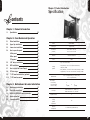
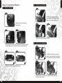
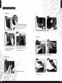
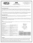
VD5000BNA
User's Manual
Benutzerhandbuch
Mode d’emploi
Manual del usuario
Manuale dell’utente
安裝說明書
用戶手冊
ユーザーズマニュアル
Руководство пользователя
C 2007 Thermaltake Technology Co., Ltd. All Rights Reserved. 2007.06
All other registered trademarks belong to their respective companies. www.thermaltake.com
Tested To Comply
With FCC Standards
FOR HOME OR OFFICE USE
English
English
TM
VD5000BNA
User's Manual
English
English
Chapter 1. Product Introduction
Specification
ontents
Chapter 1. Product Introduction
1-1
Specification
02
Chapter 2. Case Mechanical Operation
2-1
Wheel installation
03
2-2
Upper flap installation
04
2-3
Lower visor installation
04
Case Type
Super Tower
How to open the panel
05
Dimension
(H*W*D)
A.Side panel
05
650 x 240 x 770 mm
25.6 x 9.4 x 30.3 inch
B.Rear panel
05
Material
Aluminum Extrusion
C.Top panel
06
Color
Black
2-5
5.25" device installation
07
2-6
HDD installation
08
Cooling
System
2-4
2-7
How to install the Power Supply
09
2-8
PCI slot usage
09
2-9
7" LCD monitor installation (optional)
10
2-10
7" LCD monitor removal
12
Chapter 3. Motherboard & Lends Installation
1
VD5000BNA
Model
- Up to 12 x 120mm fans
- Front (intake) : 120 x 120 x 25mm blue LED fan,
1300rpm, 17dBA
- Rear (Exhaust) : Two 120 x 120 mm fans, 1300rpm, 17dBA
- Top (Exhaust) : Two 120 x 120 mm fans, 1300rpm, 17dBA
Motherboards
Drive Bays
-7" Drive Bay
-5.25" Drive Bay
-3.5" Drive Bay
9.6" x 9.6" (Micro ATX), 12" x 9.6" (ATX),
12" x 13" (Extend ATX)
2
4
3 (HDD)
or
6
3 (HDD)
3-1
Motherboard installation
13
3-2
Case LED connections
14
Front I/O
e-SATA connector x 1, USB2.0 x 2,
IEEE 1394 Firewire x 1, HD Audio
3-3
USB2.0 & IEEE1394 Firewire connection
15
Expansion Slots
9
3-4
Audio connection
16
3-5
Connexion eSATA
17
Liquid
Cooling
System
Application
N/A
Optional
Components
7" LCD Monitor (P/N:A2413-01)
2
English
English
2-2 Upper flap installation
Chapter 2. Case Mechanical Operation
2-1 Wheel installation
1
1
To attach the upper flap, please
align the visor flap with the hinge
tabs on top of the SwordM case.
These holes are for attaching
case wheels.
2
3
Slide the hinge bar through the visor.
2
3
Please align the 4 holes from the wheel to these four holes on
the case and screw in the wheel with the provided screws.
2-3 Lower visor installation
1
4
To attach the lower visor, please
place the visor over the three holes
on the bottom of the case as shown.
5
Please repeat with the last three wheels.
2
3
Please screw in the visor with supplies hardware through
the three holes circled.
3
4
English
English
2-4 How to open the panel
A.Side panel
1
Remove the two screws,
the upper and lower screws on
the right side, side panel.
2
3
The rear panel should swing open.
C.Top panel
3
2
Holding the left side, side
panel, remove the upper
and lower screws.
1
Caution, the Hydraulic lift will
open automatically once the
screws are removed.
2
1
2
1
2
Pull both sides of latch and turn clockwise.
B.Rear panel
3
1
4
Pull the latch as shown.
Lift top panel.
5
6
English
English
2-5 5.25" device installation
7
2-6 HDD installation
1
2
1
2
3
4
3
4
5
6
5
6
8
English
English
2-7 How to install the Power Supply
2-9 7" LCD monitor installation (Optional)
1
2
1
2
1
Unscrew screws shown
at the top edge of the case
and remove the power
supply cage.
2
Slide the power supply into
the power supply cage.
1
4
3
Place power supply cage
back into position as shown.
Place power supply cage with
power supply as shown and
screw in to secure.
2
3
4
5
2-8 PCI slot usage
2
1
Pull the latch on the
PCI card holder.
Insert the PCI card in the
corresponding slot
2
1
Secure the latch on the
PCI card holder
3
9
10
English
English
2-10 7" LCD monitor removal
6
8
10
11
1
2
3
4
6
7
8
9
7
9
11
12
English
English
Chapter.3 Motherboard & Leads Installation
3-1 Motherboard Installation
3-2 Case LED connections
Each motherboard has different standoff layout. It is highly suggested
that you refer to your motherboard's manual when installing
motherboard into the Case. The cases are applicable with Standard ATX,
Micro ATX motherboards. Your motherboard may require a special I/O
Panel, which should be included with your motherboard.
Placement Direction:
When installing the motherboard, make sure you follow the direction
provided by your motherboard manufacturer. On most standard
motherboards, the edge with external ports goes to the rear part of the
chassis. It is highly recommended that you install CPU, heat sink and
modular components before fixing the motherboard inside the chassis.
On the front of the case, you can find some LEDs and
switch leads (POWER SW*1, POWER LED*1, H.D.D. LED*1,
RESET SW*1, SPEAKER*1).
Please consult user manual of your motherboard manufacturer,
then connect these leads to the panel header on the
motherboard. These leads are usually labeled; if not, please
trace them back to the case front to find out their source.
POWER LED
connects to your M/B at the PLED.
POWER SW
Note
Due to the variety of motherboards on the market, the majority of the
motherboards come with their own I/O plates. It s necessary for you
to remove the fan holder before install the I/O plates.
connects to the PWR connector on the motherboard.
H.D.D LED
connects to the 2-pin labeled HDD LED connector.
RESET SW
connects to the RSW connector on the motherboard.
478
SPEAKER
connector: find out the 4-pin labeled SPEAKER on the
M/B then connect it.
This side towards
the rear of the
chassis
The locations of the
screw holes. Note
these locations and
place included
standoffs on the
chassis first.
Above illustration is a sample of what the motherboard's
layout. For more detail screw hole placement, please refer
to your motherboard manual.
13
14
English
English
3-3 USB2.0 & IEEE1394 Firewire connection
USB connection
Please consult your motherboard manual to find
out the section of "USB connection".
USB2.0
(Brank)
GND1
3-4 Audio connection
Please refer to the following illustration of Audio
connector and your motherboard user manual.
Please select the motherboard which used AC'97 or HD
Audio (Azalia), (be aware of that your audio supports AC'97
or HD Audio (Azalia)) or it will damage your device(s).
On some motherboards, the connectors for Audio are not
the same as the drawing below. Please check with your
motherboard manual before installing.
GND2
Data+1
Data-1
BLACK
AUD GND
PORT1 R BROWN
BLACK
PRESENCE#
PORT2 R YELLOW
ORANGESENSE1_RETURN
PORT1 L
Data+2
Data-2
RED
SENSE_SENDPURPLE
Vcc1
KEY
Vcc 2
PORT2 L
BLUE
GREEN SENSE2_RETURN
AUDIO AZALIA Function
IEEE1394 Firewire connection
Please consult your motherboard manual to find
out the section of "IEEE1394 Firewire connection".
VG
TPB+
VP
TPA-
MIC IN
RED
NC
Front Left Channel
Audio Signal
IEEE1394a
TPA+
Front Microphone
input Signal
Front Microphone MIC POWER BROWN
Power
Front Right Channel
R-OUTYELLOW
Audio Signal
L-OUT
BLUE
BLACK
Front
GROUND
Audio Ground
NC
YELLOW R-RET
Rear Right Channel
Audio Signal
KEY
BLUE
L-RET
Rear Left Channel
Audio Signal
AUDIO AC'97 Function
(Brank)
TPB(Brank)
GND
15
16
English
English
3-5 Connexion eSATA
TM
VD5000BNA
Connect this to your
motherboard at the
HDD LED
arrow
means "+"
Connect this to your
power supply unit.
Connect this to your
motherboard at SATA.
17