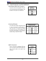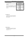
1
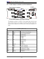
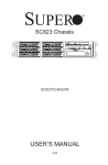
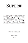
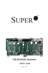
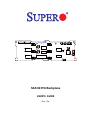
JP13
4TM
JP10
JP34
JP25
S UPER
R
SAS823TQ
JP33
JP50
JP40
M14
JP18
JP36
JP37
REV 1.00A
JP38
JP41
JP43
J8
J5
JP46
JP52
JP45
JP42
H3
J6
U40
JP29
JP51
JP47
J10
JP53
JP44
JP54
H1
J7
J12
JP26
016H
SAS 823TQ Backplane
USER'S GUIDE
Rev. 1.0a
SAS 823TQ Backplane User’s Guide
Table of Contents
Chapter 1: Safety Guidelines
1-1
ESD Safety Guidelines .................................................................................... 1-1
1-2
General Safety Guidelines ............................................................................... 1-1
1-3
An Important Note to Users ............................................................................. 1-1
Chapter 2: Jumper Settings and Pin Definitions
2-1
Front Connectors and Jumpers ....................................................................... 2-1
2-2
Front Connector and Pin Definitions ............................................................... 2-2
2-3
Front Jumper Locations and Pin Definitions ................................................... 2-4
2-4
Rear Connectors and LED Indicators ............................................................ 2-6
User's Guide Revision: Rev. 1.0a
Release Date: 3/16/2007
i
Safety Information and Technical Specifications
Chapter 1
Safety Guidelines
To avoid personal injury and property damage, carefully follow all the safety steps
listed below when accessing your system or handling the components.
1-1
ESD Safety Guidelines
Electric Static Discharge (ESD) can damage electronic components. To prevent damage to your system, it is important to handle it very carefully. The following measures
are generally sufficient to protect your equipment from ESD.
•
Use a grounded wrist strap designed to prevent static discharge.
•
Touch a grounded metal object before removing a component from the antistatic
bag.
•
Handle the RAID card by its edges only; do not touch its components, peripheral
chips, memory modules or gold contacts.
•
When handling chips or modules, avoid touching their pins.
•
Put the card and peripherals back into their antistatic bags when not in use.
1-2
•
General Safety Guidelines
Always disconnect power cables before installing or removing any components
from the computer, including the backplane.
•
Disconnect the power cable before installing or removing any cables from the
backplane.
•
Make sure that the backplane is securely and properly installed on the motherboard to prevent damage to the system due to power shortage.
1-3
•
An Important Note to Users
All images and layouts shown in this user's guide are based upon the latest
PCB Revision available at the time of publishing. The card you have received
may or may not look exactly the same as the graphics shown in this manual.
1-1
SAS 823TQ Backplane User’s Guide
Notes
1-2
Safety Information and Technical Specifications
Chapter 2
Jumper Settings and Pin Definitions
2-1
Front Connectors and Jumpers
1
2
JP13
4TM
JP10
JP34
JP25
S UPER
12
R
SAS823TQ
JP43
J8
J5
JP52
7
JP45
JP42
JP51
JP38
JP41
H3
10
6
U40
JP29
JP47
J10
JP40
M14
9
J6
13
JP50
JP36
JP37
JP46
5
JP33
JP18
REV 1.00A
JP53
JP44
JP54
H1
4
14
8
11
J7
J12
JP26
016H
3
Front Connectors
#1. JP10: 4-Pin PWR Connector
#2. JP13: 4-Pin PWR Connector
#3. JP26: ACT_IN (Activity In LED Header)
#4. JP44: I2C Connector#1
#5. JP45: I2C Connector#2
#6. JP51: SideBand #1
#7. JP52: SideBand #2
#8. MG 9072 Chip
#9. SAS Port #0
#10. SAS Port #1
#11. SAS Port #2
#12. SAS Port #3
#13. SAS Port #4
#14. SAS Port #5
2-1
SAS 823TQ Backplane User’s Guide
2-2
Front Connector and Pin Definitions
#1/#2. Backplane Main Power Connectors
Backplane
Main Power
4-Pin Connector
(JP10 and JP13)
The 4-pin connectors, designated JP10 and
JP13, provide power to the backplane. See
Pin#
the table on the right for pin definitions.
Definition
1
+12V
2 and 3
Ground
4
#3. Activity LED Header
SATA Activity LED Header
Pin Definitions (JP26)
The activity LED header, designated JP26,
is used to indicate the activity status of
+5V
Pin #
Definition
Pin #
Definition
1
ACT IN#0
6
ACT IN#4
2
ACT IN#1
7
ACT IN#5
the Activity LED Header to work properly,
3
ACT IN#2
8
ACT IN#6
connect using a 10-pin LED cable.
4
ACT IN#3
9
ACT IN#7
5
Ground
10
Empty
each SATA drive. The Activity LED Header
is located on the rear of the backplane. For
#4/#5. I2C Connectors
I2C Connector
Pin Definitions (JP44
and JP45)
The I2C Connectors, designated JP44 and
JP45, are used to monitor HDD activity and
Pin#
Definition
status. See the table on the right for pin
1
Data
definitions.
2
Ground
3
Clock
4
No Connection
2-2
Safety Information and Technical Specifications
#6/#7. Sideband Headers
Sideband Headers
(JP51 and JP52)
The sideband headers are designated JP51
Pin #
and JP52.
and JP52. See the table to the right for pin
definitions.
#8. MG9072 Chip
The MG 9072 is an enclosure management
chip that supports the SES-2 controller and
SES-2 protocols.
#9-#14. SAS Ports
The SAS/SATA ports are used to connect
the SAS/SATA drive cables. The 6 ports are
designated #0 - #5.
2-3
Pin #
Definition
2
Backplane
Addressing
(SB5)
1
Controller
ID (SB6)
4
Reset (SB4)
3
GND (SB2)
6
GND (SB3)
5
SDA (SB1)
8
Backplane
ID (SB7)
7
SCL (SB0)
10
No Connection
9
No Connection
For SES-2 to work properly, you must
connect an 8-pin sideband cable to JP51
Definition
SAS 823TQ Backplane User’s Guide
Front Jumper Locations and Pin Definitions
Front Jumper Locations
JP33
JP50
JP34
2-3
JP40
JP13
4TM
JP10
JP34
JP25
S UPER
R
SAS823TQ
JP43
JP18
J5
JP42
JP38
JP36
JP41
JP41
JP46
JP52
JP45
JP42
JP40
M14
JP36
JP37
JP37
J8
JP50
JP18
REV 1.00A
JP43
JP33
JP38
H3
J6
U40
JP29
JP51
JP47
J10
JP29
JP53
JP44
JP54
H1
J7
J12
JP26
016H
I2C and SGPIO Modes and Jumper Settings
This backplane can utilize I2C or SGPIO. I2C is the default mode and can be used
without making changes to your jumpers. The following information details which
jumpers must be configured to use SGPIO mode or restore your backplane to I2C
mode.
I2C Mode (Default)
Jumper
Jumper Setting
Note
JP18
Open
Closed: Buzzer Reset (Default)
JP29
Open
Closed: Chip Reset (Default)
JP33
2-3
Controller ID #1
JP34
1-2
Backplane ID #1
1-2: ID#0
2-3: ID#1
JP36
2-3
Controller ID #2
JP37
2-3
Backplane ID #2
1-2: ID#0
2-3: ID#1
JP38
Closed
I2C Reset #2
JP40
Open
I2C Reset _SDOUT#1
JP41
Open
I2C Reset _SDOUT#2
JP42
2-3
I2C Backplane ID _SDIN#1
JP43
2-3
I2C Backplane ID _SDIN#2
JP50
Closed
I2C Reset #1
2-4
Safety Information and Technical Specifications
SGPIO Mode (Only)
Jumper
Jumper Setting
Note
JP18
Open
Closed: Buzzer Reset (Default)
JP29
Open
Closed: MG9072 Reset (Default)
JP33
1-2
Controller ID #1
JP34
1-2
Backplane ID #1
1-2: ID#0
2-3: ID#1
JP36
1-2
Controller ID #2
JP37
1-2
Backplane ID #2
1-2: ID#0
2-3: ID#1
JP38
Open
I2C Reset #2
JP40
Closed
I2C Reset _SDOUT#1
JP41
Closed
I2C Reset _SDOUT#2
JP42
1-2
I2C Backplane ID _SDIN#1
JP43
1-2
I2C Backplane ID _SDIN#2
JP50
Open
I2C Reset #1
SAS Port Connections in I2C and SGPIO Modes
Remember the following when connecting this backplane:
•
In I2C mode, I2C #1 (JP44) corresponds with SAS ports #0, #1, #2, and #3. I2C
#2 (JP45) corresponds with SAS ports #4 and #5. If you connect the SAS ports
out of order, you will not able to easily identify drives using the LED function.
•
In SGPIO mode, Sideband #1 (JP51) corresponds with SAS ports #0, #1, #2, and
#3. Sideband #2 (JP52) corresponds with SAS ports #4 and #5. If you connect
the SAS ports out of order, you will not able to easily identify drives using the
LED function.
2-5
SAS 823TQ Backplane User’s Guide
2-4
Rear Connectors and LED Indicators
Rear Connector Locations
D15
D8
D12
D5
J4
J1
D18
D19
D13
D6
J2
J9
D21
D20
D14
D7
J11
J3
Rear Connector/LED Indicator Descriptions
823TQ Rear SAS Connectors
Connector
SAS Drive Number
J1
SAS#0 HDD (Connected to HDD)
J2
SAS#1 HDD (Connected to HDD)
J3
SAS#2 HDD (Connected to HDD)
J4
SAS#3 HDD (Connected to HDD)
J9
SAS#4 HDD (Connected to HDD)
J11
SAS#5 HDD (Connected to HDD)
823TQ Rear LED Indicators
Connector
Hard Drive Activity and Failure LEDs
D12
SAS#0 Activity LED (Connected to HDD)
D13
SAS#1 Activity LED (Connected to HDD)
D14
SAS#2 Activity LED (Connected to HDD)
D15
SAS#3 Activity LED (Connected to HDD)
D18
SAS#4 Activity LED (Connected to HDD)
D21
SAS#5 Activity LED (Connected to HDD)
D5
SAS#0 Failure LED (Connected to HDD)
D6
SAS#1 Failure LED (Connected to HDD)
D7
SAS#2 Failure LED (Connected to HDD)
D8
SAS#3 Failure LED (Connected to HDD)
D19
SAS#4 Failure LED (Connected to HDD)
D20
SAS#5 Failure LED (Connected to HDD)
2-6